EP0508541A2 - Procédé pour la fabrication d'une pièce métallique en forme d'anneau ou arqué - Google Patents
Procédé pour la fabrication d'une pièce métallique en forme d'anneau ou arqué Download PDFInfo
- Publication number
- EP0508541A2 EP0508541A2 EP92200987A EP92200987A EP0508541A2 EP 0508541 A2 EP0508541 A2 EP 0508541A2 EP 92200987 A EP92200987 A EP 92200987A EP 92200987 A EP92200987 A EP 92200987A EP 0508541 A2 EP0508541 A2 EP 0508541A2
- Authority
- EP
- European Patent Office
- Prior art keywords
- sheet metal
- rollers
- metal ring
- sheet
- roller
- Prior art date
- Legal status (The legal status is an assumption and is not a legal conclusion. Google has not performed a legal analysis and makes no representation as to the accuracy of the status listed.)
- Withdrawn
Links
Images

Classifications
-
- B—PERFORMING OPERATIONS; TRANSPORTING
- B21—MECHANICAL METAL-WORKING WITHOUT ESSENTIALLY REMOVING MATERIAL; PUNCHING METAL
- B21D—WORKING OR PROCESSING OF SHEET METAL OR METAL TUBES, RODS OR PROFILES WITHOUT ESSENTIALLY REMOVING MATERIAL; PUNCHING METAL
- B21D53/00—Making other particular articles
- B21D53/16—Making other particular articles rings, e.g. barrel hoops
- B21D53/18—Making other particular articles rings, e.g. barrel hoops of hollow or C-shaped cross-section, e.g. for curtains, for eyelets
Definitions
- the invention relates to a method for producing an annular or arcuate metal part.
- Metal parts of this type are used, for example, in a so-called C-arm of an X-ray examination device, where they serve to guide or hold an X-ray emitter and an X-ray image receiver aligned thereon. It is known to produce such C-arms from cast aluminum. Despite the use of aluminum, such arches have a considerable weight if they have a large diameter (e.g. 1.50 m or more) and at the same time are supposed to be stable.
- the object of the present invention is therefore to provide a method for producing a ring-shaped or arc-shaped metal part which has a high stability and a low weight even with large diameters.
- This object is achieved in that a sheet is bent into a ring and the ends of the sheet are connected to each other that circumferential elevations or depressions are formed in the sheet metal ring thus formed by means of rollers arranged inside and outside the sheet, the cooperating profiles of which generating elevations or depressions are adapted, and that during the embossing process, the rollers are moved simultaneously in the radial direction and parallel to the axis of the sheet metal ring, so that the sheet metal ring is only stretched or compressed in the radial direction.
- the metal part is made of sheet metal formed, which is bent into a sheet metal ring, in which elevations or depressions are produced which run around the circumference of the sheet metal ring in order to achieve the required stability.
- elevations or depressions are produced by means of rollers, the shape of which is adapted to the shape of the elevations and depressions to be produced and which are moved during the stamping process both parallel to the axis and perpendicularly thereto, ie in the radial direction of the sheet metal ring.
- roller position at the beginning of the embossing process and the speed of these two movements are coordinated so that the sheet metal ring is only stretched or compressed in the radial direction, so that each surface line of the sheet metal ring (in a plane containing the axis of symmetry) maintains its length. This results in high stability.
- the sheet is also stretched or compressed - depending on whether an increase or a depression is pressed into the sheet metal ring - but this is only caused by the changes in the radial dimensions caused during the stamping process.
- There is no stretching or compression in the axial direction because the sheet metal strip is only “bent” by means of the rollers, so that the surface line of the sheet metal ring is not extended during the stamping process.
- a preferred embodiment of the invention provides for the use of a metal part produced according to one of claims 1 to 5 in an x-ray device for guiding or holding an x-ray emitter and an x-ray image receiver aligned thereon.
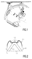
- Fig. 1 denotes a C-arm, which carries at its ends an X-ray emitter 2 and an X-ray image intensifier 3, which amplifies the image generated by the X-ray emitter 2 into a visible image Brightness.
- This visible image is converted into an electrical signal in the usual way by means of a television camera, so that electrically controllable image reproduction is possible.
- the C-arm 1 is displaceably arranged in a holder 4, so that it describes a path within this guide, the center of curvature or axis of symmetry being designated by 5.
- the central beam 6 intersects (this is the beam that connects the focus of the X-ray emitter to the center of the image intensifier 3) and the axis 7 about which the holder 4 is rotatably mounted.
- This storage is in turn guided on a further C-arm 8, which is mounted in a ceiling carriage 9 around the point 5.
- the cross section is symmetrical to a plane perpendicular to the axis of symmetry, but the symmetrical design is not a prerequisite for the invention.
- the cross section comprises a profile 100 located on the outside of the C-arm, which is connected on its two side surfaces to a guide rail 101 each shown in dashed lines, which are guided between rollers (not shown) in the holders 4 and 9 (FIG. 1) .
- the inside of the cross section is closed with a sheet 102 which is curved in a circle around the center of curvature of the arc.
- Stabilizing plates 103 are arranged on the circumference of the arch at regular intervals, which prevent deformation of the cross section or twisting of the C-arm.
- the invention is concerned with the production of the profiled metal part 100.
- a strip of sheet metal is bent into a ring and the ends of the sheet are connected to one another, for example, by welding.
- Aluminum sheet is preferably used because of its low weight.
- the sheet metal strip can have a thickness of 2 mm, a width of 500 mm and a length of approximately 5,700 mm, for example.
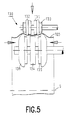
- each roller station 120, 130 and 140 contains rotating rollers which rotate the sheet metal ring 5 around its center and which produce the elevations or depressions in that the outer or the inner rollers during the stamping process in a radial direction (towards the axis of symmetry 5 towards or away from it) or be moved in parallel.
- the three rolls are distributed over an arc of the sheet metal ring, which is smaller than 180 o , so that after the stamping process and the removal of the outer rolls, the profiled sheet metal ring can be easily removed.
- the shafts that drive the rollers must be arranged on an arc that is determined by the diameter of the profiled ring.
- roller stations More than three roller stations can be provided. In this case too, the arc over which these roller stations are distributed must be shorter than a semicircle.
- FIGS. 4 to 7 is rotated in a o in comparison to figure 3 through 90 and more or less greatly enlarged view illustrating the deformation of the sheet metal ring in different stages.
- FIGS. 4 to 6 show a roller station at the beginning, during and at the end of an embossing process, while FIG. 7 explains the final bending of the sheet metal edges.
- the roller station 130 (like the other two roller stations) contains two identical rollers arranged outside the sheet metal ring and symmetrical to a central plane of the sheet metal ring 100.
- the rollers can be driven via a shaft 137 and can be adjusted in opposite directions to one another in the axial direction.
- the shaft 137 can be moved toward or away from the axis of symmetry 5 (FIG. 1).
- Each roller comprises a disc-shaped inner, middle, and outer part 131..133.
- the roller parts have different thicknesses and different diameters; the outermost roller part 133 has the smallest and the middle roller part 132 the largest diameter.
- the part of the roller station 130 located below the sheet metal ring comprises three rollers, namely a centrally arranged roller 134, and two identical rollers arranged in mirror symmetry therewith, which have a disk-shaped inner part 135 and a cup-shaped part 136 which is curved outwards.
- the roller part 135 has a slightly smaller diameter than the central roller 134 and a significantly smaller diameter than the roller part 136.
- the three inner rollers are driven by a shaft 138 which runs parallel to the shaft 137 and parallel to the axis of symmetry 5 of the sheet metal ring 100 (the As a rule, the sheet metal ring does not yet have the desired circular shape at the start of the stamping process, but this arises automatically during the stamping process). While the central roller 134 is firmly connected to the shaft 138, the outer rollers (135, 136) can be moved in opposite directions to one another in the axial direction.
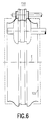
- the cross sections of the rollers are chosen so that - when the inner and outer rollers are pushed together - complementary contours are created, as is special Fig. 6 clearly shows. These contours therefore determine the profile of the sheet 100 after the stamping process.
- the width of the central roller 134 corresponds to the sum of the width of the two inner parts 131 minus two sheet thicknesses
- the width of the middle disk 132 of the upper roller must correspond to the width of the inner disk 135 of the lower roller (minus twice the sheet thickness).
- the difference in the diameters of the middle disc 132 and the inner disc 131 of the upper roller must correspond to the difference between the diameters of the central roller 134 on the one hand and the inner disc 135 on the other.
- the drive of the roller stations is switched on, so that the sheet metal ring is set in rotation between the upper and lower roller pairs.
- Lateral guides can be provided which hold the sheet metal ring in a defined plane. These guides are superfluous for advanced embossing processes because the sheet metal ring is then guided through the rollers. the embossing process is carried out in two phases.
- the flanks 105 (see FIG. 2) of the profile begin to be shaped.
- the lower rollers are pushed together in the axial direction, while the upper rollers are moved radially downward, but not in the axial direction.
- the speeds of displacement of the upper roller in the radial direction and the lower rollers in the axial direction are coordinated with one another in such a way that the upper and lower rollers describe an arc on the right and on the left relative to one another.
- the sheet metal ring is bent inwards around the inner edge of the outer roller part 136 without the rollers moving in the axial direction relative to the sheet metal ring. Therefore, the length of the surface line of the sheet metal ring does not change (in a plane containing the axis of symmetry).
- Fig. 5 shows the rollers during the stamping process during this first phase. It can be seen that the sheet metal ring has deformed in the vicinity of the outer part 136 of the lower roller, while it has not yet been deformed in the region between the middle roller parts 132 of the upper roller.
- the second phase of the stamping process begins when the sheet metal ring touches the central roller 134. Then they have to upper rollers on mirror-symmetrical arcuate tracks are moved down to the central roller 134 without the sheet metal ring being displaced in the axial direction with respect to any of the rollers. For this arcuate movement, the upper rollers must be moved radially in addition to the downward movement. At the same time, the outer rollers (135, 136) located below the sheet metal ring are moved together until they touch the central roller.
- Fig. 6 shows the arrangement after this second phase of the stamping process.
- the sheet metal ring is indicated before the embossing process begins. It can be seen that the width of the ring has decreased, while the diameter is enlarged in some places, which results in stretching, and is reduced in other places, so that there is compression. The length of the surface line of the sheet metal ring, however, is unchanged.
- the sheet metal ring can be profiled in different ways if the roll shape, the position of the rolls at the start of the embossing process and the speed during the axial and radial displacement of the rolls are adjusted accordingly .
- the central elevation 106 FIG. 2
- the central roller 134 would have to have a larger diameter and the distance between the upper rollers and the outer rollers (bottom) from one another would have to be increased accordingly.
- the central roller 134 could be omitted, while only a single roller would be required above the sheet metal ring with a wide central roller part (with the diameter of the part 132) and two outer ones Roller parts 133, as shown in Fig. 4.
- the second phase of the stamping process would also be omitted.
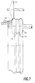
- Fig. 7 the final operation is shown.
- the upper rollers have been removed upward from the sheet metal ring 100, and instead the outer part of the sheet metal ring is adapted to the shape of the outer part 136 by one of the two lower rollers with a further roller 161.
- a fold holder 162 ensures that there are no folds in the sheet during this deformation process. The outermost edges of the sheet metal ring cannot be deformed in this way. You will therefore be cut off.
Landscapes
- Engineering & Computer Science (AREA)
- Mechanical Engineering (AREA)
- Shaping Metal By Deep-Drawing, Or The Like (AREA)
- Bending Of Plates, Rods, And Pipes (AREA)
- Forging (AREA)
Applications Claiming Priority (2)
| Application Number | Priority Date | Filing Date | Title |
|---|---|---|---|
| DE19914111780 DE4111780A1 (de) | 1991-04-11 | 1991-04-11 | Verfahren zum herstellen eines ring- oder bogenfoermigen metallteils |
| DE4111780 | 1991-04-11 |
Publications (2)
| Publication Number | Publication Date |
|---|---|
| EP0508541A2 true EP0508541A2 (fr) | 1992-10-14 |
| EP0508541A3 EP0508541A3 (fr) | 1992-11-04 |
Family
ID=6429329
Family Applications (1)
| Application Number | Title | Priority Date | Filing Date |
|---|---|---|---|
| EP19920200987 Withdrawn EP0508541A3 (fr) | 1991-04-11 | 1992-04-07 | Procédé pour la fabrication d'une pièce métallique en forme d'anneau ou arqué |
Country Status (3)
| Country | Link |
|---|---|
| EP (1) | EP0508541A3 (fr) |
| JP (1) | JPH05131221A (fr) |
| DE (1) | DE4111780A1 (fr) |
Cited By (5)
| Publication number | Priority date | Publication date | Assignee | Title |
|---|---|---|---|---|
| DE19536053A1 (de) * | 1995-09-28 | 1997-04-10 | Schaeffler Waelzlager Kg | Rollierverfahren zur Herstellung eines Endanschlages an einer Schaltarretierung |
| EP1514702A1 (fr) * | 2003-09-10 | 2005-03-16 | Continental Aktiengesellschaft | Roue de véhicule comportant un corps d'appui pour roulage à plat |
| WO2009008780A1 (fr) * | 2007-07-09 | 2009-01-15 | Volvo Aero Corporation | Procédé de production d'une structure de paroi annulaire |
| CN106001199A (zh) * | 2016-06-29 | 2016-10-12 | 安徽汇展热交换系统股份有限公司 | 一种散热器导风罩圆弧围板压弯装置 |
| EP4401898A4 (fr) * | 2021-09-17 | 2025-11-26 | Asc Eng Solutions Llc | Machine à rainer les tuyaux |
Families Citing this family (4)
| Publication number | Priority date | Publication date | Assignee | Title |
|---|---|---|---|---|
| DE4214087C1 (en) * | 1992-04-29 | 1993-05-27 | Siemens Ag, 8000 Muenchen, De | System for holding X=ray transmitter and receiver - has two C=shaped curved arms, one for carrying the transmitter and receiver and the other for carrying the first arm |
| DE4319598C2 (de) * | 1993-06-14 | 1996-02-22 | Siemens Ag | Medizinisches Gerät mit einem C-Bogen und einer Kabelführung |
| DE102012212717A1 (de) * | 2012-07-19 | 2014-01-23 | Otto Bihler Handels-Beteiligungs-Gmbh | Rollbiegeverfahren und -vorrichtung |
| DE102017208530A1 (de) * | 2017-05-19 | 2018-11-22 | Siemens Healthcare Gmbh | Medizinische Untersuchungs- oder Behandlungseinrichtung, umfassend einen C-Bogen |
Family Cites Families (4)
| Publication number | Priority date | Publication date | Assignee | Title |
|---|---|---|---|---|
| DE537837C (de) * | 1930-09-16 | 1931-11-07 | Schuler L Ag | Verfahren zum Herstellen von Sicken oder Rillen in Fassruempfen o. dgl. |
| US3357229A (en) * | 1965-02-09 | 1967-12-12 | Grotnes Machine Works Inc | Apparatus for forming a beaded shell |
| DE1299269B (de) * | 1965-09-03 | 1969-07-17 | Kronprinz Ag | Felgenprofiliermaschine zur Herstellung von zylindrischen Blech-profilen aus Blechringen, insbesondere von Tiefbettfelgen |
| DE2204953A1 (de) * | 1972-02-03 | 1973-08-09 | Leifeld & Co | Verfahren und vorrichtung zur herstellung von steilschulterfelgen |
-
1991
- 1991-04-11 DE DE19914111780 patent/DE4111780A1/de not_active Withdrawn
-
1992
- 1992-04-07 EP EP19920200987 patent/EP0508541A3/fr not_active Withdrawn
- 1992-04-09 JP JP8889792A patent/JPH05131221A/ja active Pending
Cited By (7)
| Publication number | Priority date | Publication date | Assignee | Title |
|---|---|---|---|---|
| DE19536053A1 (de) * | 1995-09-28 | 1997-04-10 | Schaeffler Waelzlager Kg | Rollierverfahren zur Herstellung eines Endanschlages an einer Schaltarretierung |
| DE19536053C2 (de) * | 1995-09-28 | 2001-05-31 | Schaeffler Waelzlager Ohg | Unter Anwendung eines Spanlosverfahrens hergestellter Endanschlag an einer Schaltarretierung |
| EP1514702A1 (fr) * | 2003-09-10 | 2005-03-16 | Continental Aktiengesellschaft | Roue de véhicule comportant un corps d'appui pour roulage à plat |
| WO2009008780A1 (fr) * | 2007-07-09 | 2009-01-15 | Volvo Aero Corporation | Procédé de production d'une structure de paroi annulaire |
| CN106001199A (zh) * | 2016-06-29 | 2016-10-12 | 安徽汇展热交换系统股份有限公司 | 一种散热器导风罩圆弧围板压弯装置 |
| EP4401898A4 (fr) * | 2021-09-17 | 2025-11-26 | Asc Eng Solutions Llc | Machine à rainer les tuyaux |
| US12533721B2 (en) | 2021-09-17 | 2026-01-27 | ASC Engineered Solutions, LLC | Pipe groover |
Also Published As
| Publication number | Publication date |
|---|---|
| EP0508541A3 (fr) | 1992-11-04 |
| DE4111780A1 (de) | 1992-10-15 |
| JPH05131221A (ja) | 1993-05-28 |
Similar Documents
| Publication | Publication Date | Title |
|---|---|---|
| EP0290874B1 (fr) | Machine pour border et rétrécir les boîtes cylindriques aux deux extrémités | |
| EP2024111B1 (fr) | Dispositif et procédé pour produire des corps profilés | |
| DE69710610T2 (de) | Vorrichtung zum rollformen von blechformpfetten oder ähnlichem aus metallplatten | |
| EP0508541A2 (fr) | Procédé pour la fabrication d'une pièce métallique en forme d'anneau ou arqué | |
| DE69009993T2 (de) | Vorrichtung zum bilden eines rohres aus blattmetallplatte. | |
| DE69500280T2 (de) | Verfahren und Vorrichtung zur Herstellung eines Rands, insbesondere an einem Lampenreflektor | |
| DE102008000219A1 (de) | Kaltwalzverfahren zur Herstellung eines Profils | |
| WO2019238430A1 (fr) | Machine de laminage à froid et procédé de génération d'un profil au niveau d'une pièce | |
| DE19723073C2 (de) | Verfahren zur Herstellung eines rotationssymmetrischen Werkstücks | |
| DE19708027A1 (de) | Verfahren zum Herstellen einer metallischen Zahnradscheibe | |
| EP2576095B1 (fr) | Dispositif pour déformer un élément d'un semi-produit notamment plan | |
| EP3515617B1 (fr) | Outil et machine-outil ainsi que procédé d'usinage de pièces en forme de plaque | |
| DE2641573A1 (de) | Druckpresse zum biegen des randstreifens eines ebenen bleches | |
| EP2165785B1 (fr) | Dispositif et procédé de fabrication de rainures longitudinales dans des pièces usinées cylindriques | |
| EP0555631B1 (fr) | Procédé de fabrication d'élément de transmission à denture externe | |
| DE4226402A1 (de) | Verfahren zur Herstellung von langen dickwandigen Rohren durch Biegen aus einer Metallplatte und Vorrichtung zur Ausführung des Verfahrens | |
| DE102012014987A1 (de) | Hochschlagvorrichtung für Reifenseitenwände | |
| EP0429815B1 (fr) | Dispositif pour formage d'une bride ou similaire, en particulier à la fin d'un tube métallique à paroi mince | |
| DE9103358U1 (de) | Anordnung zum Umformen einer Ronde aus Metall durch Drücken | |
| DE19718629A1 (de) | Verfahren zum Walzen von Kegelrädern auf einer Axial-Gesenkwalzmaschine und Werkzeuganordnung zu dessen Durchführung | |
| DE102014115426A1 (de) | Vorrichtung und Verfahren zum kontinuierlichen voranschreitenden Umformen von Metallbändern zu einem Profil mit längsveränderlichem Querschnitt | |
| DE19525868A1 (de) | Verfahren zum Herstellen von ringförmigen Werkstücken aus Metall mit profiliertem Querschnitt und Walzwerk zu dessen Durchführung | |
| DE2825234A1 (de) | Verfahren und vorrichtung zum formwalzen bzw. drueckformen insbesondere einer abschlusswand | |
| DE3419182A1 (de) | Verfahren und vorrichtung zum festlegen eines einfassungsbleches an einer durchgangsoeffnung einer flachdichtung | |
| DE3741596C2 (fr) |
Legal Events
| Date | Code | Title | Description |
|---|---|---|---|
| PUAI | Public reference made under article 153(3) epc to a published international application that has entered the european phase |
Free format text: ORIGINAL CODE: 0009012 |
|
| PUAL | Search report despatched |
Free format text: ORIGINAL CODE: 0009013 |
|
| AK | Designated contracting states |
Kind code of ref document: A2 Designated state(s): DE FR GB IT |
|
| AK | Designated contracting states |
Kind code of ref document: A3 Designated state(s): DE FR GB IT |
|
| STAA | Information on the status of an ep patent application or granted ep patent |
Free format text: STATUS: THE APPLICATION IS DEEMED TO BE WITHDRAWN |
|
| 18D | Application deemed to be withdrawn |
Effective date: 19930505 |