EP0508335B1 - Vorrichtung zum Abscheiden von Leichtstoffen aus Sand und Kies - Google Patents
Vorrichtung zum Abscheiden von Leichtstoffen aus Sand und Kies Download PDFInfo
- Publication number
- EP0508335B1 EP0508335B1 EP92105859A EP92105859A EP0508335B1 EP 0508335 B1 EP0508335 B1 EP 0508335B1 EP 92105859 A EP92105859 A EP 92105859A EP 92105859 A EP92105859 A EP 92105859A EP 0508335 B1 EP0508335 B1 EP 0508335B1
- Authority
- EP
- European Patent Office
- Prior art keywords
- inner chamber
- overflow
- outer chamber
- chamber
- raw material
- Prior art date
- Legal status (The legal status is an assumption and is not a legal conclusion. Google has not performed a legal analysis and makes no representation as to the accuracy of the status listed.)
- Expired - Lifetime
Links
- 239000004576 sand Substances 0.000 title claims abstract description 19
- 239000000463 material Substances 0.000 title claims abstract description 16
- 239000002994 raw material Substances 0.000 claims abstract description 30
- 238000000034 method Methods 0.000 claims abstract description 7
- 229910052500 inorganic mineral Inorganic materials 0.000 claims abstract description 3
- 239000011707 mineral Substances 0.000 claims abstract description 3
- 238000000926 separation method Methods 0.000 claims description 9
- XLYOFNOQVPJJNP-UHFFFAOYSA-N water Substances O XLYOFNOQVPJJNP-UHFFFAOYSA-N 0.000 claims description 6
- 239000002245 particle Substances 0.000 claims 1
- 238000000605 extraction Methods 0.000 description 5
- 239000012535 impurity Substances 0.000 description 4
- 230000008719 thickening Effects 0.000 description 4
- 238000013461 design Methods 0.000 description 3
- 238000004062 sedimentation Methods 0.000 description 3
- 238000004140 cleaning Methods 0.000 description 2
- 239000000356 contaminant Substances 0.000 description 2
- 239000012530 fluid Substances 0.000 description 2
- 239000000203 mixture Substances 0.000 description 2
- 230000001105 regulatory effect Effects 0.000 description 2
- 239000007787 solid Substances 0.000 description 2
- 239000002023 wood Substances 0.000 description 2
- 230000006978 adaptation Effects 0.000 description 1
- 230000015572 biosynthetic process Effects 0.000 description 1
- 238000011109 contamination Methods 0.000 description 1
- 230000001276 controlling effect Effects 0.000 description 1
- 238000011161 development Methods 0.000 description 1
- 230000018109 developmental process Effects 0.000 description 1
- 238000005192 partition Methods 0.000 description 1
- 238000012216 screening Methods 0.000 description 1
- 239000002689 soil Substances 0.000 description 1
- 239000000126 substance Substances 0.000 description 1
- 238000012549 training Methods 0.000 description 1
- 238000011144 upstream manufacturing Methods 0.000 description 1
Images

Classifications
-
- B—PERFORMING OPERATIONS; TRANSPORTING
- B03—SEPARATION OF SOLID MATERIALS USING LIQUIDS OR USING PNEUMATIC TABLES OR JIGS; MAGNETIC OR ELECTROSTATIC SEPARATION OF SOLID MATERIALS FROM SOLID MATERIALS OR FLUIDS; SEPARATION BY HIGH-VOLTAGE ELECTRIC FIELDS
- B03B—SEPARATING SOLID MATERIALS USING LIQUIDS OR USING PNEUMATIC TABLES OR JIGS
- B03B5/00—Washing granular, powdered or lumpy materials; Wet separating
- B03B5/62—Washing granular, powdered or lumpy materials; Wet separating by hydraulic classifiers, e.g. of launder, tank, spiral or helical chute concentrator type
-
- B—PERFORMING OPERATIONS; TRANSPORTING
- B03—SEPARATION OF SOLID MATERIALS USING LIQUIDS OR USING PNEUMATIC TABLES OR JIGS; MAGNETIC OR ELECTROSTATIC SEPARATION OF SOLID MATERIALS FROM SOLID MATERIALS OR FLUIDS; SEPARATION BY HIGH-VOLTAGE ELECTRIC FIELDS
- B03B—SEPARATING SOLID MATERIALS USING LIQUIDS OR USING PNEUMATIC TABLES OR JIGS
- B03B11/00—Feed or discharge devices integral with washing or wet-separating equipment
-
- B—PERFORMING OPERATIONS; TRANSPORTING
- B03—SEPARATION OF SOLID MATERIALS USING LIQUIDS OR USING PNEUMATIC TABLES OR JIGS; MAGNETIC OR ELECTROSTATIC SEPARATION OF SOLID MATERIALS FROM SOLID MATERIALS OR FLUIDS; SEPARATION BY HIGH-VOLTAGE ELECTRIC FIELDS
- B03B—SEPARATING SOLID MATERIALS USING LIQUIDS OR USING PNEUMATIC TABLES OR JIGS
- B03B5/00—Washing granular, powdered or lumpy materials; Wet separating
Definitions
- the invention relates to a device for separating Light materials from mineral raw materials, especially from Sand and gravel, with a fluidized bed method working sorting area, with a job for that Raw material, a discharge for the cleaned material and an overflow for the light materials.
- a generic device results from the company publication "LINATEX - LINARD", 04.83 from the Schauenburg company Maschinen- und Anlagenbau GmbH as from the execution 2 of patent specification DE-A-34 18 492.
- the known device consists of a cylindrical single chamber container with an almost flat bottom and one in it arranged discharge for the cleaned sand.
- Above the Soil is a jet floor through which underwater flows arranged, above which during operation of the device the so-called fluidized bed space builds up, in which under Utilization of the fines contained in the raw material feed the sand has a very high turbidity density, which organic impurities contained in the raw material feed, especially heavily carbonized wood leaves so that the contamination with the overflow water be washed out.
- the known device has the disadvantage that that the raw material feed is very solid have to be; this is the case with the extraction of dry matter to be cleaned Raw material a task directly via a belt conveyor and in the case of wet extraction in the form of a sand / water mixture a pre-thickening of the raw material feed, for example required in hydrocyclones.
- the wet extraction is predominant, the known device requires the upstream connection of a additional thickening level with a corresponding one mechanical and in terms of controlling the composition of tasks procedural effort.
- the invention is therefore based on the object Generic device to improve such that no restrictions, especially when it comes to the raw material feed regarding the sands and gravel to be cleaned exist and that the cleaning or separation success is further improved.
- the basic idea of the invention is that the Two-stage device with an inner chamber with a assigned task arrangement for the raw material task and the separation of the coarse sand and the inner chamber ring-like surrounding and separated by an overflow External chamber for sorting fine sand is formed, the outer chamber being according to the fluidized bed process working sorting area is formed followed by the overflow for the light materials.
- the device allows a high throughput because the sorting stage is significantly relieved.
- there are no special requirements to set the solids content in the raw material task are; it can dilute the raw material in almost any be abandoned because in the inner chamber next to the partition the coarse sands also an equalization of the overflow into the outer chamber with the sorting area takes place or can be set.
- an outer annular gap centrally free impact body arranged, with a feed tube ends at a distance above the impact body.
- the surface of the impact body sloping towards the annular gap be formed, which may alternatively be useful the surface of the impact body with a general tendency to To form an annular gap wave-shaped, whereby a certain Sedimentation of the raw material feed before entering the Annular gap occurs.
- Feed tube on with a feed line for the raw material connected feed pipe arranged; still the task tube arranged longitudinally so that the distance between the exit of the raw material from the feed pipe and can adjust the impact on the impact body.
- the dimensions of the inner chamber or associated impact body and the setting of the flow velocity in the annular gap are such pretend that the grain size of the in the inner chamber separation between coarse and fine sands is between 2 mm and 0.5 mm.
- the invention thus deviates from a simple overflow control in the form of an edge trained overflow and looks at mutual Distance from inner chamber to outer chamber one as inclined Area trained overflow. That is the advantage connected that in turn an equalization on the overflow surface overflow of fine sands with those in them impurities still contained; at the same time certain sedimentation and pre-thickening of the Material overflow because the overflow water faster drains away. So the sorting success is that of the outer chamber assigned sorting area further improved.
- the nozzle bottom with a controllable Fine sand discharge is provided. It can be done after a Embodiment of the invention may be provided
- the height of the nozzle base is infinitely adjustable.
- the area ratio is preferably between 1: 3.5 to 1: 5.5.
- the device consists of a cylindrical inner chamber 10 with a feed arrangement 11.
- the inner chamber 10 has at its lower end a conical taper Trigger area 12 with a controllable trigger 13 which can be actuated via a mechanism 14.
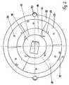
- a mechanism 14 Like Figure 2 better can be seen are on the outer circumference of the inner chamber 10 Lines 22 are arranged for the supply of underwater.
- the task arrangement 11 consists of a centrically above the Inner chamber 10 arranged feed tube 15, which is longitudinally displaceable is set up. Inside the feed tube 15 is a feed pipe 16 which is arranged on its upper end with a feed line 17 for the raw material feed connected is; in addition, a vent 18 in the Task arrangement 11 formed.
- baffle 19 arranged at a General inclination outwards a wavy surface having. Between the outer wall 20 of the inner chamber 10 and the impact body 19 remains an annular gap 21.
- the inner chamber 10 with a ring surrounding it at a distance is one
- the outer chamber 23 is arranged, the inner wall 24 of which Surrounds outer wall 20 of the inner chamber 10 at a distance. This distance between the inner chamber 10 and outer chamber 23 is bridged by an overflow 25, which as to the outer chamber 23 is inclined surface 26 is formed.
- the Outer chamber 23 has a nozzle base 27 arranged accordingly the representation in Figure 2 from six individual Segments 28 exists. Each individual segment 28 of the nozzle base 27 has a mechanism 29 or associated electronics controlled discharge member 30.
- the outer chamber 23 with an inlet 31 for the provide the required underwater.
- At the top of the Outer chamber 23 includes an overflow 32 with trigger 33 for the Overflow water and the washed out light substances.
- the operation of the device according to the invention takes place Supply of the raw material feed via the feed line 17 and that supply pipe 16 arranged in the feed pipe 15; due to the longitudinal displaceability of the feed tube 15 can Distance between the exit of the raw material and the Baffle 19 are adjusted so that at this point a corresponding equalization of the task flow in Adaptation to the subsequent grain size separation possible is.
- the material hits the impact body 19 and distributed over this until it gets into the annular gap 21 where depending on the flow rate set there a grain size separation of the raw material feed a grain size between 2 mm and about 0.5 mm.
- the coarse sands with a grain size of more than 0.5 mm sink into the discharge area 12 of the inner chamber 10 and are discharged in a regulated manner via the trigger 13.
Landscapes
- Separation Of Solids By Using Liquids Or Pneumatic Power (AREA)
- Physical Or Chemical Processes And Apparatus (AREA)
- Combined Means For Separation Of Solids (AREA)
Applications Claiming Priority (2)
| Application Number | Priority Date | Filing Date | Title |
|---|---|---|---|
| DE4111376 | 1991-04-09 | ||
| DE4111376 | 1991-04-09 |
Publications (3)
| Publication Number | Publication Date |
|---|---|
| EP0508335A2 EP0508335A2 (de) | 1992-10-14 |
| EP0508335A3 EP0508335A3 (en) | 1994-10-12 |
| EP0508335B1 true EP0508335B1 (de) | 1998-07-08 |
Family
ID=6429090
Family Applications (1)
| Application Number | Title | Priority Date | Filing Date |
|---|---|---|---|
| EP92105859A Expired - Lifetime EP0508335B1 (de) | 1991-04-09 | 1992-04-04 | Vorrichtung zum Abscheiden von Leichtstoffen aus Sand und Kies |
Country Status (4)
| Country | Link |
|---|---|
| EP (1) | EP0508335B1 (enExample) |
| AT (1) | ATE168043T1 (enExample) |
| DE (1) | DE59209400D1 (enExample) |
| PL (1) | PL167497B1 (enExample) |
Families Citing this family (6)
| Publication number | Priority date | Publication date | Assignee | Title |
|---|---|---|---|---|
| DE19540644C1 (de) * | 1995-11-02 | 1997-04-03 | Allmineral Aufbereitungstech | Vorrichtung zum Abscheiden von Leichtstoffen aus mineralischen Rohstoffen |
| DE19630085C2 (de) * | 1996-07-26 | 2001-03-08 | Allmineral Aufbereitungstech | Verfahren zur Steuerung einer Sortier- und Klassiervorrichtung für Sand und Kies |
| RU2166994C2 (ru) * | 1997-02-04 | 2001-05-20 | Воробьев Леонид Юрьевич | Устройство для очистки и обогащения песков |
| RU2190477C1 (ru) * | 2001-09-18 | 2002-10-10 | Бабичев Николай Игоревич | Устройство для очистки частиц минерального сырья от поверхностных примесей |
| DE102009033476A1 (de) | 2009-07-17 | 2011-01-27 | Lösel, Kai | Verfahren zur Gewinnung von Schwergutfeinpartikeln aus einem Sandaustrag einer Nassklassiereinrichtung und Vorrichtung dazu |
| CN101850293B (zh) * | 2010-04-23 | 2013-02-13 | 中国矿业大学 | 脱泥型液固流化床粗煤泥分选分级装置 |
Family Cites Families (4)
| Publication number | Priority date | Publication date | Assignee | Title |
|---|---|---|---|---|
| DE3028686C2 (de) * | 1980-07-29 | 1983-07-14 | Buckau-Walther AG, 4048 Grevenbroich | Vorrichtung zum Waschen von Schüttgut |
| DE3418492C2 (de) * | 1984-05-18 | 1986-07-31 | Heiner Dipl.-Ing. 4100 Duisburg Kreyenberg | Vorrichtung zur Behandlung von Gewässerablagerungen |
| DE3427395A1 (de) * | 1984-07-25 | 1986-02-06 | Werner Prof. Dr.-Ing. 2150 Buxtehude Bauer | Verfahren zur abscheidung von verunreinigungen aus problemschlaemmen und vorrichtung zur durchfuehrung dieses verfahrens |
| DE3902665A1 (de) * | 1989-01-30 | 1990-08-02 | Harald Garbe | Verfahren zur veredelung von anorganisch nichtmetallischen fasern insbesondere keramikfasern sowie vorrichtung zur durchfuehrung dieses verfahrens |
-
1992
- 1992-04-04 EP EP92105859A patent/EP0508335B1/de not_active Expired - Lifetime
- 1992-04-04 DE DE59209400T patent/DE59209400D1/de not_active Expired - Lifetime
- 1992-04-04 AT AT92105859T patent/ATE168043T1/de active
- 1992-04-08 PL PL92294147A patent/PL167497B1/pl unknown
Also Published As
| Publication number | Publication date |
|---|---|
| PL294147A1 (enExample) | 1993-02-08 |
| EP0508335A3 (en) | 1994-10-12 |
| DE59209400D1 (de) | 1998-08-13 |
| ATE168043T1 (de) | 1998-07-15 |
| PL167497B1 (pl) | 1995-09-30 |
| EP0508335A2 (de) | 1992-10-14 |
Similar Documents
| Publication | Publication Date | Title |
|---|---|---|
| AT243721B (de) | Vorrichtung zum Sortieren oder Klassieren fester, körniger Stoffe | |
| EP0596052B1 (de) | Verfahren und einlaufvorrichtung zur beschickung von flachsandfängen bzw. absetzbecken/nachklärbecken | |
| WO1993000489A1 (de) | Langsandfang zum abscheiden und entfernen von sand aus zulaufgerinnen, insbesondere von kläranlagen | |
| EP0508335B1 (de) | Vorrichtung zum Abscheiden von Leichtstoffen aus Sand und Kies | |
| DE19540644C1 (de) | Vorrichtung zum Abscheiden von Leichtstoffen aus mineralischen Rohstoffen | |
| EP0370237B1 (de) | Vorrichtung zum Auswaschen und Sortieren von organischen, lehmartigen und sonstigen Verunreinigungen aus fortlaufend zugeführten grob- und feinkörnigen Feststoffen | |
| DE1917876B2 (de) | Schwingabscheider zur Stofftrennung | |
| DE1257703B (de) | Hydrozyklon zum Trennen von Feststoffen verschiedener Wichte aus einer Fluessigkeit | |
| WO1997016253A9 (de) | Vorrichtung zum abscheiden von leichtstoffen aus sand und kies | |
| DE1175621B (de) | Zentrifugalflotationszelle | |
| DE3310709A1 (de) | Sichter zum klassieren von schuettgut | |
| EP0325976A2 (de) | Pneumatische Flotationszelle | |
| DE608310C (de) | Kombinierter Rechen- und Schuesselklassierer | |
| DE19721629C1 (de) | Aufstromsortierer | |
| DE308612C (enExample) | ||
| DE29517274U1 (de) | Vorrichtung zum Abscheiden von Leichtstoffen aus Sand und Kies | |
| DE465154C (de) | Wasch- und Klassierungsvorrichtung fuer Kohlen u. dgl. | |
| DE29709918U1 (de) | Vorrichtung zum Ausscheiden von Fein- und Leichtgut aus trockenem, rieselfähigem Schüttgut | |
| DE2850091C2 (de) | Verwendung einer Membransetzmaschine zum kontinuierlichen Trennen von körnigem Metallschrott | |
| DE692953C (de) | Vorrichtung zum Entschlaemmen von Rohfeinkohle | |
| DE2343924C3 (de) | Verfahren und Vorrichtung zum Klassieren von in viskosen Trüben suspendiertem Korngut | |
| DE704857C (de) | Vorrichtung zur Ausscheidung feiner Anteile aus Sand | |
| DE68914031T2 (de) | Vorrichtung und Verfahren zum Waschen von granularen Filtermedien. | |
| DE547325C (de) | Vorrichtung zum Scheiden und Anreichern der ungleichmaessigen Bestandteile aus Aufschlaemmungen | |
| DE4009696C2 (enExample) |
Legal Events
| Date | Code | Title | Description |
|---|---|---|---|
| PUAI | Public reference made under article 153(3) epc to a published international application that has entered the european phase |
Free format text: ORIGINAL CODE: 0009012 |
|
| AK | Designated contracting states |
Kind code of ref document: A2 Designated state(s): AT BE CH DE DK ES FR GB GR IT LI NL PT SE |
|
| PUAL | Search report despatched |
Free format text: ORIGINAL CODE: 0009013 |
|
| AK | Designated contracting states |
Kind code of ref document: A3 Designated state(s): AT BE CH DE DK ES FR GB GR IT LI NL PT SE |
|
| 17P | Request for examination filed |
Effective date: 19950405 |
|
| GRAG | Despatch of communication of intention to grant |
Free format text: ORIGINAL CODE: EPIDOS AGRA |
|
| GRAG | Despatch of communication of intention to grant |
Free format text: ORIGINAL CODE: EPIDOS AGRA |
|
| GRAH | Despatch of communication of intention to grant a patent |
Free format text: ORIGINAL CODE: EPIDOS IGRA |
|
| 17Q | First examination report despatched |
Effective date: 19970828 |
|
| GRAH | Despatch of communication of intention to grant a patent |
Free format text: ORIGINAL CODE: EPIDOS IGRA |
|
| GRAA | (expected) grant |
Free format text: ORIGINAL CODE: 0009210 |
|
| AK | Designated contracting states |
Kind code of ref document: B1 Designated state(s): AT BE CH DE DK ES FR GB GR IT LI NL PT SE |
|
| PG25 | Lapsed in a contracting state [announced via postgrant information from national office to epo] |
Ref country code: IT Free format text: LAPSE BECAUSE OF FAILURE TO SUBMIT A TRANSLATION OF THE DESCRIPTION OR TO PAY THE FEE WITHIN THE PRE;WARNING: LAPSES OF ITALIAN PATENTS WITH EFFECTIVE DATE BEFORE 2007 MAY HAVE OCCURRED AT ANY TIME BEFORE 2007. THE CORRECT EFFECTIVE DATE MAY BE DIFFERENT FROM THE ONE RECORDED.SCRIBED TIME-LIMIT Effective date: 19980708 Ref country code: GR Free format text: LAPSE BECAUSE OF NON-PAYMENT OF DUE FEES Effective date: 19980708 Ref country code: ES Free format text: THE PATENT HAS BEEN ANNULLED BY A DECISION OF A NATIONAL AUTHORITY Effective date: 19980708 |
|
| REF | Corresponds to: |
Ref document number: 168043 Country of ref document: AT Date of ref document: 19980715 Kind code of ref document: T |
|
| REG | Reference to a national code |
Ref country code: CH Ref legal event code: EP |
|
| REF | Corresponds to: |
Ref document number: 59209400 Country of ref document: DE Date of ref document: 19980813 |
|
| PG25 | Lapsed in a contracting state [announced via postgrant information from national office to epo] |
Ref country code: DK Free format text: LAPSE BECAUSE OF FAILURE TO SUBMIT A TRANSLATION OF THE DESCRIPTION OR TO PAY THE FEE WITHIN THE PRESCRIBED TIME-LIMIT Effective date: 19981008 Ref country code: PT Free format text: LAPSE BECAUSE OF FAILURE TO SUBMIT A TRANSLATION OF THE DESCRIPTION OR TO PAY THE FEE WITHIN THE PRESCRIBED TIME-LIMIT Effective date: 19981008 |
|
| GBT | Gb: translation of ep patent filed (gb section 77(6)(a)/1977) |
Effective date: 19981006 |
|
| ET | Fr: translation filed | ||
| REG | Reference to a national code |
Ref country code: CH Ref legal event code: NV Representative=s name: HANS RUDOLF GACHNANG PATENTANWALT Ref country code: CH Ref legal event code: PFA Free format text: ALLMINERAL AUFBEREITUNGSTECHNIK GMBH & CO. KG;HUELSKENS & CO. TRANSFER- ALLMINERAL AUFBEREITUNGSTECHNIK GMBH & CO. KG;HUELSKENS GMBH & CO. Ref country code: CH Ref legal event code: PUE Owner name: ALLMINERAL AUFBEREITUNGSTECHNIK GMBH & CO. KG;HUEL |
|
| REG | Reference to a national code |
Ref country code: GB Ref legal event code: 732E |
|
| NLS | Nl: assignments of ep-patents |
Owner name: ALLMINERAL AUFBEREITUNGSTECHNIK GMBH & CO. KG;HUEL |
|
| NLT1 | Nl: modifications of names registered in virtue of documents presented to the patent office pursuant to art. 16 a, paragraph 1 |
Owner name: ALLMINERAL AUFBEREITUNGSTECHNIK GMBH & CO. KG;HUEL |
|
| PLBE | No opposition filed within time limit |
Free format text: ORIGINAL CODE: 0009261 |
|
| STAA | Information on the status of an ep patent application or granted ep patent |
Free format text: STATUS: NO OPPOSITION FILED WITHIN TIME LIMIT |
|
| 26N | No opposition filed | ||
| REG | Reference to a national code |
Ref country code: FR Ref legal event code: CD |
|
| REG | Reference to a national code |
Ref country code: GB Ref legal event code: IF02 |
|
| PGFP | Annual fee paid to national office [announced via postgrant information from national office to epo] |
Ref country code: FR Payment date: 20110427 Year of fee payment: 20 Ref country code: DE Payment date: 20110323 Year of fee payment: 20 Ref country code: CH Payment date: 20110421 Year of fee payment: 20 Ref country code: SE Payment date: 20110419 Year of fee payment: 20 |
|
| PGFP | Annual fee paid to national office [announced via postgrant information from national office to epo] |
Ref country code: AT Payment date: 20110418 Year of fee payment: 20 Ref country code: BE Payment date: 20110419 Year of fee payment: 20 Ref country code: GB Payment date: 20110419 Year of fee payment: 20 Ref country code: NL Payment date: 20110420 Year of fee payment: 20 |
|
| REG | Reference to a national code |
Ref country code: DE Ref legal event code: R071 Ref document number: 59209400 Country of ref document: DE |
|
| REG | Reference to a national code |
Ref country code: DE Ref legal event code: R071 Ref document number: 59209400 Country of ref document: DE |
|
| REG | Reference to a national code |
Ref country code: NL Ref legal event code: V4 Effective date: 20120404 |
|
| REG | Reference to a national code |
Ref country code: CH Ref legal event code: PL |
|
| REG | Reference to a national code |
Ref country code: GB Ref legal event code: PE20 Expiry date: 20120403 |
|
| BE20 | Be: patent expired |
Owner name: *ALLMINERAL AUFBEREITUNGSTECHNIK G.M.B.H. & CO. K. Effective date: 20120404 Owner name: *SCHAUENBURG MASCHINEN- U. ANLAGEN-BAU G.M.B.H. Effective date: 20120404 Owner name: *HULSKENS & CO. Effective date: 20120404 |
|
| REG | Reference to a national code |
Ref country code: SE Ref legal event code: EUG |
|
| PG25 | Lapsed in a contracting state [announced via postgrant information from national office to epo] |
Ref country code: DE Free format text: LAPSE BECAUSE OF EXPIRATION OF PROTECTION Effective date: 20120405 |
|
| PG25 | Lapsed in a contracting state [announced via postgrant information from national office to epo] |
Ref country code: GB Free format text: LAPSE BECAUSE OF EXPIRATION OF PROTECTION Effective date: 20120403 |
|
| REG | Reference to a national code |
Ref country code: AT Ref legal event code: MK07 Ref document number: 168043 Country of ref document: AT Kind code of ref document: T Effective date: 20120404 |