EP0508135B1 - Vis - Google Patents
Vis Download PDFInfo
- Publication number
- EP0508135B1 EP0508135B1 EP92104171A EP92104171A EP0508135B1 EP 0508135 B1 EP0508135 B1 EP 0508135B1 EP 92104171 A EP92104171 A EP 92104171A EP 92104171 A EP92104171 A EP 92104171A EP 0508135 B1 EP0508135 B1 EP 0508135B1
- Authority
- EP
- European Patent Office
- Prior art keywords
- screw
- sectional shape
- thread
- threaded section
- cross
- Prior art date
- Legal status (The legal status is an assumption and is not a legal conclusion. Google has not performed a legal analysis and makes no representation as to the accuracy of the status listed.)
- Expired - Lifetime
Links
- 239000000853 adhesive Substances 0.000 claims abstract description 10
- 230000001070 adhesive effect Effects 0.000 claims abstract description 10
- 238000000576 coating method Methods 0.000 claims abstract description 7
- 239000011248 coating agent Substances 0.000 claims abstract description 6
- 239000004922 lacquer Substances 0.000 claims description 4
- 239000004033 plastic Substances 0.000 claims description 4
- 229920003023 plastic Polymers 0.000 claims description 4
- 239000006223 plastic coating Substances 0.000 abstract description 5
- 239000002966 varnish Substances 0.000 abstract 1
- 230000000694 effects Effects 0.000 description 3
- 238000005096 rolling process Methods 0.000 description 3
- 230000006978 adaptation Effects 0.000 description 1
- 238000010276 construction Methods 0.000 description 1
- 238000006073 displacement reaction Methods 0.000 description 1
- 238000003780 insertion Methods 0.000 description 1
- 230000037431 insertion Effects 0.000 description 1
- 238000004519 manufacturing process Methods 0.000 description 1
- 239000002184 metal Substances 0.000 description 1
- 230000000149 penetrating effect Effects 0.000 description 1
- 230000035939 shock Effects 0.000 description 1
- 239000002023 wood Substances 0.000 description 1
Images
Classifications
-
- F—MECHANICAL ENGINEERING; LIGHTING; HEATING; WEAPONS; BLASTING
- F16—ENGINEERING ELEMENTS AND UNITS; GENERAL MEASURES FOR PRODUCING AND MAINTAINING EFFECTIVE FUNCTIONING OF MACHINES OR INSTALLATIONS; THERMAL INSULATION IN GENERAL
- F16B—DEVICES FOR FASTENING OR SECURING CONSTRUCTIONAL ELEMENTS OR MACHINE PARTS TOGETHER, e.g. NAILS, BOLTS, CIRCLIPS, CLAMPS, CLIPS OR WEDGES; JOINTS OR JOINTING
- F16B39/00—Locking of screws, bolts or nuts
- F16B39/22—Locking of screws, bolts or nuts in which the locking takes place during screwing down or tightening
- F16B39/28—Locking of screws, bolts or nuts in which the locking takes place during screwing down or tightening by special members on, or shape of, the nut or bolt
- F16B39/30—Locking exclusively by special shape of the screw-thread
-
- F—MECHANICAL ENGINEERING; LIGHTING; HEATING; WEAPONS; BLASTING
- F16—ENGINEERING ELEMENTS AND UNITS; GENERAL MEASURES FOR PRODUCING AND MAINTAINING EFFECTIVE FUNCTIONING OF MACHINES OR INSTALLATIONS; THERMAL INSULATION IN GENERAL
- F16B—DEVICES FOR FASTENING OR SECURING CONSTRUCTIONAL ELEMENTS OR MACHINE PARTS TOGETHER, e.g. NAILS, BOLTS, CIRCLIPS, CLAMPS, CLIPS OR WEDGES; JOINTS OR JOINTING
- F16B39/00—Locking of screws, bolts or nuts
- F16B39/22—Locking of screws, bolts or nuts in which the locking takes place during screwing down or tightening
- F16B39/28—Locking of screws, bolts or nuts in which the locking takes place during screwing down or tightening by special members on, or shape of, the nut or bolt
Definitions
- the invention relates to a screw with a shaft provided with a thread over at least part of its length, viewed in the screwing-in direction of the screw a first threaded section with a circular cross-sectional shape and a second threaded section with an equally thick, e.g. Trilobular cross-sectional shape follow one another, and the envelope circle of the threaded section with a circular cross-sectional shape is smaller than the envelope circle at the high points of the threaded section with a cross-sectional shape of the same thickness and the threads of both threaded sections have the same thread pitch.
- a screw of the aforementioned type is known from US 34 26 820.
- This known screw it is essentially a question of achieving a tight fit of the screw when fastening a part to a substructure and preventing it from loosening.
- the first, circular threaded section is therefore also made relatively short, whereas the second, self-locking threaded section, which is of a cross-sectional shape of the same thickness, is guided over the main part of the length of the screw shaft.
- This screw is a fastening screw, which is why the area of the screw shaft with a cross-sectional shape of the same thickness is made as long as possible in order to increase the torque and thus the securing.
- the object of the invention is to improve a screw of the type specified in the preamble of claim 1 in such a way that it can be used as an adjusting or adjusting screw in which a constant torque is ensured and nevertheless optimum adjustment reliability is provided.
- the object is achieved in that the first threaded section with a circular cross-sectional shape, viewed in the axial direction of the shaft, is longer than the second threaded section with a cross-sectional shape of the same thickness, and that an adhesive, lacquer or plastic coating is applied to at least a portion of the first threaded section.
- the screw according to the invention can be screwed into a nut thread with its first thread section without problems, with the second thread section further penetrating into the thread grooves of the nut thread.
- the high points of the second thread section are then free of play and thus with metallic contact in the threads of the nut thread and thus form an excellent safeguard against unwanted twisting of the screw.
- the first threaded section is longer than the second threaded section in the axial direction of the shaft executed. A few threads in the area of the second thread section are sufficient to ensure an extremely good securing of the screw against twisting and against axial displacement.
- an adhesive, lacquer or plastic coating is applied as a further securing means against twisting to at least a portion of the first threaded section.
- This not only increases the securing effect, but also seals.
- i.a. also a microencapsulated adhesive i.a. also a microencapsulated adhesive.
- This additional securing means also makes the screw vibration-proof.
- the screw according to the invention can therefore no longer be loosened after being screwed in by extreme shocks and vibrations or by the effects of cold and heat.
- the screw according to the invention can only be turned after a correspondingly high torque has been overcome, but the nut thread is not destroyed.
- the screw according to the invention is therefore particularly suitable as an adjusting or set screw which is to be fixed to an exact screw-in depth and must also remain in this exact setting during use or transport.
- the screw according to the invention is therefore difficult to turn in every screwing range, where an exact position setting is important, and thus can be precisely adjusted to a specific angle of rotation.
- the screw according to the invention it is advantageous to adapt the first thread section to the nut thread with the usual play and to adapt the second thread section to the nut thread with a closer fit or to carry it out with a slightly larger enveloping circle diameter.
- An exact adaptation of the screw according to the invention to the nut thread is possible, so that the optimum effect is achieved depending on the purpose of the screw.
- It is also possible to change the envelope circle in the second thread section so that the high points in the area of the same thickness cross-sectional shape can be screwed into the nut thread with a suitable fit.
- this enveloping circle can also be designed with a corresponding oversize, so that the contact pressure of the high points in the second threaded section is further increased.
- the shaft is conically tapered at its front end in the screwing-in direction and the end of the conical section ends with a spherical section-shaped cap.
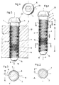
- the screw 1 consists of a shank 2 and a tool engagement part 23.
- the shank 2 is provided with a thread 3, it being possible here to use any type of thread shape, thread pitch or cross-sectional shape of a thread turn. It is also possible to use a fine thread or, for example, a trapezoidal thread or a sawtooth thread.
- the tool engagement part 23 has a round head 4, on the top of which an internal attack 5 is provided. All possible variations are also given with regard to the tool engagement part 23.
- the screw 1 itself can also be designed as a stud screw, ie without a head section, or but be provided with a corresponding screw head, which is provided with an internal or external tool attack.
- a first threaded section A with a circular cross-sectional shape and a second threaded section B with a trilobular cross-sectional shape of the same thickness are provided.
- the cross sections can be seen in FIGS. 2 and 3.
- the diameter D1 of the enveloping circle 7 in the first threaded section A is smaller than the diameter D2 of the enveloping circle 8 at the high points 9 of the threaded section B with a cross-sectional shape of the same thickness.
- the threads of both thread sections A and B have the same thread pitch S.
- the second threaded section B is provided with a trilobular cross-sectional shape of the same thickness.
- a "constant thickness” is understood to mean a geometrical body in which all diametrically opposite points on the outer diameter are at the same distance without the body being round.
- Such a geometric body can be produced with any precision by transverse rolling and has the advantage that if it is provided with a thread between rolling rolls or jaws or between thread rolls, it maintains its non-round shape and the thread depth - if necessary - is the same over the entire circumference.
- an odd number of high points 9 must therefore be provided, i.e. that a flattened area 10 must always be opposite one high point 9.
- the simplest form for the second threaded section B is given with a trilobular cross section, as is also shown in the cross section according to FIG. 3.
- the first threaded section A is adapted to the nut thread 11 in a corresponding workpiece 12 with normal play.
- the second threaded section B is adapted with a close fit to the nut thread 11 or with a slightly larger one Sleeve diameter executed. It can also be seen from FIG. 5 that there is the usual play 13 between the nut thread 11 and the threaded portion A, since the screw and nut threads must not have an overly tight fit by default, since when screwing in a screw in the usual sense not too large torques should be transmitted.
- the area of the threaded section B on the other hand, there is no longer any play between the nut thread 11 and the thread in the threaded section B in the area of the high points 9. This can be seen on the right side at the top in FIG. 5.
- a flattened area 10 is in use on the opposite side in FIG. 5, so that the corresponding play 13 results here.
- the three high points 9 are distributed directly around the circumference in the nut thread 11.
- the first threaded section A is longer in the axial direction than the second threaded section B. This avoids the need to apply excessive torque in order to screw in the screw 1. Thread section B, which runs over a few thread turns, is sufficient for optimal securing of the screw.
- a coating 14 consisting of an adhesive, lacquer or plastic is applied to a partial area of the threaded section A.
- a microencapsulated adhesive can also be used as a coating. It is also possible to apply this coating at any point on the threaded section A or at several successive points or in strips. However, it is also conceivable to additionally provide such a coating in the area of the threaded section B.
- the shaft 2 is conically tapered at its end 15 located at the front in the screwing-in direction 6. It is also provided that the end of the conical section ends with a spherical section-shaped cap 16.
- thread section A is still the first Thread section in the screw-in direction 6, since the threaded section B would never be screwed through the entire nut thread 11.
- the screw 1 is suitable for screwing in metal as well as in plastic or wood.
Landscapes
- Engineering & Computer Science (AREA)
- General Engineering & Computer Science (AREA)
- Mechanical Engineering (AREA)
- Reinforcement Elements For Buildings (AREA)
- Connection Of Plates (AREA)
- Dowels (AREA)
- Heterocyclic Compounds That Contain Two Or More Ring Oxygen Atoms (AREA)
- Polyesters Or Polycarbonates (AREA)
Claims (2)
- Vis avec sur au moins une partie de sa longueur une tige munie d'un filetage (3), où, vu dans le sens du vissage (6) de la vis (1) se trouvent successivement une première partie de filetage (A) à forme de section circulaire et une deuxième partie de filetage (B) avec une forme de section de même épaisseur, par exemple trilobulaire, et où le cercle enveloppe (7) de la partie (A) de filetage à forme de section circulaire est plus petit que le cercle enveloppe (8) dans les parties supérieures (9) de la partie de filetage (B) à forme de section de même épaisseur et les filets des deux parties de filetage (A, B) présentent le même pas (S), caractérisée en ce que la première partie de filetage (A) à forme de section circulaire et vue dans le sens axial de la tige (2) est plus longue que la deuxième partie de filetage (B) à forme de section de même épaisseur et que sur au moins un domaine partiel de la première partie de filetage (A) est déposé un revêtement (14) d'adhésif, de laque ou de matière plastique.
- Vis selon la revendication 1, caractérisée en ce que la tige (2) à son extrémité (15) antérieure dans le sens de vissage (6) se rétrécit en forme de cône et que l'extrémité de la partie conique se termine par une calotte sphérique (16).
Applications Claiming Priority (2)
| Application Number | Priority Date | Filing Date | Title |
|---|---|---|---|
| DE4111854 | 1991-04-11 | ||
| DE4111854A DE4111854C1 (fr) | 1991-04-11 | 1991-04-11 |
Publications (2)
| Publication Number | Publication Date |
|---|---|
| EP0508135A1 EP0508135A1 (fr) | 1992-10-14 |
| EP0508135B1 true EP0508135B1 (fr) | 1994-07-27 |
Family
ID=6429375
Family Applications (1)
| Application Number | Title | Priority Date | Filing Date |
|---|---|---|---|
| EP92104171A Expired - Lifetime EP0508135B1 (fr) | 1991-04-11 | 1992-03-11 | Vis |
Country Status (3)
| Country | Link |
|---|---|
| EP (1) | EP0508135B1 (fr) |
| AT (1) | ATE109253T1 (fr) |
| DE (2) | DE4111854C1 (fr) |
Families Citing this family (12)
| Publication number | Priority date | Publication date | Assignee | Title |
|---|---|---|---|---|
| DE4218975C3 (de) * | 1992-06-10 | 1998-07-09 | Rexroth Mannesmann Gmbh | Insbesondere als Bestandteil eines hydraulischen Gerätes vorgesehenes Gehäuse |
| DE19507715C1 (de) * | 1995-03-07 | 1996-08-01 | Mero Werke Kg | Vorrichtung zur Befestigung eines Bauteiles an einem Träger |
| DE29600973U1 (de) * | 1996-01-20 | 1996-03-21 | ITW Befestigungssysteme GmbH, 58642 Iserlohn | Befestigungsmittel für hochfeste Verbindung mit einem Untergrund |
| DE29721200U1 (de) * | 1997-11-29 | 1998-01-22 | Bümach Engineering International B.V., Emmen | Dichtende Gewindepaarung |
| DE19821160C1 (de) | 1998-05-12 | 1999-10-28 | Lemfoerder Lenksaeulen Gmbh | Befestigungssystem |
| DE102004034246B4 (de) * | 2004-07-15 | 2008-04-24 | Sfs Intec Holding Ag | Schraube |
| DE102006031298A1 (de) * | 2006-06-29 | 2008-01-03 | Swg Schraubenwerk Gaisbach Gmbh | Spanplattenschraube |
| DE102006031299A1 (de) * | 2006-06-29 | 2008-01-03 | Swg Schraubenwerk Gaisbach Gmbh | Spanplattenschraube |
| AT13123U1 (de) | 2011-07-15 | 2013-06-15 | Johannes Duscheck | Schraube, insbesondere für den Holzbau |
| DE102012015307B4 (de) * | 2012-07-31 | 2015-03-05 | Man Truck & Bus Ag | Korrosionsgeschützter Bolzen |
| DE102014003197A1 (de) * | 2014-03-04 | 2015-09-10 | GM Global Technology Operations LLC (n. d. Ges. d. Staates Delaware) | Finde-Gewinde |
| DE102014226015A1 (de) | 2014-12-16 | 2016-06-16 | Arnold Umformtechnik Gmbh & Co. Kg | Schraube und Verwendung einer Schraube |
Family Cites Families (7)
| Publication number | Priority date | Publication date | Assignee | Title |
|---|---|---|---|---|
| US2301181A (en) * | 1941-10-23 | 1942-11-10 | Eric M Ilsemann | Self-locking threaded fastening element |
| NL129061C (fr) * | 1963-07-18 | |||
| BE757278R (fr) * | 1965-08-02 | 1971-03-16 | Ncr Co | Dispositif de |
| US3461470A (en) * | 1966-07-07 | 1969-08-19 | Fastron Co | Thread-forming screw and method of making the same |
| US3426820A (en) * | 1967-10-05 | 1969-02-11 | Res Eng & Mfg | High friction screw |
| DE2157373A1 (de) * | 1970-11-23 | 1972-05-25 | Textron Inc | Selbsthaltendes Befestigungselement und Werkzeug zu seiner Herstellung |
| GB2198801B (en) * | 1986-12-19 | 1991-02-20 | Masco Ind Inc | Locking fastener |
-
1991
- 1991-04-11 DE DE4111854A patent/DE4111854C1/de not_active Expired - Fee Related
-
1992
- 1992-03-11 EP EP92104171A patent/EP0508135B1/fr not_active Expired - Lifetime
- 1992-03-11 AT AT92104171T patent/ATE109253T1/de not_active IP Right Cessation
- 1992-03-11 DE DE59200308T patent/DE59200308D1/de not_active Expired - Fee Related
Also Published As
| Publication number | Publication date |
|---|---|
| DE4111854C1 (fr) | 1992-06-17 |
| DE59200308D1 (de) | 1994-09-01 |
| ATE109253T1 (de) | 1994-08-15 |
| EP0508135A1 (fr) | 1992-10-14 |
Similar Documents
| Publication | Publication Date | Title |
|---|---|---|
| DE19900791B4 (de) | Verbindungselement für zwei Maschinen- oder Bauteile insbesondere Paß-Dehnschraube, Paß-Gewindebolzen o. dgl. | |
| EP2032864B1 (fr) | Rondelle et assemblage à vis pourvu de ladite rondelle | |
| WO2008011950A1 (fr) | Dispositif de fixation d'une pièce rapportée et d'une pièce de support à distance l'une de l'autre | |
| EP0443134A1 (fr) | Douille filetée | |
| EP0508135B1 (fr) | Vis | |
| DE19615191C2 (de) | Schraube und Verfahren zur drehmomentbegrenzten Befestigung von Metall- und/oder Kunststoffprofilen oder -platten auf einem Unterbau | |
| EP2982874B1 (fr) | Bossage pour vis destine a la fixation d'un composant | |
| EP0273863A1 (fr) | Boulons et pièce opposée | |
| EP0534001A1 (fr) | Assemblage à vis pour assembler deux pièces de construction, qui ont vue distance, notamment des plaques de métal | |
| EP2044341A1 (fr) | Écrou de blocage | |
| EP1276996B1 (fr) | Unite de montage constituee d'un composant et d'au moins une vis taraudeuse | |
| EP3374649B1 (fr) | Vis autotaraudeuse | |
| EP0703394A1 (fr) | Collier de serrage | |
| EP1589236A1 (fr) | Système de fixation pour connecter des barres profilées | |
| DE102006047673B4 (de) | Einschraubwerkzeug | |
| EP2811181B1 (fr) | Vis | |
| DE29508741U1 (de) | Befestigungsanker sowie System aus Befestigungsanker und Bauelement | |
| DE3203031A1 (de) | Laengenveraenderliches justiergestaenge | |
| DE102017002069A1 (de) | Einschraubdübel und Befestigungssystem mit einem Einschraubdübel | |
| AT407778B (de) | Schraube zur befestigung mindestens eines ersten bauteiles an einem zweiten bauteil | |
| DE19525733C2 (de) | Blechschraube | |
| DE19527602A1 (de) | Vorrichtung zum Befestigen von Gegenständen | |
| DE29724014U1 (de) | Montage-Baugruppe | |
| DE8908118U1 (de) | Vorrichtung zur Befestigung einer nachgiebigen Materialschicht an einer Unterkonstruktion | |
| DE2125999C (de) | Spannschloß zum Spannen elektrischer Freileitungen |
Legal Events
| Date | Code | Title | Description |
|---|---|---|---|
| PUAI | Public reference made under article 153(3) epc to a published international application that has entered the european phase |
Free format text: ORIGINAL CODE: 0009012 |
|
| AK | Designated contracting states |
Kind code of ref document: A1 Designated state(s): AT BE CH DE DK ES FR GB IT LI LU NL PT SE |
|
| 17P | Request for examination filed |
Effective date: 19921031 |
|
| 17Q | First examination report despatched |
Effective date: 19931027 |
|
| RAP1 | Party data changed (applicant data changed or rights of an application transferred) |
Owner name: SFS INDUSTRIE HOLDING AG |
|
| GRAA | (expected) grant |
Free format text: ORIGINAL CODE: 0009210 |
|
| AK | Designated contracting states |
Kind code of ref document: B1 Designated state(s): AT BE CH DE DK ES FR GB IT LI LU NL PT SE |
|
| PG25 | Lapsed in a contracting state [announced via postgrant information from national office to epo] |
Ref country code: IT Free format text: LAPSE BECAUSE OF FAILURE TO SUBMIT A TRANSLATION OF THE DESCRIPTION OR TO PAY THE FEE WITHIN THE PRE;WARNING: LAPSES OF ITALIAN PATENTS WITH EFFECTIVE DATE BEFORE 2007 MAY HAVE OCCURRED AT ANY TIME BEFORE 2007. THE CORRECT EFFECTIVE DATE MAY BE DIFFERENT FROM THE ONE RECORDED.SCRIBED TIME-LIMIT Effective date: 19940727 Ref country code: ES Free format text: THE PATENT HAS BEEN ANNULLED BY A DECISION OF A NATIONAL AUTHORITY Effective date: 19940727 Ref country code: BE Effective date: 19940727 Ref country code: GB Effective date: 19940727 Ref country code: NL Effective date: 19940727 Ref country code: DK Effective date: 19940727 Ref country code: FR Effective date: 19940727 |
|
| REF | Corresponds to: |
Ref document number: 109253 Country of ref document: AT Date of ref document: 19940815 Kind code of ref document: T |
|
| REF | Corresponds to: |
Ref document number: 59200308 Country of ref document: DE Date of ref document: 19940901 |
|
| PG25 | Lapsed in a contracting state [announced via postgrant information from national office to epo] |
Ref country code: SE Effective date: 19941027 Ref country code: PT Effective date: 19941027 |
|
| EN | Fr: translation not filed | ||
| NLV1 | Nl: lapsed or annulled due to failure to fulfill the requirements of art. 29p and 29m of the patents act | ||
| GBV | Gb: ep patent (uk) treated as always having been void in accordance with gb section 77(7)/1977 [no translation filed] |
Effective date: 19940727 |
|
| PG25 | Lapsed in a contracting state [announced via postgrant information from national office to epo] |
Ref country code: AT Effective date: 19950311 |
|
| PG25 | Lapsed in a contracting state [announced via postgrant information from national office to epo] |
Ref country code: LI Effective date: 19950331 Ref country code: CH Effective date: 19950331 Ref country code: LU Free format text: LAPSE BECAUSE OF NON-PAYMENT OF DUE FEES Effective date: 19950331 |
|
| PLBE | No opposition filed within time limit |
Free format text: ORIGINAL CODE: 0009261 |
|
| STAA | Information on the status of an ep patent application or granted ep patent |
Free format text: STATUS: NO OPPOSITION FILED WITHIN TIME LIMIT |
|
| 26N | No opposition filed | ||
| REG | Reference to a national code |
Ref country code: CH Ref legal event code: PL |
|
| PG25 | Lapsed in a contracting state [announced via postgrant information from national office to epo] |
Ref country code: DE Effective date: 19951201 |