EP2811181B1 - Vis - Google Patents
Vis Download PDFInfo
- Publication number
- EP2811181B1 EP2811181B1 EP14168304.5A EP14168304A EP2811181B1 EP 2811181 B1 EP2811181 B1 EP 2811181B1 EP 14168304 A EP14168304 A EP 14168304A EP 2811181 B1 EP2811181 B1 EP 2811181B1
- Authority
- EP
- European Patent Office
- Prior art keywords
- screw
- thread
- angle
- degrees
- flank
- Prior art date
- Legal status (The legal status is an assumption and is not a legal conclusion. Google has not performed a legal analysis and makes no representation as to the accuracy of the status listed.)
- Active
Links
Images

Classifications
-
- F—MECHANICAL ENGINEERING; LIGHTING; HEATING; WEAPONS; BLASTING
- F16—ENGINEERING ELEMENTS AND UNITS; GENERAL MEASURES FOR PRODUCING AND MAINTAINING EFFECTIVE FUNCTIONING OF MACHINES OR INSTALLATIONS; THERMAL INSULATION IN GENERAL
- F16B—DEVICES FOR FASTENING OR SECURING CONSTRUCTIONAL ELEMENTS OR MACHINE PARTS TOGETHER, e.g. NAILS, BOLTS, CIRCLIPS, CLAMPS, CLIPS OR WEDGES; JOINTS OR JOINTING
- F16B25/00—Screws that cut thread in the body into which they are screwed, e.g. wood screws
- F16B25/0036—Screws that cut thread in the body into which they are screwed, e.g. wood screws characterised by geometric details of the screw
- F16B25/0042—Screws that cut thread in the body into which they are screwed, e.g. wood screws characterised by geometric details of the screw characterised by the geometry of the thread, the thread being a ridge wrapped around the shaft of the screw
- F16B25/0047—Screws that cut thread in the body into which they are screwed, e.g. wood screws characterised by geometric details of the screw characterised by the geometry of the thread, the thread being a ridge wrapped around the shaft of the screw the ridge being characterised by its cross-section in the plane of the shaft axis
-
- F—MECHANICAL ENGINEERING; LIGHTING; HEATING; WEAPONS; BLASTING
- F16—ENGINEERING ELEMENTS AND UNITS; GENERAL MEASURES FOR PRODUCING AND MAINTAINING EFFECTIVE FUNCTIONING OF MACHINES OR INSTALLATIONS; THERMAL INSULATION IN GENERAL
- F16B—DEVICES FOR FASTENING OR SECURING CONSTRUCTIONAL ELEMENTS OR MACHINE PARTS TOGETHER, e.g. NAILS, BOLTS, CIRCLIPS, CLAMPS, CLIPS OR WEDGES; JOINTS OR JOINTING
- F16B25/00—Screws that cut thread in the body into which they are screwed, e.g. wood screws
- F16B25/001—Screws that cut thread in the body into which they are screwed, e.g. wood screws characterised by the material of the body into which the screw is screwed
- F16B25/0015—Screws that cut thread in the body into which they are screwed, e.g. wood screws characterised by the material of the body into which the screw is screwed the material being a soft organic material, e.g. wood or plastic
-
- F—MECHANICAL ENGINEERING; LIGHTING; HEATING; WEAPONS; BLASTING
- F16—ENGINEERING ELEMENTS AND UNITS; GENERAL MEASURES FOR PRODUCING AND MAINTAINING EFFECTIVE FUNCTIONING OF MACHINES OR INSTALLATIONS; THERMAL INSULATION IN GENERAL
- F16B—DEVICES FOR FASTENING OR SECURING CONSTRUCTIONAL ELEMENTS OR MACHINE PARTS TOGETHER, e.g. NAILS, BOLTS, CIRCLIPS, CLAMPS, CLIPS OR WEDGES; JOINTS OR JOINTING
- F16B25/00—Screws that cut thread in the body into which they are screwed, e.g. wood screws
- F16B25/001—Screws that cut thread in the body into which they are screwed, e.g. wood screws characterised by the material of the body into which the screw is screwed
- F16B25/0021—Screws that cut thread in the body into which they are screwed, e.g. wood screws characterised by the material of the body into which the screw is screwed the material being metal, e.g. sheet-metal or aluminium
Definitions
- the invention relates to a screw with a screw shaft which extends from a screw drive end, which has for example a screw head, to a screw tip, and which has a thread.
- both thread flanks are straight in a longitudinal section through the screw.
- the side contour of the screw core between the thread flanks is in most cases rectilinear and parallel to the longitudinal axis of the screw.
- the screw drive end facing the thread flank is closer to a transverse plane to the longitudinal axis of the screw than the opposite thread flank.
- a thread-forming screw for use in soft material is already known, in which the thread flank facing away from the screw drive end is partially concave and merges rounded into the opposite thread flank ( US 2009/0047095 A1 ).
- the invention is based on the object to provide a screw with a higher thread stability and a reduced screw-in. It should be a chipboard screw or a screw, which can also be used in plastic, metal, solid wood and other materials.
- the thread flanks are curved or curved in section, specifically the thread flank facing the screw drive end convexly curved, and the opposite thread flank facing the front screw end concavely curved.
- the thread flank facing the screw drive end merges into the screw shank substantially at right angles to the transition into the screw shank, at most slightly above a right angle to allow the manufacture of the thread by means of rolling dies.
- the front end of the screw facing flank merges obliquely into the screw shaft, so that the angle between the thread flank and the outer contour of the threaded shaft forms an obtuse angle, which is for example in a range of 130 to 160 degrees ,
- the two thread flanks meet in the thread edge, wherein instead of a sharp thread edge a flattening surface may be provided, the tangents to the respective thread flank then form an acute angle, which is for example in the range of 20 to 30 degrees, preferably at an angle of about 25 angular degrees.
- the curvature of the thread flanks can correspond to any curve. However, it has proved to be particularly advantageous if the curvature of the screw drive end facing the thread flank and / or the curvature of the front end of the screw facing the thread flank corresponds to a circular arc, ie a curvature with a constant radius.
- the thread flanks extend along a parabola, generally along a curve or along a string of straight stretches fitted into a camber.
- the radius of curvature of the concave curved thread flank is in a range between 30% and 50%, in particular 36% and 46%, of the core diameter of the screw.
- this radius of curvature of the concave thread flank is in a range between 20% and 30%, in particular 23% and 28%, of the outer diameter of the thread of the screw.
- the radius of curvature of the convexly curved thread flank in a range between 90% and 170%, in particular 130% and 165% or 90% and 95%, of the core diameter of the screw.
- the radius of curvature of the convexly curved thread flank is in the range of 60% to 100%, in particular 60% to 63% or 80% to 100%, of the outer diameter of the thread of the screw.
- the ratio of the outer diameter of the thread of the screw to the core diameter of the screw at about 1.5, in particular between 1.45 and 1.7, is located.
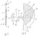
- the FIG. 1 shows a side view of a chipboard screw.
- the chipboard screw contains a screw body or screw shank 1, at one end 2 of which a screw head 3 is formed. It is a countersunk head.
- a screw head 3 In the flat end face 4 of the screw head 3 a not visible in the figure screw driving recess is arranged, with the aid of which the screw can be rotated.
- the screw body 1 forms at its, the screw head 3 remote from the front ends 6 a screw tip 5, which is a drill bit.
- the screw body 1 initially has a smooth shank portion 7, which is therefore designed to be thread-free.
- a milling section 8 in which a series of very steep ribs is arranged to facilitate screwing the screw into fibrous material.
- Such a milling section 8 can, as shown, be provided in a part-threaded screw, but also in a full-threaded screw.
- the threads of the thread 9 have a measured distance in the axial direction from each other, so that the outer contour 10 of the screw body 1 stops between the threads.
- the screw has a core diameter 11 and an outer diameter 12 of the thread, which is for example 50% larger than the core diameter 11.
- FIG. 2 shows a longitudinal section through the screw, the core 13 is shown on the right and the thread profile on the left.
- upwardly directed thread flank 14 is thus that thread flank which faces the screw head 3, while the lower thread flank 15 faces the front screw end 6 with the screw tip 5.
- the extending in this longitudinal section through the screw contour of the thread flank 14 is located on a circular arc with a radius 16. It goes into the outer contour 10 of the screw core 13 at an angle opposite, which is slightly larger than a right angle.
- the tangent 17 to the convexly curved upper thread flank 14 closes with the outer contour 10 of the screw at an angle 18 of just below 90 °.
- the contour of the front end of the screw 6 facing thread flank 15 is also located on a circular arc with a radius 19th
- a tangent 20 to the concave thread flank 15 at the point of transition into the outer contour 10 closes with this outer contour 10 an angle 21 a.
- This angle 21 is in a range of about 30 to 33 degrees.
- the curved thread flank 15 merges at an obtuse angle into the outer contour 10 of the screw, in the illustrated embodiment the angle is 147 to 150 degrees.
- the radius 16 of the curvature of the contour of the convexly curved thread flank 14 is in the illustrated embodiment at a value of about 92% of the core diameter 11 or at a value of about 61% of the outer diameter 12 of the thread of the screw.
- the radius of curvature 19 of the contour of the concave thread flank 15 is at a value of about 35% of the core diameter 11 or at a value of about 23% of the outer diameter 12 of the thread of the screw.
- the two thread flanks 14, 15 meet to form a thread edge 22.
- the tangent 23 to the screw head facing the thread flank 14 and the tangent 24 to the front end of the screw 6 facing thread flank 15 form at the thread edge an angle 25, which is approximately at 25 ° lies.
- a narrow flattening surface may also be provided, so that the thread edge 22 is then replaced by two side edges running parallel to the thread edge 22 and the narrow flattening surface extending therebetween.
- FIG. 3 shows a further embodiment according to the invention of a screw 30, which is approximately identical to the screw of Fig. 1 and 2 is constructed so that only the in Fig. 4 identifiable differences are explained below.
- the Fig. 4 shows a sectional view of the detail A of Fig. 3 ,
- the convex thread flank 14 and the concave thread flank 15 do not meet in a common thread edge 22, as in the screw according to FIG Fig. 1 and Fig. 2 but the thread flanks 14, 15 terminate at a common flattening surface 30 which is approximately parallel runs to the central longitudinal axis of the screw.
- the flattening surface 30 may be provided for production reasons.
- the screw drive end facing the convex thread flank 14 thus ends at an edge 31, which forms a side edge of the flattening surface 30 at the same time.
- the screw tip facing concave thread flank 15 terminates at an edge 32, which simultaneously forms another side edge of the flattening surface 30.
- edges 31, 32 run parallel to one another and enclose the flattening surface 30 between them.
- the flattening surface 30 and its side edges 31, 32 are parallel to an imaginary thread edge 33 which extends radially outside the flattening surface 30 and in which the tangents 23, 24 meet the thread flanks 14, 15 in their respective edges 31, 32.
- the tangents 23, 24 meet at an angle of 20 to 25 degrees, in the embodiment of the Fig. 4 at an angle of about 21 °.
- An angle 34, the tangent to the screw tip facing the concave thread flank 15 applied tangent 24 includes a running through the imaginary thread edge 33 perpendicular to the central longitudinal axis of the screw longitudinal axis is in the illustrated embodiment about 7 °.
- a height H of the flattening surface 30 is about 0.2 mm in the illustrated embodiment.
Landscapes
- Engineering & Computer Science (AREA)
- General Engineering & Computer Science (AREA)
- Physics & Mathematics (AREA)
- Geometry (AREA)
- Mechanical Engineering (AREA)
- Golf Clubs (AREA)
- Transmission Devices (AREA)
Claims (6)
- Vis, comprenant- un corps de vis essentiellement cylindrique (1),- qui s'étend depuis une extrémité d'entraînement de vis (2) jusqu'à une extrémité avant de vis (6), et comprenant- un filet de vis (9) s'étendant sur au moins une partie du corps de vis (1) jusqu'à l'extrémité avant de vis (6),- dont le flanc de filet (14) tourné vers l'extrémité d'entraînement de vis (2) présente une courbure convexe et- dont le flanc de filet (15) opposé à l'extrémité d'entraînement de vis (2) présente une courbure concave,caractérisée en ce que- le flanc de filet (14) tourné vers l'extrémité d'entraînement de vis (2) se prolonge approximativement à angle droit ou en variante suivant un angle compris entre 85° et 90° dans la tige de vis (13) et- les deux flancs de filet (14, 15) se rejoignent au niveau de l'arête de filet (22) en formant un angle (25) de 20° à 25°, en particulier de 25°, ou- se terminent au niveau d'une surface aplatie (30) et des tangentes (23, 24) aux deux flancs de filet (14, 15) se rejoignent dans une arête de filet imaginaire (33) radialement à l'extérieur de la surface aplatie (30) en formant un angle compris entre 20° et 25°, en particulier de 21°.
- Vis selon la revendication 1, dans laquelle le flanc de filet (15) opposé à l'extrémité d'entraînement de vis (2) se prolonge suivant un angle obtus dans la tige de vis (13).
- Vis selon l'une quelconque des revendications précédentes, dans laquelle la courbure du flanc de filet (14) tourné vers l'extrémité d'entraînement de vis (2) et/ou du flanc de filet (15) opposé à l'extrémité d'entraînement de vis (2) correspond à un arc de cercle, à une parabole ou à une série de sections rectilignes qui suivent une allure courbe.
- Vis selon l'une quelconque des revendications précédentes, dans laquelle le rayon de courbure (19) du flanc de filet (15) tourné vers l'extrémité avant de vis (6) vaut entre 30 % et 50 %, en particulier entre 36 % et 46 %, du diamètre de noyau (11) de la vis et/ou entre 20 % et 30 %, en particulier entre 23 % et 28 % du diamètre extérieur (12) du filet (9) de la vis.
- Vis selon l'une quelconque des revendications précédentes, dans laquelle le rayon de courbure (16) du flanc de filet (14) tourné vers l'extrémité d'entraînement de vis (2) vaut entre 90 % et 170 %, en particulier entre 130 % et 165 % ou entre 90 % et 95 % du diamètre de noyau (11) et/ou entre 60 % et 100 %, en particulier entre 60 % et 63 % ou entre 90 % et 100 %, du diamètre extérieur (12) du filet (9) de la vis.
- Vis selon l'une quelconque des revendications précédentes, dans laquelle le rapport du diamètre extérieur (12) du filet (9) au diamètre de noyau de la vis vaut environ 1,5, en particulier est compris entre 1,45 et 1,7.
Applications Claiming Priority (1)
| Application Number | Priority Date | Filing Date | Title |
|---|---|---|---|
| DE201310210566 DE102013210566A1 (de) | 2013-06-06 | 2013-06-06 | Schraube |
Publications (2)
| Publication Number | Publication Date |
|---|---|
| EP2811181A1 EP2811181A1 (fr) | 2014-12-10 |
| EP2811181B1 true EP2811181B1 (fr) | 2017-07-05 |
Family
ID=50687414
Family Applications (1)
| Application Number | Title | Priority Date | Filing Date |
|---|---|---|---|
| EP14168304.5A Active EP2811181B1 (fr) | 2013-06-06 | 2014-05-14 | Vis |
Country Status (2)
| Country | Link |
|---|---|
| EP (1) | EP2811181B1 (fr) |
| DE (1) | DE102013210566A1 (fr) |
Cited By (1)
| Publication number | Priority date | Publication date | Assignee | Title |
|---|---|---|---|---|
| USD1079456S1 (en) | 2022-12-16 | 2025-06-17 | Primesource Building Products, Inc. | Screw head |
Families Citing this family (1)
| Publication number | Priority date | Publication date | Assignee | Title |
|---|---|---|---|---|
| DE102021126035B4 (de) | 2021-10-07 | 2025-03-27 | MFI-Metall Fastening Industrie GmbH | Holzschraube |
Family Cites Families (7)
| Publication number | Priority date | Publication date | Assignee | Title |
|---|---|---|---|---|
| US1336773A (en) * | 1916-12-14 | 1920-04-13 | Caldweil John William | Screw |
| US3459250A (en) * | 1967-04-14 | 1969-08-05 | Burdsall Russell & Ward Bolt & | Prevailing-torque lockscrews |
| US3523565A (en) * | 1968-04-29 | 1970-08-11 | Allied Prod Corp | Self locking male threaded fastener |
| DE2157373A1 (de) * | 1970-11-23 | 1972-05-25 | Textron Inc | Selbsthaltendes Befestigungselement und Werkzeug zu seiner Herstellung |
| DE8103990U1 (de) * | 1981-02-13 | 1982-09-30 | Jaeger Eberhard Gmbh & Co Kg, 5928 Laasphe | Selbstfurchende Schraube |
| WO2006043169A1 (fr) * | 2004-10-22 | 2006-04-27 | Ajax Cooke Pty Ltd | Vis et systeme de fixation pour blindage |
| WO2009023168A2 (fr) * | 2007-08-13 | 2009-02-19 | Research Engineering & Manufacturing, Inc. | Pièce de fixation formant filet |
-
2013
- 2013-06-06 DE DE201310210566 patent/DE102013210566A1/de not_active Withdrawn
-
2014
- 2014-05-14 EP EP14168304.5A patent/EP2811181B1/fr active Active
Cited By (1)
| Publication number | Priority date | Publication date | Assignee | Title |
|---|---|---|---|---|
| USD1079456S1 (en) | 2022-12-16 | 2025-06-17 | Primesource Building Products, Inc. | Screw head |
Also Published As
| Publication number | Publication date |
|---|---|
| DE102013210566A1 (de) | 2014-12-11 |
| EP2811181A1 (fr) | 2014-12-10 |
Similar Documents
| Publication | Publication Date | Title |
|---|---|---|
| DE102004021484B4 (de) | Verfahren zum Herstellen einer Verbindungsanordnung | |
| EP0869287B1 (fr) | Elément de fixation autopoinçonneur et autotaraudeur | |
| DE4333791C2 (de) | Gewindeschneidschraube | |
| EP1568901B1 (fr) | Vis autotaraudeuse | |
| WO2010003901A1 (fr) | Vis | |
| DE102010000702A1 (de) | Gewindeformende Schraube und ihre Verwendung | |
| EP2012026A2 (fr) | Vis | |
| AT412665B (de) | Schraube zur verwendung bei aus holz hergestellten bauteilen | |
| EP3377777B1 (fr) | Vis de formage de filets ou de taraudage, en particulier pour utilisation dans du métal léger | |
| EP3655669B1 (fr) | Vis à bois | |
| DE102014000940A1 (de) | Schraube, Befestigungsanordnung und Verwendung einer Schraube | |
| EP2150709B1 (fr) | Vis pour panneaux de particules | |
| EP1718876B1 (fr) | Vis autotaraudeuse | |
| DE19525732A1 (de) | Schraube | |
| DE19632838A1 (de) | Schraube mit einer selbstbohrenden Spitze | |
| EP0504782B1 (fr) | Vis, procédé et matrice de laminage pour sa fabrication | |
| EP2811181B1 (fr) | Vis | |
| EP3374649B1 (fr) | Vis autotaraudeuse | |
| DE102017002069B4 (de) | Befestigungssystem mit einem Einschraubdübel | |
| EP3426937B1 (fr) | Vis | |
| DE3046692C2 (de) | Gewindefurchende Schraube | |
| DE19541839A1 (de) | Selbstschneidende Schraube | |
| DE3923091A1 (de) | Senkkopfschraube | |
| EP3542076B1 (fr) | Vis à bois et procédé de fabrication d'une vis à bois | |
| EP1873405A2 (fr) | Vis pour panneau aggloméré |
Legal Events
| Date | Code | Title | Description |
|---|---|---|---|
| PUAI | Public reference made under article 153(3) epc to a published international application that has entered the european phase |
Free format text: ORIGINAL CODE: 0009012 |
|
| 17P | Request for examination filed |
Effective date: 20140514 |
|
| AK | Designated contracting states |
Kind code of ref document: A1 Designated state(s): AL AT BE BG CH CY CZ DE DK EE ES FI FR GB GR HR HU IE IS IT LI LT LU LV MC MK MT NL NO PL PT RO RS SE SI SK SM TR |
|
| AX | Request for extension of the european patent |
Extension state: BA ME |
|
| R17P | Request for examination filed (corrected) |
Effective date: 20141223 |
|
| RBV | Designated contracting states (corrected) |
Designated state(s): AL AT BE BG CH CY CZ DE DK EE ES FI FR GB GR HR HU IE IS IT LI LT LU LV MC MK MT NL NO PL PT RO RS SE SI SK SM TR |
|
| GRAP | Despatch of communication of intention to grant a patent |
Free format text: ORIGINAL CODE: EPIDOSNIGR1 |
|
| INTG | Intention to grant announced |
Effective date: 20170105 |
|
| GRAS | Grant fee paid |
Free format text: ORIGINAL CODE: EPIDOSNIGR3 |
|
| GRAA | (expected) grant |
Free format text: ORIGINAL CODE: 0009210 |
|
| AK | Designated contracting states |
Kind code of ref document: B1 Designated state(s): AL AT BE BG CH CY CZ DE DK EE ES FI FR GB GR HR HU IE IS IT LI LT LU LV MC MK MT NL NO PL PT RO RS SE SI SK SM TR |
|
| REG | Reference to a national code |
Ref country code: GB Ref legal event code: FG4D Free format text: NOT ENGLISH |
|
| REG | Reference to a national code |
Ref country code: CH Ref legal event code: EP Ref country code: CH Ref legal event code: NV Representative=s name: DR. LUSUARDI AG, CH |
|
| REG | Reference to a national code |
Ref country code: AT Ref legal event code: REF Ref document number: 906814 Country of ref document: AT Kind code of ref document: T Effective date: 20170715 |
|
| REG | Reference to a national code |
Ref country code: IE Ref legal event code: FG4D Free format text: LANGUAGE OF EP DOCUMENT: GERMAN |
|
| REG | Reference to a national code |
Ref country code: DE Ref legal event code: R096 Ref document number: 502014004465 Country of ref document: DE |
|
| REG | Reference to a national code |
Ref country code: NL Ref legal event code: MP Effective date: 20170705 |
|
| REG | Reference to a national code |
Ref country code: LT Ref legal event code: MG4D |
|
| PG25 | Lapsed in a contracting state [announced via postgrant information from national office to epo] |
Ref country code: HR Free format text: LAPSE BECAUSE OF FAILURE TO SUBMIT A TRANSLATION OF THE DESCRIPTION OR TO PAY THE FEE WITHIN THE PRESCRIBED TIME-LIMIT Effective date: 20170705 Ref country code: NL Free format text: LAPSE BECAUSE OF FAILURE TO SUBMIT A TRANSLATION OF THE DESCRIPTION OR TO PAY THE FEE WITHIN THE PRESCRIBED TIME-LIMIT Effective date: 20170705 Ref country code: NO Free format text: LAPSE BECAUSE OF FAILURE TO SUBMIT A TRANSLATION OF THE DESCRIPTION OR TO PAY THE FEE WITHIN THE PRESCRIBED TIME-LIMIT Effective date: 20171005 Ref country code: LT Free format text: LAPSE BECAUSE OF FAILURE TO SUBMIT A TRANSLATION OF THE DESCRIPTION OR TO PAY THE FEE WITHIN THE PRESCRIBED TIME-LIMIT Effective date: 20170705 Ref country code: FI Free format text: LAPSE BECAUSE OF FAILURE TO SUBMIT A TRANSLATION OF THE DESCRIPTION OR TO PAY THE FEE WITHIN THE PRESCRIBED TIME-LIMIT Effective date: 20170705 Ref country code: SE Free format text: LAPSE BECAUSE OF FAILURE TO SUBMIT A TRANSLATION OF THE DESCRIPTION OR TO PAY THE FEE WITHIN THE PRESCRIBED TIME-LIMIT Effective date: 20170705 |
|
| PG25 | Lapsed in a contracting state [announced via postgrant information from national office to epo] |
Ref country code: RS Free format text: LAPSE BECAUSE OF FAILURE TO SUBMIT A TRANSLATION OF THE DESCRIPTION OR TO PAY THE FEE WITHIN THE PRESCRIBED TIME-LIMIT Effective date: 20170705 Ref country code: LV Free format text: LAPSE BECAUSE OF FAILURE TO SUBMIT A TRANSLATION OF THE DESCRIPTION OR TO PAY THE FEE WITHIN THE PRESCRIBED TIME-LIMIT Effective date: 20170705 Ref country code: GR Free format text: LAPSE BECAUSE OF FAILURE TO SUBMIT A TRANSLATION OF THE DESCRIPTION OR TO PAY THE FEE WITHIN THE PRESCRIBED TIME-LIMIT Effective date: 20171006 Ref country code: BG Free format text: LAPSE BECAUSE OF FAILURE TO SUBMIT A TRANSLATION OF THE DESCRIPTION OR TO PAY THE FEE WITHIN THE PRESCRIBED TIME-LIMIT Effective date: 20171005 Ref country code: ES Free format text: LAPSE BECAUSE OF FAILURE TO SUBMIT A TRANSLATION OF THE DESCRIPTION OR TO PAY THE FEE WITHIN THE PRESCRIBED TIME-LIMIT Effective date: 20170705 Ref country code: PL Free format text: LAPSE BECAUSE OF FAILURE TO SUBMIT A TRANSLATION OF THE DESCRIPTION OR TO PAY THE FEE WITHIN THE PRESCRIBED TIME-LIMIT Effective date: 20170705 Ref country code: IS Free format text: LAPSE BECAUSE OF FAILURE TO SUBMIT A TRANSLATION OF THE DESCRIPTION OR TO PAY THE FEE WITHIN THE PRESCRIBED TIME-LIMIT Effective date: 20171105 |
|
| REG | Reference to a national code |
Ref country code: DE Ref legal event code: R097 Ref document number: 502014004465 Country of ref document: DE |
|
| PG25 | Lapsed in a contracting state [announced via postgrant information from national office to epo] |
Ref country code: RO Free format text: LAPSE BECAUSE OF FAILURE TO SUBMIT A TRANSLATION OF THE DESCRIPTION OR TO PAY THE FEE WITHIN THE PRESCRIBED TIME-LIMIT Effective date: 20170705 Ref country code: DK Free format text: LAPSE BECAUSE OF FAILURE TO SUBMIT A TRANSLATION OF THE DESCRIPTION OR TO PAY THE FEE WITHIN THE PRESCRIBED TIME-LIMIT Effective date: 20170705 Ref country code: CZ Free format text: LAPSE BECAUSE OF FAILURE TO SUBMIT A TRANSLATION OF THE DESCRIPTION OR TO PAY THE FEE WITHIN THE PRESCRIBED TIME-LIMIT Effective date: 20170705 |
|
| PLBE | No opposition filed within time limit |
Free format text: ORIGINAL CODE: 0009261 |
|
| STAA | Information on the status of an ep patent application or granted ep patent |
Free format text: STATUS: NO OPPOSITION FILED WITHIN TIME LIMIT |
|
| REG | Reference to a national code |
Ref country code: FR Ref legal event code: PLFP Year of fee payment: 5 |
|
| PG25 | Lapsed in a contracting state [announced via postgrant information from national office to epo] |
Ref country code: EE Free format text: LAPSE BECAUSE OF FAILURE TO SUBMIT A TRANSLATION OF THE DESCRIPTION OR TO PAY THE FEE WITHIN THE PRESCRIBED TIME-LIMIT Effective date: 20170705 Ref country code: SM Free format text: LAPSE BECAUSE OF FAILURE TO SUBMIT A TRANSLATION OF THE DESCRIPTION OR TO PAY THE FEE WITHIN THE PRESCRIBED TIME-LIMIT Effective date: 20170705 Ref country code: SK Free format text: LAPSE BECAUSE OF FAILURE TO SUBMIT A TRANSLATION OF THE DESCRIPTION OR TO PAY THE FEE WITHIN THE PRESCRIBED TIME-LIMIT Effective date: 20170705 Ref country code: IT Free format text: LAPSE BECAUSE OF FAILURE TO SUBMIT A TRANSLATION OF THE DESCRIPTION OR TO PAY THE FEE WITHIN THE PRESCRIBED TIME-LIMIT Effective date: 20170705 |
|
| 26N | No opposition filed |
Effective date: 20180406 |
|
| PG25 | Lapsed in a contracting state [announced via postgrant information from national office to epo] |
Ref country code: SI Free format text: LAPSE BECAUSE OF FAILURE TO SUBMIT A TRANSLATION OF THE DESCRIPTION OR TO PAY THE FEE WITHIN THE PRESCRIBED TIME-LIMIT Effective date: 20170705 |
|
| PG25 | Lapsed in a contracting state [announced via postgrant information from national office to epo] |
Ref country code: MT Free format text: LAPSE BECAUSE OF FAILURE TO SUBMIT A TRANSLATION OF THE DESCRIPTION OR TO PAY THE FEE WITHIN THE PRESCRIBED TIME-LIMIT Effective date: 20170705 |
|
| GBPC | Gb: european patent ceased through non-payment of renewal fee |
Effective date: 20180514 |
|
| REG | Reference to a national code |
Ref country code: BE Ref legal event code: MM Effective date: 20180531 |
|
| PG25 | Lapsed in a contracting state [announced via postgrant information from national office to epo] |
Ref country code: MC Free format text: LAPSE BECAUSE OF FAILURE TO SUBMIT A TRANSLATION OF THE DESCRIPTION OR TO PAY THE FEE WITHIN THE PRESCRIBED TIME-LIMIT Effective date: 20170705 |
|
| REG | Reference to a national code |
Ref country code: IE Ref legal event code: MM4A |
|
| PG25 | Lapsed in a contracting state [announced via postgrant information from national office to epo] |
Ref country code: LU Free format text: LAPSE BECAUSE OF NON-PAYMENT OF DUE FEES Effective date: 20180514 |
|
| PG25 | Lapsed in a contracting state [announced via postgrant information from national office to epo] |
Ref country code: IE Free format text: LAPSE BECAUSE OF NON-PAYMENT OF DUE FEES Effective date: 20180514 Ref country code: GB Free format text: LAPSE BECAUSE OF NON-PAYMENT OF DUE FEES Effective date: 20180514 |
|
| PG25 | Lapsed in a contracting state [announced via postgrant information from national office to epo] |
Ref country code: BE Free format text: LAPSE BECAUSE OF NON-PAYMENT OF DUE FEES Effective date: 20180531 |
|
| PG25 | Lapsed in a contracting state [announced via postgrant information from national office to epo] |
Ref country code: TR Free format text: LAPSE BECAUSE OF FAILURE TO SUBMIT A TRANSLATION OF THE DESCRIPTION OR TO PAY THE FEE WITHIN THE PRESCRIBED TIME-LIMIT Effective date: 20170705 |
|
| PG25 | Lapsed in a contracting state [announced via postgrant information from national office to epo] |
Ref country code: HU Free format text: LAPSE BECAUSE OF FAILURE TO SUBMIT A TRANSLATION OF THE DESCRIPTION OR TO PAY THE FEE WITHIN THE PRESCRIBED TIME-LIMIT; INVALID AB INITIO Effective date: 20140514 Ref country code: PT Free format text: LAPSE BECAUSE OF FAILURE TO SUBMIT A TRANSLATION OF THE DESCRIPTION OR TO PAY THE FEE WITHIN THE PRESCRIBED TIME-LIMIT Effective date: 20170705 |
|
| PG25 | Lapsed in a contracting state [announced via postgrant information from national office to epo] |
Ref country code: MK Free format text: LAPSE BECAUSE OF NON-PAYMENT OF DUE FEES Effective date: 20170705 Ref country code: CY Free format text: LAPSE BECAUSE OF FAILURE TO SUBMIT A TRANSLATION OF THE DESCRIPTION OR TO PAY THE FEE WITHIN THE PRESCRIBED TIME-LIMIT Effective date: 20170705 |
|
| PG25 | Lapsed in a contracting state [announced via postgrant information from national office to epo] |
Ref country code: AL Free format text: LAPSE BECAUSE OF FAILURE TO SUBMIT A TRANSLATION OF THE DESCRIPTION OR TO PAY THE FEE WITHIN THE PRESCRIBED TIME-LIMIT Effective date: 20170705 |
|
| PGFP | Annual fee paid to national office [announced via postgrant information from national office to epo] |
Ref country code: DE Payment date: 20240521 Year of fee payment: 11 |
|
| PGFP | Annual fee paid to national office [announced via postgrant information from national office to epo] |
Ref country code: CH Payment date: 20240602 Year of fee payment: 11 |
|
| PGFP | Annual fee paid to national office [announced via postgrant information from national office to epo] |
Ref country code: AT Payment date: 20240522 Year of fee payment: 11 |
|
| PGFP | Annual fee paid to national office [announced via postgrant information from national office to epo] |
Ref country code: FR Payment date: 20240528 Year of fee payment: 11 |