EP2811181B1 - Screw - Google Patents
Screw Download PDFInfo
- Publication number
- EP2811181B1 EP2811181B1 EP14168304.5A EP14168304A EP2811181B1 EP 2811181 B1 EP2811181 B1 EP 2811181B1 EP 14168304 A EP14168304 A EP 14168304A EP 2811181 B1 EP2811181 B1 EP 2811181B1
- Authority
- EP
- European Patent Office
- Prior art keywords
- screw
- thread
- angle
- degrees
- flank
- Prior art date
- Legal status (The legal status is an assumption and is not a legal conclusion. Google has not performed a legal analysis and makes no representation as to the accuracy of the status listed.)
- Active
Links
- 239000011093 chipboard Substances 0.000 description 5
- 238000004519 manufacturing process Methods 0.000 description 3
- 230000007704 transition Effects 0.000 description 3
- 238000011161 development Methods 0.000 description 2
- 230000018109 developmental process Effects 0.000 description 2
- 238000003801 milling Methods 0.000 description 2
- 239000002023 wood Substances 0.000 description 2
- 230000001154 acute effect Effects 0.000 description 1
- 230000001419 dependent effect Effects 0.000 description 1
- 239000002657 fibrous material Substances 0.000 description 1
- 239000000463 material Substances 0.000 description 1
- 239000002184 metal Substances 0.000 description 1
- 239000004033 plastic Substances 0.000 description 1
- 238000005096 rolling process Methods 0.000 description 1
- 239000007779 soft material Substances 0.000 description 1
- 239000007787 solid Substances 0.000 description 1
Images

Classifications
-
- F—MECHANICAL ENGINEERING; LIGHTING; HEATING; WEAPONS; BLASTING
- F16—ENGINEERING ELEMENTS AND UNITS; GENERAL MEASURES FOR PRODUCING AND MAINTAINING EFFECTIVE FUNCTIONING OF MACHINES OR INSTALLATIONS; THERMAL INSULATION IN GENERAL
- F16B—DEVICES FOR FASTENING OR SECURING CONSTRUCTIONAL ELEMENTS OR MACHINE PARTS TOGETHER, e.g. NAILS, BOLTS, CIRCLIPS, CLAMPS, CLIPS OR WEDGES; JOINTS OR JOINTING
- F16B25/00—Screws that cut thread in the body into which they are screwed, e.g. wood screws
- F16B25/0036—Screws that cut thread in the body into which they are screwed, e.g. wood screws characterised by geometric details of the screw
- F16B25/0042—Screws that cut thread in the body into which they are screwed, e.g. wood screws characterised by geometric details of the screw characterised by the geometry of the thread, the thread being a ridge wrapped around the shaft of the screw
- F16B25/0047—Screws that cut thread in the body into which they are screwed, e.g. wood screws characterised by geometric details of the screw characterised by the geometry of the thread, the thread being a ridge wrapped around the shaft of the screw the ridge being characterised by its cross-section in the plane of the shaft axis
-
- F—MECHANICAL ENGINEERING; LIGHTING; HEATING; WEAPONS; BLASTING
- F16—ENGINEERING ELEMENTS AND UNITS; GENERAL MEASURES FOR PRODUCING AND MAINTAINING EFFECTIVE FUNCTIONING OF MACHINES OR INSTALLATIONS; THERMAL INSULATION IN GENERAL
- F16B—DEVICES FOR FASTENING OR SECURING CONSTRUCTIONAL ELEMENTS OR MACHINE PARTS TOGETHER, e.g. NAILS, BOLTS, CIRCLIPS, CLAMPS, CLIPS OR WEDGES; JOINTS OR JOINTING
- F16B25/00—Screws that cut thread in the body into which they are screwed, e.g. wood screws
- F16B25/001—Screws that cut thread in the body into which they are screwed, e.g. wood screws characterised by the material of the body into which the screw is screwed
- F16B25/0015—Screws that cut thread in the body into which they are screwed, e.g. wood screws characterised by the material of the body into which the screw is screwed the material being a soft organic material, e.g. wood or plastic
-
- F—MECHANICAL ENGINEERING; LIGHTING; HEATING; WEAPONS; BLASTING
- F16—ENGINEERING ELEMENTS AND UNITS; GENERAL MEASURES FOR PRODUCING AND MAINTAINING EFFECTIVE FUNCTIONING OF MACHINES OR INSTALLATIONS; THERMAL INSULATION IN GENERAL
- F16B—DEVICES FOR FASTENING OR SECURING CONSTRUCTIONAL ELEMENTS OR MACHINE PARTS TOGETHER, e.g. NAILS, BOLTS, CIRCLIPS, CLAMPS, CLIPS OR WEDGES; JOINTS OR JOINTING
- F16B25/00—Screws that cut thread in the body into which they are screwed, e.g. wood screws
- F16B25/001—Screws that cut thread in the body into which they are screwed, e.g. wood screws characterised by the material of the body into which the screw is screwed
- F16B25/0021—Screws that cut thread in the body into which they are screwed, e.g. wood screws characterised by the material of the body into which the screw is screwed the material being metal, e.g. sheet-metal or aluminium
Definitions
- the invention relates to a screw with a screw shaft which extends from a screw drive end, which has for example a screw head, to a screw tip, and which has a thread.
- both thread flanks are straight in a longitudinal section through the screw.
- the side contour of the screw core between the thread flanks is in most cases rectilinear and parallel to the longitudinal axis of the screw.
- the screw drive end facing the thread flank is closer to a transverse plane to the longitudinal axis of the screw than the opposite thread flank.
- a thread-forming screw for use in soft material is already known, in which the thread flank facing away from the screw drive end is partially concave and merges rounded into the opposite thread flank ( US 2009/0047095 A1 ).
- the invention is based on the object to provide a screw with a higher thread stability and a reduced screw-in. It should be a chipboard screw or a screw, which can also be used in plastic, metal, solid wood and other materials.
- the thread flanks are curved or curved in section, specifically the thread flank facing the screw drive end convexly curved, and the opposite thread flank facing the front screw end concavely curved.
- the thread flank facing the screw drive end merges into the screw shank substantially at right angles to the transition into the screw shank, at most slightly above a right angle to allow the manufacture of the thread by means of rolling dies.
- the front end of the screw facing flank merges obliquely into the screw shaft, so that the angle between the thread flank and the outer contour of the threaded shaft forms an obtuse angle, which is for example in a range of 130 to 160 degrees ,
- the two thread flanks meet in the thread edge, wherein instead of a sharp thread edge a flattening surface may be provided, the tangents to the respective thread flank then form an acute angle, which is for example in the range of 20 to 30 degrees, preferably at an angle of about 25 angular degrees.
- the curvature of the thread flanks can correspond to any curve. However, it has proved to be particularly advantageous if the curvature of the screw drive end facing the thread flank and / or the curvature of the front end of the screw facing the thread flank corresponds to a circular arc, ie a curvature with a constant radius.
- the thread flanks extend along a parabola, generally along a curve or along a string of straight stretches fitted into a camber.
- the radius of curvature of the concave curved thread flank is in a range between 30% and 50%, in particular 36% and 46%, of the core diameter of the screw.
- this radius of curvature of the concave thread flank is in a range between 20% and 30%, in particular 23% and 28%, of the outer diameter of the thread of the screw.
- the radius of curvature of the convexly curved thread flank in a range between 90% and 170%, in particular 130% and 165% or 90% and 95%, of the core diameter of the screw.
- the radius of curvature of the convexly curved thread flank is in the range of 60% to 100%, in particular 60% to 63% or 80% to 100%, of the outer diameter of the thread of the screw.
- the ratio of the outer diameter of the thread of the screw to the core diameter of the screw at about 1.5, in particular between 1.45 and 1.7, is located.
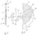
- the FIG. 1 shows a side view of a chipboard screw.
- the chipboard screw contains a screw body or screw shank 1, at one end 2 of which a screw head 3 is formed. It is a countersunk head.
- a screw head 3 In the flat end face 4 of the screw head 3 a not visible in the figure screw driving recess is arranged, with the aid of which the screw can be rotated.
- the screw body 1 forms at its, the screw head 3 remote from the front ends 6 a screw tip 5, which is a drill bit.
- the screw body 1 initially has a smooth shank portion 7, which is therefore designed to be thread-free.
- a milling section 8 in which a series of very steep ribs is arranged to facilitate screwing the screw into fibrous material.
- Such a milling section 8 can, as shown, be provided in a part-threaded screw, but also in a full-threaded screw.
- the threads of the thread 9 have a measured distance in the axial direction from each other, so that the outer contour 10 of the screw body 1 stops between the threads.
- the screw has a core diameter 11 and an outer diameter 12 of the thread, which is for example 50% larger than the core diameter 11.
- FIG. 2 shows a longitudinal section through the screw, the core 13 is shown on the right and the thread profile on the left.
- upwardly directed thread flank 14 is thus that thread flank which faces the screw head 3, while the lower thread flank 15 faces the front screw end 6 with the screw tip 5.
- the extending in this longitudinal section through the screw contour of the thread flank 14 is located on a circular arc with a radius 16. It goes into the outer contour 10 of the screw core 13 at an angle opposite, which is slightly larger than a right angle.
- the tangent 17 to the convexly curved upper thread flank 14 closes with the outer contour 10 of the screw at an angle 18 of just below 90 °.
- the contour of the front end of the screw 6 facing thread flank 15 is also located on a circular arc with a radius 19th
- a tangent 20 to the concave thread flank 15 at the point of transition into the outer contour 10 closes with this outer contour 10 an angle 21 a.
- This angle 21 is in a range of about 30 to 33 degrees.
- the curved thread flank 15 merges at an obtuse angle into the outer contour 10 of the screw, in the illustrated embodiment the angle is 147 to 150 degrees.
- the radius 16 of the curvature of the contour of the convexly curved thread flank 14 is in the illustrated embodiment at a value of about 92% of the core diameter 11 or at a value of about 61% of the outer diameter 12 of the thread of the screw.
- the radius of curvature 19 of the contour of the concave thread flank 15 is at a value of about 35% of the core diameter 11 or at a value of about 23% of the outer diameter 12 of the thread of the screw.
- the two thread flanks 14, 15 meet to form a thread edge 22.
- the tangent 23 to the screw head facing the thread flank 14 and the tangent 24 to the front end of the screw 6 facing thread flank 15 form at the thread edge an angle 25, which is approximately at 25 ° lies.
- a narrow flattening surface may also be provided, so that the thread edge 22 is then replaced by two side edges running parallel to the thread edge 22 and the narrow flattening surface extending therebetween.
- FIG. 3 shows a further embodiment according to the invention of a screw 30, which is approximately identical to the screw of Fig. 1 and 2 is constructed so that only the in Fig. 4 identifiable differences are explained below.
- the Fig. 4 shows a sectional view of the detail A of Fig. 3 ,
- the convex thread flank 14 and the concave thread flank 15 do not meet in a common thread edge 22, as in the screw according to FIG Fig. 1 and Fig. 2 but the thread flanks 14, 15 terminate at a common flattening surface 30 which is approximately parallel runs to the central longitudinal axis of the screw.
- the flattening surface 30 may be provided for production reasons.
- the screw drive end facing the convex thread flank 14 thus ends at an edge 31, which forms a side edge of the flattening surface 30 at the same time.
- the screw tip facing concave thread flank 15 terminates at an edge 32, which simultaneously forms another side edge of the flattening surface 30.
- edges 31, 32 run parallel to one another and enclose the flattening surface 30 between them.
- the flattening surface 30 and its side edges 31, 32 are parallel to an imaginary thread edge 33 which extends radially outside the flattening surface 30 and in which the tangents 23, 24 meet the thread flanks 14, 15 in their respective edges 31, 32.
- the tangents 23, 24 meet at an angle of 20 to 25 degrees, in the embodiment of the Fig. 4 at an angle of about 21 °.
- An angle 34, the tangent to the screw tip facing the concave thread flank 15 applied tangent 24 includes a running through the imaginary thread edge 33 perpendicular to the central longitudinal axis of the screw longitudinal axis is in the illustrated embodiment about 7 °.
- a height H of the flattening surface 30 is about 0.2 mm in the illustrated embodiment.
Description
Die Erfindung betrifft eine Schraube mit einem Schraubenschaft, der sich von einem Schraubenantriebsende, das beispielsweise einen Schraubenkopf aufweist, zu einer Schraubenspitze erstreckt, und der ein Gewinde aufweist.The invention relates to a screw with a screw shaft which extends from a screw drive end, which has for example a screw head, to a screw tip, and which has a thread.
Bei den herkömmlichen Gewinden verlaufen üblicherweise beide Gewindeflanken in einem Längsschnitt durch die Schraube geradlinig. Die Seitenkontur des Schraubenkerns zwischen den Gewindeflanken ist in den meisten Fällen geradlinig und parallel zu der Längsachse der Schraube.In the conventional threads usually both thread flanks are straight in a longitudinal section through the screw. The side contour of the screw core between the thread flanks is in most cases rectilinear and parallel to the longitudinal axis of the screw.
Es gibt symmetrische und unsymmetrische Gewinde. Bei den symmetrischen Gewinden ist der Winkel zwischen der dem Schraubenantriebsende zugewandten Gewindeflanke und der Längsachse der Schraube absolut genommen gleich groß wie der Winkel zwischen der Schraubenlängsachse und der gegenüberliegenden Gewindeflanke.There are symmetrical and asymmetrical threads. In the case of the symmetrical threads, the angle between the thread flank facing the screw drive end and the longitudinal axis of the screw is taken absolutely the same as the angle between the screw longitudinal axis and the opposite thread flank.
Bei unsymmetrischen Gewinden ist die dem Schraubenantriebsende zugewandte Gewindeflanke näher an einer Querebene zur Längsachse der Schraube als die gegenüberliegende Gewindeflanke.In asymmetrical threads, the screw drive end facing the thread flank is closer to a transverse plane to the longitudinal axis of the screw than the opposite thread flank.
Ebenfalls bekannt ist es, den Übergang zwischen der Gewindeflanke und dem Schaft mit einem sehr kleinen Radius abzurunden, um keine scharfe Kante entstehen zu lassen.It is also known to round off the transition between the thread flank and the shank with a very small radius so as not to create a sharp edge.
Weiterhin bekannt ist es, den Gewindegrund insgesamt abzurunden, wobei auch in diesen Fällen die Gewindeflanke über ihren größten Teil im Längsschnitt durch die Schraube geradlinig verläuft.It is also known to round off the thread base as a whole, in which case the thread flank extends in a straight line over its largest part in longitudinal section through the screw.
Es ist bereits eine gewindeformende Schraube zur Verwendung in weichem Material bekannt, bei der die dem Schraubenantriebsende abgewandte Gewindeflanke teilweise konkav ausgebildet ist und abgerundet in die gegenüberliegende Gewindeflanke übergeht (
Es ist bereits eine Schraube für Holz bekannt, bei der die dem Schraubenantriebsende zugewandte Flanke des Gewindes konvex und die gegenüberliegende Flanke des Gewindes konkav gekrümmt ist. Diese Schraube hat mindestens über die Hälfte der Länge des Schraubenschafts einen von der Spitze ausgehenden konischen Verlauf (
Der Erfindung liegt die Aufgabe zu Grunde, eine Schraube mit einer höheren Gewindestabilität und einem verringerten Einschraubmoment zu schaffen. Es soll sich dabei um eine Spanplattenschraube oder eine Schraube handeln, die auch in Kunststoff, Metall, Vollholz und anderen Materialien verwendet werden kann.The invention is based on the object to provide a screw with a higher thread stability and a reduced screw-in. It should be a chipboard screw or a screw, which can also be used in plastic, metal, solid wood and other materials.
Zur Lösung dieser Aufgabe schlägt die Erfindung eine Schraube mit den im Anspruch 1 genannten Merkmalen vor. Weiterbildungen der Erfindung sind Gegenstand von Unteransprüchen.To solve this problem, the invention proposes a screw with the features mentioned in
Die Gewindeflanken verlaufen im Schnitt erfindungsgemäß gebogen bzw. gekrümmt, und zwar die dem Schraubenantriebsende zugewandte Gewindeflanke konvex gekrümmt, und die gegenüberliegende dem vorderen Schraubenende zugewandte Gewindeflanke konkav gekrümmt.According to the invention, the thread flanks are curved or curved in section, specifically the thread flank facing the screw drive end convexly curved, and the opposite thread flank facing the front screw end concavely curved.
In Weiterbildung der Erfindung ist vorgesehen, dass die dem Schraubenantriebsende zugewandte Gewindeflanke beim Übergang in den Schraubenschaft im Wesentlichen rechtwinklig in diesen übergeht, allenfalls geringfügig oberhalb eines rechten Winkels, um das Herstellen des Gewindes mithilfe von Walzbacken zu ermöglichen.In a further development of the invention, it is provided that the thread flank facing the screw drive end merges into the screw shank substantially at right angles to the transition into the screw shank, at most slightly above a right angle to allow the manufacture of the thread by means of rolling dies.
In weiterer Ausgestaltung der Erfindung kann vorgesehen sein, dass die dem vorderen Schraubenende zugewandte Gewindeflanke schräg in den Schraubenschaft übergeht, so dass der Winkel zwischen der Gewindeflanke und der Außenkontur des Gewindeschafts einen stumpfen Winkel bildet, der beispielsweise in einem Bereich von 130 bis 160 Winkelgraden liegt.In a further embodiment of the invention can be provided that the front end of the screw facing flank merges obliquely into the screw shaft, so that the angle between the thread flank and the outer contour of the threaded shaft forms an obtuse angle, which is for example in a range of 130 to 160 degrees ,
Die beiden Gewindeflanken treffen sich in der Gewindekante, wobei an Stelle einer scharfen Gewindekante eine Abplattungsfläche vorgesehen sein kann, wobei die Tangenten an die jeweilige Gewindeflanke dann einen spitzen Winkel bilden, der beispielsweise im Bereich von 20 bis 30 Winkelgrad liegt, vorzugsweise bei einem Winkel von etwa 25 Winkelgrad.The two thread flanks meet in the thread edge, wherein instead of a sharp thread edge a flattening surface may be provided, the tangents to the respective thread flank then form an acute angle, which is for example in the range of 20 to 30 degrees, preferably at an angle of about 25 angular degrees.
Die Wölbung der Gewindeflanken kann einer beliebigen Kurve entsprechen. Es hat sich jedoch als besonders vorteilhaft herausgestellt, wenn die Wölbung der dem Schraubenantriebsende zugewandten Gewindeflanke und/oder die Wölbung der dem vorderen Schraubenende zugewandten Gewindeflanke einem Kreisbogen entspricht, also einer Krümmung mit einem konstanten Radius. Alternativ verlaufen die Gewindeflanken entlang einer Parabel, allgemein entlang einer Kurve oder entlang einer Aneinanderreihung gerader Strecken, die in eine Wölbung eingepasst sind.The curvature of the thread flanks can correspond to any curve. However, it has proved to be particularly advantageous if the curvature of the screw drive end facing the thread flank and / or the curvature of the front end of the screw facing the thread flank corresponds to a circular arc, ie a curvature with a constant radius. Alternatively, the thread flanks extend along a parabola, generally along a curve or along a string of straight stretches fitted into a camber.
In weiterer Ausgestaltung der Erfindung liegt der Krümmungsradius der konkav gebogenen Gewindeflanke in einem Bereich zwischen 30% und 50%, insbesondere 36% und 46%, des Kerndurchmessers der Schraube.In a further embodiment of the invention, the radius of curvature of the concave curved thread flank is in a range between 30% and 50%, in particular 36% and 46%, of the core diameter of the screw.
Es ist ebenfalls möglich, dass dieser Krümmungsradius der konkaven Gewindeflanke in einem Bereich zwischen 20% und 30%, insbesondere 23% und 28%, des Außendurchmessers des Gewindes der Schraube liegt.It is also possible that this radius of curvature of the concave thread flank is in a range between 20% and 30%, in particular 23% and 28%, of the outer diameter of the thread of the screw.
Erfindungsgemäß kann vorgesehen sein, dass der Krümmungsradius der konvex gekrümmten Gewindeflanke in einem Bereich zwischen 90% und 170%, insbesondere 130% und 165% oder 90% und 95%, des Kerndurchmessers der Schraube.According to the invention it can be provided that the radius of curvature of the convexly curved thread flank in a range between 90% and 170%, in particular 130% and 165% or 90% and 95%, of the core diameter of the screw.
Es kann nach einem weiteren Merkmal der Erfindung vorgesehen sein, dass der Krümmungsradius der konvex gekrümmten Gewindeflanke im Bereich von 60% bis 100%, insbesondere 60% bis 63% oder 80% bis 100%, des Außendurchmessers des Gewindes der Schraube liegt.It may be provided according to a further feature of the invention that the radius of curvature of the convexly curved thread flank is in the range of 60% to 100%, in particular 60% to 63% or 80% to 100%, of the outer diameter of the thread of the screw.
In weiterer Ausgestaltung der Erfindung kann vorgesehen sein, dass das Verhältnis des Außendurchmessers des Gewindes der Schraube zu dem Kerndurchmesser der Schraube bei etwa 1,5, insbesondere zwischen 1,45 und 1,7, liegt.In a further embodiment of the invention can be provided that the ratio of the outer diameter of the thread of the screw to the core diameter of the screw at about 1.5, in particular between 1.45 and 1.7, is located.
Weitere Merkmale, Einzelheiten und Vorzüge der Erfindung ergeben sich aus den Ansprüchen und der Zusammenfassung, deren beider Wortlaut durch Bezugnahme zum Inhalt der Beschreibung gemacht wird, der folgenden Beschreibung bevorzugter Ausführungsformen der Erfindung sowie anhand der Zeichnung. Einzelmerkmale der unterschiedlichen Ausführungsformen lassen sich dabei in beliebiger Weise kombinieren.Further features, details and advantages of the invention will become apparent from the claims and the abstract, the wording of which is incorporated by reference into the content of the description, the following description of preferred embodiments of the invention and with reference to the drawing. Individual features of the different embodiments can be combined in any way.
Hierbei zeigen:
Figur 1- eine Seitenansicht einer von der Erfindung vorgeschlagenen, als Spanplattenschraube ausgebildeten Schraube gemäß einer ersten Ausführungsform;
Figur 2- einen stark vergrößerten Ausschnitt A aus der
Figur 1 Figur 3- eine Seitenansicht eines von der Erfindung vorgeschlagenen als Spanplattenschraube ausgebildeten Schraube gemäß einer zweiten Ausführungsform;
Figur 4- einen stark vergrößerten Ausschnitt A aus der
Figur 3
- FIG. 1
- a side view of a proposed by the invention, designed as a chipboard screw screw according to a first embodiment;
- FIG. 2
- a greatly enlarged section A from the
FIG. 1 with a longitudinal section of the screw; - FIG. 3
- a side view of a proposed by the invention designed as chipboard screw screw according to a second embodiment;
- FIG. 4
- a greatly enlarged section A from the
FIG. 3 with a longitudinal section of the screw.
Die
Von dem Schraubenkopf 3 ausgehend weist der Schraubenkörper 1 zunächst einen glatten Schaftabschnitt 7 auf, der also gewindefrei ausgebildet ist. Daran schließt sich ein Fräsabschnitt 8 an, bei dem eine Reihe von sehr steil verlaufenden Rippen angeordnet ist, die das Einschrauben der Schraube in faseriges Material erleichtern sollen. Ein solcher Fräsabschnitt 8 kann, wie dargestellt, bei einer Teilgewindeschraube, aber auch bei einer Vollgewindeschraube vorgesehen sein.Starting from the
Über den restlichen Teil des Schraubenkörpers erstreckt sich ein Gewinde 9, das bis zu der Schraubenspitze 5 reicht. Die Gewindegänge des Gewindes 9 haben einen in axialer Richtung gemessenen Abstand voneinander, so dass zwischen den Gewindegängen die Außenkontur 10 des Schraubenkörpers 1 stehen bleibt.About the remaining part of the screw body extends a
Die Schraube hat einen Kerndurchmesser 11 und einen Außendurchmesser 12 des Gewindes, der beispielsweise um 50% größer ist als der Kerndurchmesser 11.The screw has a
Die Profilform des Gewindes ist in der
Die in diesem Längsschnitt durch die Schraube verlaufende Kontur der Gewindeflanke 14 liegt auf einem Kreisbogen mit einem Radius 16. Sie geht in die Außenkontur 10 des Schraubenkerns 13 in einem Winkel gegenüber, der etwas größer ist als ein rechter Winkel. Die Tangente 17 an die konvex gekrümmte obere Gewindeflanke 14 schließt mit der Außenkontur 10 der Schraube einen Winkel 18 von knapp unter 90° ein.The extending in this longitudinal section through the screw contour of the
Die Kontur der dem vorderen Schraubenende 6 zugewandten Gewindeflanke 15 liegt ebenfalls auf einem Kreisbogen mit einem Radius 19.The contour of the front end of the
Eine Tangente 20 an die konkav gekrümmte Gewindeflanke 15 an der Stelle des Übergangs in die Außenkontur 10 schließt mit dieser Außenkontur 10 einen Winkel 21 ein. Dieser Winkel 21 liegt in einem Bereich von etwa 30 bis 33 Winkelgrad.A tangent 20 to the
Dadurch geht die gekrümmte Gewindeflanke 15 in einem stumpfen Winkel in die Außenkontur 10 der Schraube über, bei der dargestellten Ausführungsform beträgt der Winkel 147 bis 150 Winkelgrad.As a result, the
Der Radius 16 der Krümmung der Kontur der konvex gekrümmten Gewindeflanke 14 liegt bei der dargestellten Ausführungsform bei einem Wert von etwa 92% des Kerndurchmessers 11 oder bei einem Wert von etwa 61% des Außendurchmessers 12 des Gewindes der Schraube.The
Der Krümmungsradius 19 der Kontur der konkav gekrümmten Gewindeflanke 15 liegt bei einem Wert von etwa 35% des Kerndurchmessers 11 bzw. bei einem Wert von etwa 23% des Außendurchmessers 12 des Gewindes der Schraube.The radius of
Die beiden Gewindeflanken 14, 15 treffen sich zur Bildung einer Gewindekante 22. Die Tangente 23 an die dem Schraubenkopf zugewandte Gewindeflanke 14 und die Tangente 24 an die dem vorderen Schraubenende 6 zugewandte Gewindeflanke 15 bilden an der Gewindekante einen Winkel 25, der etwa bei 25° liegt. Aus produktionstechnischen Gründen kann an Stelle der Gewindekante 22 auch eine schmale Abplattungsfläche vorgesehen sein, so dass die Gewindekante 22 dann durch zwei parallel zur Gewindekante 22 verlaufende Seitenkanten und die dazwischen verlaufende schmale Abplattungsfläche ersetzt ist.The two
Die
Die
Ein Winkel 34, den die Tangente an die der Schraubenspitze zugewandte konkave Gewindeflanke 15 angelegte Tangente 24 mit einer durch die gedachte Gewindekante 33 verlaufenden Senkrechten auf die Mittellängsachse der Schraubenlängsachse einschließt beträgt bei der dargestellten Ausführungsform etwa 7°.An
Eine Höhe H der Abplattungsfläche 30 beträgt bei der dargestellten Ausführungsform etwa 0,2 mm.A height H of the flattening
Claims (6)
- Screw, comprising- an essentially cylindrical screw body (1) which- extends from a screw drive end (2) up to a front screw end (6), and comprising- a screw thread (9) extending at least over part of the screw body (1) up to the front screw end (6),- with a thread flank (14) thereof facing towards the screw drive end (2) having a convex curvature, and- with a thread flank (15) thereof facing away from the screw drive end (2) having a concave curvature,characterized in that- the thread flank (14) facing towards the screw drive end (2) merges into the screw shank (13) approximately at right angles or, as an alternative, at an angle between 85 degrees of angle and 90 degrees of angle, and- both the thread flanks (14, 15) meet on the thread edge (22) at an angle (25) of 20 degrees of angle to 25 degrees of angle, in particular 25 degrees of angle, or- end on a flattening surface (30) and tangents (23, 24) on the two thread flanks (14, 15) meet on an imaginary thread edge (33) radially outside the flattening surface (30) at an angle between 20 degrees of angle and 25 degrees of angle, in particular 21 degrees of angle.
- Screw according to claim 1, wherein the thread flank (15) facing away from the screw drive end (2) merges into the screw shank (13) at an obtuse angle.
- Screw according to any of the preceding claims, wherein the curvature of the thread flank (14) facing towards the screw drive end (2) and/or of the thread flank (15) facing away from the screw drive end (2) corresponds to a circular arc, a parabola or a sequence of straight lines following a bent curve.
- Screw according to any of the preceding claims, wherein the radius of curvature (19) of the thread flank (15) facing towards the front screw end (6) is between 30% and 50%, in particular 36% and 46%, of the core diameter (11) of the screw and/or between 20% and 30%, in particular 23% and 28%, of the outer diameter (12) of the thread (9) of the screw.
- Screw according to any of the preceding claims, wherein the radius of curvature (16) of the thread flank (14) facing towards the screw drive end (2) is between 90% and 170%, in particular 130% and 165%, or 90% and 95%, of the core diameter (11) and/or between 60% and 100%, in particular 60% to 63%, or 90% to 100%, of the outer diameter (12) of the thread (9) of the screw.
- Screw according to any of the preceding claims, wherein the ratio of outer diameter (12) of the thread (9) to core diameter of the screw is approximately 1.5, in particular between 1.45 and 1.7.
Applications Claiming Priority (1)
| Application Number | Priority Date | Filing Date | Title |
|---|---|---|---|
| DE201310210566 DE102013210566A1 (en) | 2013-06-06 | 2013-06-06 | screw |
Publications (2)
| Publication Number | Publication Date |
|---|---|
| EP2811181A1 EP2811181A1 (en) | 2014-12-10 |
| EP2811181B1 true EP2811181B1 (en) | 2017-07-05 |
Family
ID=50687414
Family Applications (1)
| Application Number | Title | Priority Date | Filing Date |
|---|---|---|---|
| EP14168304.5A Active EP2811181B1 (en) | 2013-06-06 | 2014-05-14 | Screw |
Country Status (2)
| Country | Link |
|---|---|
| EP (1) | EP2811181B1 (en) |
| DE (1) | DE102013210566A1 (en) |
Families Citing this family (1)
| Publication number | Priority date | Publication date | Assignee | Title |
|---|---|---|---|---|
| DE102021126035A1 (en) | 2021-10-07 | 2023-04-13 | MFI-Metall Fastening Industrie GmbH | wood screw |
Family Cites Families (7)
| Publication number | Priority date | Publication date | Assignee | Title |
|---|---|---|---|---|
| US1336773A (en) * | 1916-12-14 | 1920-04-13 | Caldweil John William | Screw |
| US3459250A (en) * | 1967-04-14 | 1969-08-05 | Burdsall Russell & Ward Bolt & | Prevailing-torque lockscrews |
| US3523565A (en) * | 1968-04-29 | 1970-08-11 | Allied Prod Corp | Self locking male threaded fastener |
| DE2157373A1 (en) * | 1970-11-23 | 1972-05-25 | Textron Inc | Self-retaining fastener and tool for its manufacture |
| DE8103990U1 (en) * | 1981-02-13 | 1982-09-30 | Jaeger Eberhard Gmbh & Co Kg, 5928 Laasphe | Self-tapping screw |
| WO2006043169A1 (en) * | 2004-10-22 | 2006-04-27 | Ajax Cooke Pty Ltd | Screw and fastening system for profiled sheeting |
| BRPI0815194B1 (en) * | 2007-08-13 | 2019-07-02 | Research Engineering & Manufacturing, Inc. | THREAD FORMER |
-
2013
- 2013-06-06 DE DE201310210566 patent/DE102013210566A1/en not_active Withdrawn
-
2014
- 2014-05-14 EP EP14168304.5A patent/EP2811181B1/en active Active
Also Published As
| Publication number | Publication date |
|---|---|
| EP2811181A1 (en) | 2014-12-10 |
| DE102013210566A1 (en) | 2014-12-11 |
Similar Documents
| Publication | Publication Date | Title |
|---|---|---|
| EP0869287B1 (en) | Self-piercing and self-threading fastening element | |
| DE4333791C2 (en) | Tapping screw | |
| EP1568901B1 (en) | Thread-forming screw | |
| EP1718876B1 (en) | Thread-forming screw | |
| WO2010003901A1 (en) | Screw | |
| DE102010000702A1 (en) | Thread forming screw and its use | |
| EP2012026A2 (en) | Screw | |
| EP2806174A1 (en) | Screw element | |
| AT412665B (en) | SCREW FOR USE ON PARTS MANUFACTURED FROM WOOD | |
| DE102014000940A1 (en) | Screw, mounting arrangement and use of a screw | |
| EP3377777B1 (en) | Thread-forming or self-tapping screw, in particular for use in light metal | |
| DE19525732A1 (en) | Screw with head, threaded stem, and tip section - which contains milling ribs, forming milling edge protruding above tip surface | |
| DE19632838A1 (en) | Screw with a self-drilling tip | |
| EP0504782B1 (en) | Screw, method and rolling die for manufacturing the same | |
| EP2811181B1 (en) | Screw | |
| EP3374649B1 (en) | Thread-forming screw | |
| EP2150709B1 (en) | Particle board screw | |
| EP3655669B1 (en) | Wood screw | |
| EP3426937B1 (en) | Screw | |
| DE19541839A1 (en) | Self-tapping screw for use in chipboard | |
| DE3046692C2 (en) | Thread rolling screw | |
| EP3542076B1 (en) | Wood screw and method for producing a wood screw | |
| EP1873405A2 (en) | Chipboard screw | |
| DE3923091A1 (en) | Countersunk screw | |
| DE102017002069A1 (en) | Screw-in dowel and fastening system with a screw-in dowel |
Legal Events
| Date | Code | Title | Description |
|---|---|---|---|
| PUAI | Public reference made under article 153(3) epc to a published international application that has entered the european phase |
Free format text: ORIGINAL CODE: 0009012 |
|
| 17P | Request for examination filed |
Effective date: 20140514 |
|
| AK | Designated contracting states |
Kind code of ref document: A1 Designated state(s): AL AT BE BG CH CY CZ DE DK EE ES FI FR GB GR HR HU IE IS IT LI LT LU LV MC MK MT NL NO PL PT RO RS SE SI SK SM TR |
|
| AX | Request for extension of the european patent |
Extension state: BA ME |
|
| R17P | Request for examination filed (corrected) |
Effective date: 20141223 |
|
| RBV | Designated contracting states (corrected) |
Designated state(s): AL AT BE BG CH CY CZ DE DK EE ES FI FR GB GR HR HU IE IS IT LI LT LU LV MC MK MT NL NO PL PT RO RS SE SI SK SM TR |
|
| GRAP | Despatch of communication of intention to grant a patent |
Free format text: ORIGINAL CODE: EPIDOSNIGR1 |
|
| INTG | Intention to grant announced |
Effective date: 20170105 |
|
| GRAS | Grant fee paid |
Free format text: ORIGINAL CODE: EPIDOSNIGR3 |
|
| GRAA | (expected) grant |
Free format text: ORIGINAL CODE: 0009210 |
|
| AK | Designated contracting states |
Kind code of ref document: B1 Designated state(s): AL AT BE BG CH CY CZ DE DK EE ES FI FR GB GR HR HU IE IS IT LI LT LU LV MC MK MT NL NO PL PT RO RS SE SI SK SM TR |
|
| REG | Reference to a national code |
Ref country code: GB Ref legal event code: FG4D Free format text: NOT ENGLISH |
|
| REG | Reference to a national code |
Ref country code: CH Ref legal event code: EP Ref country code: CH Ref legal event code: NV Representative=s name: DR. LUSUARDI AG, CH |
|
| REG | Reference to a national code |
Ref country code: AT Ref legal event code: REF Ref document number: 906814 Country of ref document: AT Kind code of ref document: T Effective date: 20170715 |
|
| REG | Reference to a national code |
Ref country code: IE Ref legal event code: FG4D Free format text: LANGUAGE OF EP DOCUMENT: GERMAN |
|
| REG | Reference to a national code |
Ref country code: DE Ref legal event code: R096 Ref document number: 502014004465 Country of ref document: DE |
|
| REG | Reference to a national code |
Ref country code: NL Ref legal event code: MP Effective date: 20170705 |
|
| REG | Reference to a national code |
Ref country code: LT Ref legal event code: MG4D |
|
| PG25 | Lapsed in a contracting state [announced via postgrant information from national office to epo] |
Ref country code: HR Free format text: LAPSE BECAUSE OF FAILURE TO SUBMIT A TRANSLATION OF THE DESCRIPTION OR TO PAY THE FEE WITHIN THE PRESCRIBED TIME-LIMIT Effective date: 20170705 Ref country code: NL Free format text: LAPSE BECAUSE OF FAILURE TO SUBMIT A TRANSLATION OF THE DESCRIPTION OR TO PAY THE FEE WITHIN THE PRESCRIBED TIME-LIMIT Effective date: 20170705 Ref country code: NO Free format text: LAPSE BECAUSE OF FAILURE TO SUBMIT A TRANSLATION OF THE DESCRIPTION OR TO PAY THE FEE WITHIN THE PRESCRIBED TIME-LIMIT Effective date: 20171005 Ref country code: LT Free format text: LAPSE BECAUSE OF FAILURE TO SUBMIT A TRANSLATION OF THE DESCRIPTION OR TO PAY THE FEE WITHIN THE PRESCRIBED TIME-LIMIT Effective date: 20170705 Ref country code: FI Free format text: LAPSE BECAUSE OF FAILURE TO SUBMIT A TRANSLATION OF THE DESCRIPTION OR TO PAY THE FEE WITHIN THE PRESCRIBED TIME-LIMIT Effective date: 20170705 Ref country code: SE Free format text: LAPSE BECAUSE OF FAILURE TO SUBMIT A TRANSLATION OF THE DESCRIPTION OR TO PAY THE FEE WITHIN THE PRESCRIBED TIME-LIMIT Effective date: 20170705 |
|
| PG25 | Lapsed in a contracting state [announced via postgrant information from national office to epo] |
Ref country code: RS Free format text: LAPSE BECAUSE OF FAILURE TO SUBMIT A TRANSLATION OF THE DESCRIPTION OR TO PAY THE FEE WITHIN THE PRESCRIBED TIME-LIMIT Effective date: 20170705 Ref country code: LV Free format text: LAPSE BECAUSE OF FAILURE TO SUBMIT A TRANSLATION OF THE DESCRIPTION OR TO PAY THE FEE WITHIN THE PRESCRIBED TIME-LIMIT Effective date: 20170705 Ref country code: GR Free format text: LAPSE BECAUSE OF FAILURE TO SUBMIT A TRANSLATION OF THE DESCRIPTION OR TO PAY THE FEE WITHIN THE PRESCRIBED TIME-LIMIT Effective date: 20171006 Ref country code: BG Free format text: LAPSE BECAUSE OF FAILURE TO SUBMIT A TRANSLATION OF THE DESCRIPTION OR TO PAY THE FEE WITHIN THE PRESCRIBED TIME-LIMIT Effective date: 20171005 Ref country code: ES Free format text: LAPSE BECAUSE OF FAILURE TO SUBMIT A TRANSLATION OF THE DESCRIPTION OR TO PAY THE FEE WITHIN THE PRESCRIBED TIME-LIMIT Effective date: 20170705 Ref country code: PL Free format text: LAPSE BECAUSE OF FAILURE TO SUBMIT A TRANSLATION OF THE DESCRIPTION OR TO PAY THE FEE WITHIN THE PRESCRIBED TIME-LIMIT Effective date: 20170705 Ref country code: IS Free format text: LAPSE BECAUSE OF FAILURE TO SUBMIT A TRANSLATION OF THE DESCRIPTION OR TO PAY THE FEE WITHIN THE PRESCRIBED TIME-LIMIT Effective date: 20171105 |
|
| REG | Reference to a national code |
Ref country code: DE Ref legal event code: R097 Ref document number: 502014004465 Country of ref document: DE |
|
| PG25 | Lapsed in a contracting state [announced via postgrant information from national office to epo] |
Ref country code: RO Free format text: LAPSE BECAUSE OF FAILURE TO SUBMIT A TRANSLATION OF THE DESCRIPTION OR TO PAY THE FEE WITHIN THE PRESCRIBED TIME-LIMIT Effective date: 20170705 Ref country code: DK Free format text: LAPSE BECAUSE OF FAILURE TO SUBMIT A TRANSLATION OF THE DESCRIPTION OR TO PAY THE FEE WITHIN THE PRESCRIBED TIME-LIMIT Effective date: 20170705 Ref country code: CZ Free format text: LAPSE BECAUSE OF FAILURE TO SUBMIT A TRANSLATION OF THE DESCRIPTION OR TO PAY THE FEE WITHIN THE PRESCRIBED TIME-LIMIT Effective date: 20170705 |
|
| PLBE | No opposition filed within time limit |
Free format text: ORIGINAL CODE: 0009261 |
|
| STAA | Information on the status of an ep patent application or granted ep patent |
Free format text: STATUS: NO OPPOSITION FILED WITHIN TIME LIMIT |
|
| REG | Reference to a national code |
Ref country code: FR Ref legal event code: PLFP Year of fee payment: 5 |
|
| PG25 | Lapsed in a contracting state [announced via postgrant information from national office to epo] |
Ref country code: EE Free format text: LAPSE BECAUSE OF FAILURE TO SUBMIT A TRANSLATION OF THE DESCRIPTION OR TO PAY THE FEE WITHIN THE PRESCRIBED TIME-LIMIT Effective date: 20170705 Ref country code: SM Free format text: LAPSE BECAUSE OF FAILURE TO SUBMIT A TRANSLATION OF THE DESCRIPTION OR TO PAY THE FEE WITHIN THE PRESCRIBED TIME-LIMIT Effective date: 20170705 Ref country code: SK Free format text: LAPSE BECAUSE OF FAILURE TO SUBMIT A TRANSLATION OF THE DESCRIPTION OR TO PAY THE FEE WITHIN THE PRESCRIBED TIME-LIMIT Effective date: 20170705 Ref country code: IT Free format text: LAPSE BECAUSE OF FAILURE TO SUBMIT A TRANSLATION OF THE DESCRIPTION OR TO PAY THE FEE WITHIN THE PRESCRIBED TIME-LIMIT Effective date: 20170705 |
|
| 26N | No opposition filed |
Effective date: 20180406 |
|
| PG25 | Lapsed in a contracting state [announced via postgrant information from national office to epo] |
Ref country code: SI Free format text: LAPSE BECAUSE OF FAILURE TO SUBMIT A TRANSLATION OF THE DESCRIPTION OR TO PAY THE FEE WITHIN THE PRESCRIBED TIME-LIMIT Effective date: 20170705 |
|
| PG25 | Lapsed in a contracting state [announced via postgrant information from national office to epo] |
Ref country code: MT Free format text: LAPSE BECAUSE OF FAILURE TO SUBMIT A TRANSLATION OF THE DESCRIPTION OR TO PAY THE FEE WITHIN THE PRESCRIBED TIME-LIMIT Effective date: 20170705 |
|
| GBPC | Gb: european patent ceased through non-payment of renewal fee |
Effective date: 20180514 |
|
| REG | Reference to a national code |
Ref country code: BE Ref legal event code: MM Effective date: 20180531 |
|
| PG25 | Lapsed in a contracting state [announced via postgrant information from national office to epo] |
Ref country code: MC Free format text: LAPSE BECAUSE OF FAILURE TO SUBMIT A TRANSLATION OF THE DESCRIPTION OR TO PAY THE FEE WITHIN THE PRESCRIBED TIME-LIMIT Effective date: 20170705 |
|
| REG | Reference to a national code |
Ref country code: IE Ref legal event code: MM4A |
|
| PG25 | Lapsed in a contracting state [announced via postgrant information from national office to epo] |
Ref country code: LU Free format text: LAPSE BECAUSE OF NON-PAYMENT OF DUE FEES Effective date: 20180514 |
|
| PG25 | Lapsed in a contracting state [announced via postgrant information from national office to epo] |
Ref country code: IE Free format text: LAPSE BECAUSE OF NON-PAYMENT OF DUE FEES Effective date: 20180514 Ref country code: GB Free format text: LAPSE BECAUSE OF NON-PAYMENT OF DUE FEES Effective date: 20180514 |
|
| PG25 | Lapsed in a contracting state [announced via postgrant information from national office to epo] |
Ref country code: BE Free format text: LAPSE BECAUSE OF NON-PAYMENT OF DUE FEES Effective date: 20180531 |
|
| PG25 | Lapsed in a contracting state [announced via postgrant information from national office to epo] |
Ref country code: TR Free format text: LAPSE BECAUSE OF FAILURE TO SUBMIT A TRANSLATION OF THE DESCRIPTION OR TO PAY THE FEE WITHIN THE PRESCRIBED TIME-LIMIT Effective date: 20170705 |
|
| PG25 | Lapsed in a contracting state [announced via postgrant information from national office to epo] |
Ref country code: HU Free format text: LAPSE BECAUSE OF FAILURE TO SUBMIT A TRANSLATION OF THE DESCRIPTION OR TO PAY THE FEE WITHIN THE PRESCRIBED TIME-LIMIT; INVALID AB INITIO Effective date: 20140514 Ref country code: PT Free format text: LAPSE BECAUSE OF FAILURE TO SUBMIT A TRANSLATION OF THE DESCRIPTION OR TO PAY THE FEE WITHIN THE PRESCRIBED TIME-LIMIT Effective date: 20170705 |
|
| PG25 | Lapsed in a contracting state [announced via postgrant information from national office to epo] |
Ref country code: MK Free format text: LAPSE BECAUSE OF NON-PAYMENT OF DUE FEES Effective date: 20170705 Ref country code: CY Free format text: LAPSE BECAUSE OF FAILURE TO SUBMIT A TRANSLATION OF THE DESCRIPTION OR TO PAY THE FEE WITHIN THE PRESCRIBED TIME-LIMIT Effective date: 20170705 |
|
| PG25 | Lapsed in a contracting state [announced via postgrant information from national office to epo] |
Ref country code: AL Free format text: LAPSE BECAUSE OF FAILURE TO SUBMIT A TRANSLATION OF THE DESCRIPTION OR TO PAY THE FEE WITHIN THE PRESCRIBED TIME-LIMIT Effective date: 20170705 |
|
| PGFP | Annual fee paid to national office [announced via postgrant information from national office to epo] |
Ref country code: FR Payment date: 20230526 Year of fee payment: 10 Ref country code: DE Payment date: 20230519 Year of fee payment: 10 Ref country code: CH Payment date: 20230602 Year of fee payment: 10 |
|
| PGFP | Annual fee paid to national office [announced via postgrant information from national office to epo] |
Ref country code: AT Payment date: 20230522 Year of fee payment: 10 |