EP0508091B1 - Luftreifen mit verbesserter Entgasung - Google Patents
Luftreifen mit verbesserter Entgasung Download PDFInfo
- Publication number
- EP0508091B1 EP0508091B1 EP92103502A EP92103502A EP0508091B1 EP 0508091 B1 EP0508091 B1 EP 0508091B1 EP 92103502 A EP92103502 A EP 92103502A EP 92103502 A EP92103502 A EP 92103502A EP 0508091 B1 EP0508091 B1 EP 0508091B1
- Authority
- EP
- European Patent Office
- Prior art keywords
- tire
- sidewall
- tread
- shoulder
- grooves
- Prior art date
- Legal status (The legal status is an assumption and is not a legal conclusion. Google has not performed a legal analysis and makes no representation as to the accuracy of the status listed.)
- Expired - Lifetime
Links
- 238000013022 venting Methods 0.000 title description 7
- 239000011324 bead Substances 0.000 claims description 10
- 239000007789 gas Substances 0.000 claims description 7
- 238000004073 vulcanization Methods 0.000 claims description 4
- 230000000977 initiatory effect Effects 0.000 claims description 2
- 230000037361 pathway Effects 0.000 claims description 2
- 239000005060 rubber Substances 0.000 description 9
- 239000000463 material Substances 0.000 description 3
- XLYOFNOQVPJJNP-UHFFFAOYSA-N water Substances O XLYOFNOQVPJJNP-UHFFFAOYSA-N 0.000 description 3
- 241000254043 Melolonthinae Species 0.000 description 1
- 229910000831 Steel Inorganic materials 0.000 description 1
- 230000000295 complement effect Effects 0.000 description 1
- 230000032798 delamination Effects 0.000 description 1
- 230000001066 destructive effect Effects 0.000 description 1
- 238000006073 displacement reaction Methods 0.000 description 1
- 239000004744 fabric Substances 0.000 description 1
- 239000012530 fluid Substances 0.000 description 1
- 238000004519 manufacturing process Methods 0.000 description 1
- 210000000006 pectoral fin Anatomy 0.000 description 1
- 230000002787 reinforcement Effects 0.000 description 1
- 230000003014 reinforcing effect Effects 0.000 description 1
- 239000010959 steel Substances 0.000 description 1
- 239000000126 substance Substances 0.000 description 1
- 239000011800 void material Substances 0.000 description 1
Images


Classifications
-
- B—PERFORMING OPERATIONS; TRANSPORTING
- B60—VEHICLES IN GENERAL
- B60C—VEHICLE TYRES; TYRE INFLATION; TYRE CHANGING; CONNECTING VALVES TO INFLATABLE ELASTIC BODIES IN GENERAL; DEVICES OR ARRANGEMENTS RELATED TO TYRES
- B60C11/00—Tyre tread bands; Tread patterns; Anti-skid inserts
- B60C11/03—Tread patterns
- B60C11/0306—Patterns comprising block rows or discontinuous ribs
-
- B—PERFORMING OPERATIONS; TRANSPORTING
- B60—VEHICLES IN GENERAL
- B60C—VEHICLE TYRES; TYRE INFLATION; TYRE CHANGING; CONNECTING VALVES TO INFLATABLE ELASTIC BODIES IN GENERAL; DEVICES OR ARRANGEMENTS RELATED TO TYRES
- B60C13/00—Tyre sidewalls; Protecting, decorating, marking, or the like, thereof
- B60C13/02—Arrangement of grooves or ribs
Definitions
- the invention relates to a pneumatic tire in which the tread design and the sidewall design are integrated.
- the material used to make the tread and the materials used to make the sidewall are different because of the different physical requirements of these two parts of the tire.
- the tread rubber must be relatively stiff and wear resistant, and provide good traction.
- the sidewall must be relatively pliable and scuff and puncture resistant. Partially because of their different physical requirements, sidewalls are ordinarily made substantially smooth and the tread is made with a plurality of block traction elements or lugs.
- Tread designs where the lugs extend partially into the shoulder portion of the tire are for instance known from DE-C- 696 302 corresponding to the preamble of claim 1 or US-A- 3 818 965.
- Bead means that part of the tire comprising an annular tensile member wrapped by ply cords and shaped, with or without other reinforcement elements such as flippers, chippers, apexes, toe guards and chafers, to fit the design rim.
- Carcass means the tire structure apart from the belt structure, tread, undertread, and sidewall rubber over the plies, but including the beads.
- “Crown” refers to the circumferentially outermost portion of the carcass substantially within the width limits of the tread.
- “Groove” means an elongated void area in a tread that may extend circumferentially or laterally about the tread in a straight, curved, or zig-zag manner.
- Logarithmic spiral refers to a spiral that has a gradually expanding arc, as opposed to a substantially constant arc as in for example an Archemedic spiral (i.e. as seen in a phonograph record).
- “Lugs” refer to discontinuous radial rows of tread rubber in direct contact with the road surface.
- Net-to-gross refers to the ratio of the ground contacting surface of a tread to the total tread area.
- Peak refers to the distance from one peak in the tread pattern to the next.
- Pitch boundary refers to a substantially lateral line in the circumference of the tire that defines the beginning or end of the pitch.
- the pitch boundary may be defined by the center of a lateral groove.
- a pitch boundary “shift” refers to a circumferential displacement of the line.
- Pneumatic tire means a laminated mechanical device of generally toroidal shape (usually an open-torus) having beads and a tread and made of rubber, chemicals, fabric and steel or other materials. When mounted on the wheel of a motor vehicle, the tire through its tread provides traction and contains the fluid that sustains the vehicle load.
- Ring and radially are used to mean directions radially toward or away from the axis of rotation of the tire.
- Shader refers to the upper portion of sidewall just below the tread edge.
- “Sidewall” means that portion of a tire between the tread and the bead.
- Thread means a molded rubber component which, when bonded to a tire casing, includes that portion of the tire that comes into contact with the road when the tire is normally inflated and under normal load.
- a pneumatic tire comprising a pair of annular beads, carcass plies wrapped around the beads, a tread disposed over the carcass plies and sidewalls disposed between the tread and beads, the tire having a pattern created by lateral tread grooves in the shoulder area of the tire which is continued in the sidewall.
- lateral grooves in the tread extend well into the shoulder area in the proximity of the sidewall.
- the pattern in the sidewall comprises grooves or serrations which originate in the vicinity of the maximum section width of the tire and terminate in the vicinity of the tire shoulder.
- the sidewall grooves or serrations have an angle that substantially complements or matches the angle of the lateral grooves in the shoulder.
- a tire having a directional tread in which the lateral grooves have an angle in the shoulder of the tire of about 35°to 90° with respect to a line tangent to the tire, and has grooves or serrations in the sidewall having an angle of 45° to 90° relative to the tangent line.
- the serrations in the sidewall improve the venting of the tire during vulcanization since the sidewall grooves provide a channel for the escape of venting gases. Since the sidewall grooves substantially match up with the shoulder grooves or lateral grooves of the tread it is believed that venting is substantially less restricted. Also, the ridges of the sidewall make the sidewall more resistant to cracks, and possibly improve the impact resistance of the sidewall.
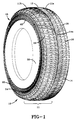
- Fig. 1 illustrates a perspective view of an illustrated embodiment of a tire incorporating the inventive concept described herein.
- Fig. 2 illustrates the sidewall of the illustrated tire.
- Fig. 2A is an enlarged segment of the tire sidewall.
- tire 10 has a tread 11 which has lateral grooves 14 which extend deep into shoulder 16 at an angle of about 35° to 90°, preferably 50° to 75° with respect to a line tangent to the tire.
- the shoulder grooves may be angled so that the trailing end 18 of the groove (in the shoulder) is the last part of the lateral groove 14 to leave the footprint when the tire is rotated in the forward direction of travel.
- Sidewall 20 has grooves or serrations 22 that are angled to substantially match the angle of the shoulder grooves.
- the angle of serrations 22 may be the same as, may be less than, or may be more than the angle of lateral grooves 14. In general, the angle of the sidewall serrations may be 45° to 90°, preferably 50° to 90° with respect to a line tangent to the tire.
- the angle of the serrations is 90°.
- tire 10 has a tread portion 11 which is divided into two parts, 11a, 11b by aqua channel 12.
- Curved lateral grooves 14 initiate in aqua channel 12 and take an uninterrupted arcuate path to shoulder 16.
- Circumferential grooves 26 intersect lateral grooves 14 forming lugs 28.
- the curvature of the lateral grooves of tire 10 is such that the center or initial portion 14a of a lateral groove is in the leading edge of the footprint initiating the flow of water before the rest of the lateral groove enters the footprint, and as the main portion of the lateral groove enters the footprint, water in lateral groove 14 is expelled through the shoulder area with great force.
- the tread of the tire is directional since, if the tire is mounted such that the center portion 14a of the lateral groove enters the footprint last, water would be channeled toward, instead of away from the aqua-channel 12.
- the width of the aqua channel is 10%-22%, preferably about 15%, and the overall footprint net to gross is about 50% to 70%, preferably about 55% to 65%.
- the footprint net to gross is about 60%.
- the part of the tire that touches the road the footprint excluding the aqua channel
- the net to gross is about 60% to 80% preferably 65% to 75%.
- the contact patch net to gross is about 70%.
- the depth of the aqua channel may comprise 78% to 100%, preferably 82% to 92% of the total tread depth.
- total tread depth it is meant the distance from the tread base to the land area of a lug.
- the tread depth is about 83% of the total tread depth or about 1,27 mm (0.050 inch) less than the total depth. This depth has been chosen since it insures that the aqua channel will be present throughout the tread life of the tire since the tread wear indicators have a thickness of 1,60 mm (0.063 inch.)
- tread portions 11a and 11b are skewed.
- skewed it is meant there is a pitch boundary shift between tread portion 11a and tread portion 11b.
- the lugs in the two portions of the tire enter into the footprint at different times reducing the amplitudes of the various sound frequencies generated by the tire during its rotation. It is believed that skewing shifts the phase angles of the sound waves generated by the two portions of the tire reducing tire noise by destructive interference and reduction in the amplitudes of the various frequencies at given instants in time. In the illustrated embodiment a 1/2 medium pitch shift is preferred.
- the S-shape of the lateral groove extends the lateral groove deep into the shoulder area 16 and causes lateral groove 14 to curve into shoulder 16 at an angle.
- the curvature of the groove at the shoulder reduces the contact impact of the lugs at the shoulder area as the lug enters the footprint, because of a transitional entering of the lug into the footprint, thereby further reducing the noise of the tire.
- the curvature of the lateral grooves may be extended into the sidewall and the sidewall grooves may be angled to substantially match or complement the angle of the lateral grooves in the sidewall.
- the sidewall may be segmented.
- sidewall segments 42 have a parallelogram shape, having angled sides that substantially match the angles of the sidewall grooves.
- the tire has sixty-three (63) annular lugs in each rib and the sidewall has sixty-eight (68) segments. It will be recognized by those skilled in the art that it is not critical that the sidewall pattern exactly match the tread pattern but it is desirable that the sidewall pattern substantially continues the tread pattern.
- venting of the tire of the invention is substantially improved over the venting in similar tires without the sidewall grooves. It is believed that the substantial alignment of the sidewall grooves with the shoulder grooves provides a pathway for gases vented from the sidewall to pass into the tread area where they are more easily removed from the mold.
Landscapes
- Engineering & Computer Science (AREA)
- Mechanical Engineering (AREA)
- Tires In General (AREA)
Claims (6)
- Luftreifen (10) umfassend ein Paar von ringförmigen Wulsten, Karkassenlagen, welche um die ringförmigen Wülste gewickelt sind, ein Profil (11), welches über den Karkassenlagen in einem Kronenbereich des Reifens angeordnet ist, und Seitenwände (20), welche zwischen dem Profil (11) und den Wülsten angeordnet sind, wobei das Profil (11) Lateralrillen (14) aufweist, welche sich durch einen Schulterbereich (16) des Reifens (10) erstrecken, dadurch gekennzeichnet, daß die Seitenwand (20) Kerben (22) aufweist, welche im wesentlichen mit den Lateralrillen (14) ausgerichtet sind, welche sich durch die Schulter (16) erstrecken, wodurch ein kontinuierlicher Durchgang für Gase während der Vulkanisierung bereitgestellt ist.
- Luftreifen (10) nach Anspruch 1, wobei die Seitenwand (20) im wesentlichen eine radiale Kerbe (22) aufweist, welche in der Nähe einer maximalen Schnittbreite des Reifens beginnt und in der Nähe der Schulter (16) endet.
- Luftreifen (10) nach Anspruch 1, wobei die Seitenwand Segmente (42) aufweist.
- Luftreifen (10) nach Anspruch 3, wobei die Segmente (42) eine Parallelogrammform aufweisen mit gewinkelten Seiten, welche im wesentlichen mit den Winkeln der Seitenwandkerben (22) übereinstimmen.
- Luftreifen (10) nach Anspruch 1, wobei das Profil (11) gerichtet ist und ein Netto-zu-Brutto-Verhältnis von 50% bis 70% aufweist und zumindest einen Wasserkanal (12) mit einer Breite von 10 bis 25% der Gesamtprofilbreite, basierend auf einem Reifenabdruck, und eine Tiefe von 78% bis 100% der Gesamtprofiltiefe hat, wobei die Lateralrillen (14) zumindest einen Abschnitt einer S-Form umfassen, mit einem vorderen Ende, welches in dem Wasserkanal (12) beginnt und einem hinteren Ende (18), welches in einem Schulterbereich (16) des Reifens endet, wobei die S-förmigen Rillen die umfänglichen Rillen (26) zwischen dem Wasserkanal (12) und der Schulter (16) schneiden, wobei die Schnitte der umfänglichen Rillen (26) und der Lateralrillen (14) Stollen (28) definieren, und wobei ein Muster, welches durch die Lateralrillen (14) erzeugt ist, in der Seitenwand (20) fortgeführt ist, und zwar in der Form von im wesentlichen radialen Kerben (22), welche in der Nähe einer maximalen Querschnittsbreite des Reifens beginnen und in der Nähe einer Schulter (16) enden.
- Luftreifen (10) nach Anspruch 5, wobei die Lateralrillen (14) eine Gesamt-S-Form umfassen, beginnend in dem Wasserkanal 12 und endend in der Schulter (16) in der Nähe der Seitenwand (20).
Applications Claiming Priority (2)
| Application Number | Priority Date | Filing Date | Title |
|---|---|---|---|
| US66632891A | 1991-03-08 | 1991-03-08 | |
| US666328 | 1991-03-08 |
Publications (2)
| Publication Number | Publication Date |
|---|---|
| EP0508091A1 EP0508091A1 (de) | 1992-10-14 |
| EP0508091B1 true EP0508091B1 (de) | 1995-08-09 |
Family
ID=24673745
Family Applications (1)
| Application Number | Title | Priority Date | Filing Date |
|---|---|---|---|
| EP92103502A Expired - Lifetime EP0508091B1 (de) | 1991-03-08 | 1992-02-29 | Luftreifen mit verbesserter Entgasung |
Country Status (10)
| Country | Link |
|---|---|
| EP (1) | EP0508091B1 (de) |
| JP (1) | JPH04113202U (de) |
| KR (1) | KR920017856A (de) |
| AU (1) | AU1212092A (de) |
| BR (1) | BR9200706A (de) |
| CA (1) | CA2043010A1 (de) |
| DE (1) | DE69203915T2 (de) |
| ES (1) | ES2077895T3 (de) |
| MX (1) | MX9200979A (de) |
| TR (1) | TR27987A (de) |
Families Citing this family (8)
| Publication number | Priority date | Publication date | Assignee | Title |
|---|---|---|---|---|
| US5645660A (en) * | 1995-06-28 | 1997-07-08 | The Goodyear Tire & Rubber Company | Design patterns for a tire sidewall |
| KR20030016716A (ko) * | 2001-08-21 | 2003-03-03 | 한국타이어 주식회사 | 공기 저항을 억제시킨 자동차용 공기입 타이어 |
| JP4716799B2 (ja) * | 2005-06-10 | 2011-07-06 | 東洋ゴム工業株式会社 | 空気入りタイヤ |
| JP4331150B2 (ja) * | 2005-09-15 | 2009-09-16 | 住友ゴム工業株式会社 | 空気入りタイヤ |
| JP6024790B1 (ja) * | 2015-06-22 | 2016-11-16 | 横浜ゴム株式会社 | 空気入りタイヤ |
| JP6947578B2 (ja) * | 2017-08-01 | 2021-10-13 | Toyo Tire株式会社 | 空気入りタイヤ |
| CN112590466B (zh) * | 2020-12-26 | 2025-07-04 | 天津万达轮胎有限公司 | 一种轮胎胎侧纹路结构及应用该纹路结构的轮胎 |
| FR3150472A1 (fr) * | 2023-06-29 | 2025-01-03 | Compagnie Generale Des Etablissements Michelin | Pneumatique |
Family Cites Families (4)
| Publication number | Priority date | Publication date | Assignee | Title |
|---|---|---|---|---|
| GB486147A (en) * | 1938-04-26 | 1938-05-31 | Pirelli | Improvements relating to pneumatic tyre covers for vehicle wheels |
| DE1028448B (de) * | 1957-01-15 | 1958-04-17 | Continental Gummi Werke Ag | Laufstreifen fuer die Besohlung von Fahrzeugluftreifen |
| US3818965A (en) * | 1972-04-24 | 1974-06-25 | Uniroyal Inc | Pneumatic tire |
| US4700762A (en) * | 1985-03-22 | 1987-10-20 | The Goodyear Tire & Rubber Company | Pneumatic tire therad with wide central groove and arcuate grooves |
-
1991
- 1991-05-23 CA CA002043010A patent/CA2043010A1/en not_active Abandoned
-
1992
- 1992-02-28 BR BR929200706A patent/BR9200706A/pt not_active IP Right Cessation
- 1992-02-29 DE DE69203915T patent/DE69203915T2/de not_active Expired - Fee Related
- 1992-02-29 EP EP92103502A patent/EP0508091B1/de not_active Expired - Lifetime
- 1992-02-29 ES ES92103502T patent/ES2077895T3/es not_active Expired - Lifetime
- 1992-03-05 MX MX9200979A patent/MX9200979A/es not_active IP Right Cessation
- 1992-03-06 AU AU12120/92A patent/AU1212092A/en not_active Abandoned
- 1992-03-06 TR TR00219/92A patent/TR27987A/xx unknown
- 1992-03-07 KR KR1019920003802A patent/KR920017856A/ko not_active Withdrawn
- 1992-03-09 JP JP1992020926U patent/JPH04113202U/ja active Pending
Also Published As
| Publication number | Publication date |
|---|---|
| AU1212092A (en) | 1992-09-10 |
| ES2077895T3 (es) | 1995-12-01 |
| EP0508091A1 (de) | 1992-10-14 |
| DE69203915D1 (de) | 1995-09-14 |
| JPH04113202U (ja) | 1992-10-02 |
| DE69203915T2 (de) | 1996-03-14 |
| BR9200706A (pt) | 1992-11-10 |
| CA2043010A1 (en) | 1992-09-09 |
| KR920017856A (ko) | 1992-10-21 |
| MX9200979A (es) | 1992-09-01 |
| TR27987A (tr) | 1995-11-07 |
Similar Documents
| Publication | Publication Date | Title |
|---|---|---|
| EP0508090B1 (de) | Luftreifen mit besonderer Bodenberührungsfläche | |
| US5337815A (en) | Pneumatic tire having improved wet traction | |
| EP0590526B2 (de) | Luftreifen mit verbesserter Nassgriffigkeit | |
| US7048022B2 (en) | Tire tread with anti-puncture pads | |
| EP0722852B1 (de) | Reifen mit verbesserter Nassgriffigkeit | |
| EP0356369B1 (de) | Lauffläche für Luftreifen | |
| EP0503407B1 (de) | Luftreifen mit seitlich verbundenen Stollen | |
| US6776204B2 (en) | Tire having a pattern with no intercommunicating paths between the grooves | |
| EP1127716B1 (de) | Ausgleich der Abnutzung von Spitzen und Fersen | |
| US5503206A (en) | Pneumatic tire having improved wet traction | |
| US5332016A (en) | Pneumatic tires with sidewall recesses | |
| US7918256B2 (en) | Heavy duty tire having ground contacting face at 70% and 100% maximum tire load | |
| US5957179A (en) | Pneumatic tire having improved wet traction | |
| US5289862A (en) | Tread for a ribbed pneumatic tire having high density siping zones located in the rib regions | |
| EP0503404B1 (de) | Luftreifen mit verbesserter Nassgriffigkeit | |
| EP0508091A1 (de) | Luftreifen mit verbesserter Entgasung | |
| AU646927B2 (en) | Tire with improved irregular wear properties | |
| US5318085A (en) | Radial tire having reduced treadwear | |
| JP3683940B2 (ja) | 非方向性空気入りタイヤ | |
| EP1676723A1 (de) | Pneumatischer Reifen mit Schulterquerrillen | |
| JPH0885308A (ja) | 空気入りラジアルタイヤ | |
| JP3015347B1 (ja) | 空気入りタイヤ | |
| JPH07149113A (ja) | 空気入りタイヤ | |
| JP7518350B2 (ja) | タイヤ | |
| JP7224221B2 (ja) | 空気入りタイヤ |
Legal Events
| Date | Code | Title | Description |
|---|---|---|---|
| PUAI | Public reference made under article 153(3) epc to a published international application that has entered the european phase |
Free format text: ORIGINAL CODE: 0009012 |
|
| 17P | Request for examination filed |
Effective date: 19920229 |
|
| AK | Designated contracting states |
Kind code of ref document: A1 Designated state(s): DE ES FR GB IT |
|
| 17Q | First examination report despatched |
Effective date: 19940603 |
|
| GRAA | (expected) grant |
Free format text: ORIGINAL CODE: 0009210 |
|
| AK | Designated contracting states |
Kind code of ref document: B1 Designated state(s): DE ES FR GB IT |
|
| REF | Corresponds to: |
Ref document number: 69203915 Country of ref document: DE Date of ref document: 19950914 |
|
| ET | Fr: translation filed | ||
| ITF | It: translation for a ep patent filed | ||
| REG | Reference to a national code |
Ref country code: ES Ref legal event code: FG2A Ref document number: 2077895 Country of ref document: ES Kind code of ref document: T3 |
|
| PLBE | No opposition filed within time limit |
Free format text: ORIGINAL CODE: 0009261 |
|
| STAA | Information on the status of an ep patent application or granted ep patent |
Free format text: STATUS: NO OPPOSITION FILED WITHIN TIME LIMIT |
|
| 26N | No opposition filed | ||
| PGFP | Annual fee paid to national office [announced via postgrant information from national office to epo] |
Ref country code: GB Payment date: 19991224 Year of fee payment: 9 |
|
| PGFP | Annual fee paid to national office [announced via postgrant information from national office to epo] |
Ref country code: DE Payment date: 19991229 Year of fee payment: 9 |
|
| PGFP | Annual fee paid to national office [announced via postgrant information from national office to epo] |
Ref country code: FR Payment date: 20000207 Year of fee payment: 9 |
|
| PGFP | Annual fee paid to national office [announced via postgrant information from national office to epo] |
Ref country code: ES Payment date: 20000216 Year of fee payment: 9 |
|
| PG25 | Lapsed in a contracting state [announced via postgrant information from national office to epo] |
Ref country code: GB Free format text: LAPSE BECAUSE OF NON-PAYMENT OF DUE FEES Effective date: 20010228 |
|
| PG25 | Lapsed in a contracting state [announced via postgrant information from national office to epo] |
Ref country code: ES Free format text: LAPSE BECAUSE OF NON-PAYMENT OF DUE FEES Effective date: 20010301 |
|
| GBPC | Gb: european patent ceased through non-payment of renewal fee |
Effective date: 20010228 |
|
| PG25 | Lapsed in a contracting state [announced via postgrant information from national office to epo] |
Ref country code: FR Free format text: LAPSE BECAUSE OF NON-PAYMENT OF DUE FEES Effective date: 20011031 |
|
| REG | Reference to a national code |
Ref country code: FR Ref legal event code: ST |
|
| PG25 | Lapsed in a contracting state [announced via postgrant information from national office to epo] |
Ref country code: DE Free format text: LAPSE BECAUSE OF NON-PAYMENT OF DUE FEES Effective date: 20011201 |
|
| REG | Reference to a national code |
Ref country code: ES Ref legal event code: FD2A Effective date: 20021016 |
|
| PG25 | Lapsed in a contracting state [announced via postgrant information from national office to epo] |
Ref country code: IT Free format text: LAPSE BECAUSE OF NON-PAYMENT OF DUE FEES;WARNING: LAPSES OF ITALIAN PATENTS WITH EFFECTIVE DATE BEFORE 2007 MAY HAVE OCCURRED AT ANY TIME BEFORE 2007. THE CORRECT EFFECTIVE DATE MAY BE DIFFERENT FROM THE ONE RECORDED. Effective date: 20050228 |