EP0507901B1 - Kraftstoffzumesssystem für eine brennkraftmaschine - Google Patents
Kraftstoffzumesssystem für eine brennkraftmaschine Download PDFInfo
- Publication number
- EP0507901B1 EP0507901B1 EP91917580A EP91917580A EP0507901B1 EP 0507901 B1 EP0507901 B1 EP 0507901B1 EP 91917580 A EP91917580 A EP 91917580A EP 91917580 A EP91917580 A EP 91917580A EP 0507901 B1 EP0507901 B1 EP 0507901B1
- Authority
- EP
- European Patent Office
- Prior art keywords
- signal
- throttle valve
- fuel metering
- bypass
- angle
- Prior art date
- Legal status (The legal status is an assumption and is not a legal conclusion. Google has not performed a legal analysis and makes no representation as to the accuracy of the status listed.)
- Expired - Lifetime
Links
- 239000000446 fuel Substances 0.000 title claims abstract description 17
- 238000002485 combustion reaction Methods 0.000 title claims abstract description 11
- 238000000034 method Methods 0.000 title claims description 7
- 230000015572 biosynthetic process Effects 0.000 claims abstract description 5
- 230000001419 dependent effect Effects 0.000 claims abstract 4
- 238000010586 diagram Methods 0.000 claims description 4
- 238000002347 injection Methods 0.000 description 12
- 239000007924 injection Substances 0.000 description 12
- 238000006243 chemical reaction Methods 0.000 description 2
- 239000003344 environmental pollutant Substances 0.000 description 1
- 230000003993 interaction Effects 0.000 description 1
- 238000005259 measurement Methods 0.000 description 1
- 230000006641 stabilisation Effects 0.000 description 1
- 238000011105 stabilization Methods 0.000 description 1
- 230000007704 transition Effects 0.000 description 1
Images
Classifications
-
- F—MECHANICAL ENGINEERING; LIGHTING; HEATING; WEAPONS; BLASTING
- F02—COMBUSTION ENGINES; HOT-GAS OR COMBUSTION-PRODUCT ENGINE PLANTS
- F02D—CONTROLLING COMBUSTION ENGINES
- F02D43/00—Conjoint electrical control of two or more functions, e.g. ignition, fuel-air mixture, recirculation, supercharging or exhaust-gas treatment
-
- F—MECHANICAL ENGINEERING; LIGHTING; HEATING; WEAPONS; BLASTING
- F02—COMBUSTION ENGINES; HOT-GAS OR COMBUSTION-PRODUCT ENGINE PLANTS
- F02D—CONTROLLING COMBUSTION ENGINES
- F02D41/00—Electrical control of supply of combustible mixture or its constituents
- F02D41/02—Circuit arrangements for generating control signals
- F02D41/18—Circuit arrangements for generating control signals by measuring intake air flow
- F02D41/182—Circuit arrangements for generating control signals by measuring intake air flow for the control of a fuel injection device
Definitions
- the invention relates to a fuel metering method for an internal combustion engine according to the preamble of the main claim.
- a system is known from DE-A-31 20 667 in which the fuel metering signal is composed of two components. These two components are based on the separate air flows via the throttle valve and through the bypass duct to the throttle valve.
- the proportion determined by the throttle valve can be determined both on the basis of the position signal of the throttle valve and by means of an air flow meter which is arranged directly in front of the throttle valve.
- DE 37 21 911 A1 relates to an intake volume sensing device for an internal combustion engine.
- This internal combustion engine has a throttle valve in the air intake pipe and a controllable bypass channel to the throttle valve.
- the throttle valve position is determined to precisely estimate the amount of air supplied to the internal combustion engine, and the determined value is used to determine the effective cross section of the intake line.
- the bypass is also included in the determination of the effective cross-section of the intake line. This can e.g. in that the effective cross-section of the intake line at the respective throttle valve opening degree and the effective cross-section of the control valve of the bypass line are determined and added in order to obtain the available total cross-section.
- the object of the invention is therefore to provide an alternative with which the entire air flow via throttle valve and bypass channel can be determined as precisely as possible.
- the fuel metering method according to the features of claim 1 has the advantage over the known system of correctly determining the required amount of fuel and thus also maintaining a low-pollutant exhaust gas even in transition areas.
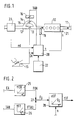
- FIG. 1 shows a rough overview of a fuel metering system for an internal combustion engine
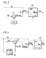
- FIGS. 2 to 4 block diagrams relating to the formation of fuel metering signals based on throttle valve angle and control signal of the bypass actuator.
- FIG. 1 shows a rough schematic overview of the elements of interaction in the fuel metering system according to the invention for an internal combustion engine.
- the internal combustion engine itself is designated 10. It has an exhaust pipe 11 and an intake line 12, which has a throttle valve 13 and a bypass duct 14 surrounding this throttle valve 13 in its interior.
- a bypass valve 15 which in turn is controlled by a bypass signal box 16.
- a single injection valve 18 is also drawn in the intake manifold 12, which may also represent several injection valves.
- An accelerator pedal bears the reference number 19. It determines the position of the throttle valve 13.
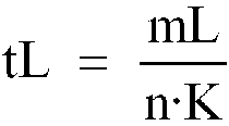
- an air mass meter 23 is shown, which measures the air mass flow mL taken in as the main load sensor.
- a pressure sensor (not shown) is conceivable, which detects the intake manifold absolute pressure as the main load signal.
- 20 denotes a control unit which receives the air mass signal mL and a position signal DK corresponding to the respective throttle valve position, as well as a speed signal n from a speed sensor 21 and further sensors, of which a temperature sensor 22 is indicated as a representative. On the output side, the control unit operates the injection valve 18 and the bypass signal box 16.
- control unit 20 forms injection signals and control signals for the bypass signal box 16 starting, inter alia, from a signal corresponding to the air mass signal mL , the position of the throttle valve 13 and the speed, detected by means of the speed sensor 21.
- FIG. 2 shows in the block diagram the formation of an additional basic injection signal tLF based on the signals DK as the throttle valve position and tau as the control signal for the signal box 16.
- the basic idea of the part of the fuel metering system shown in Figure 2 is that starting from the signals DK and tau a total area signal Fg is formed for the air flow area in the intake pipe, and this total area signal Fg, together with the rotational speed, subsequently serves as input variables of a map for outputting a basic measurement signal.
- the throttle valve position signal DK arrives at a first block 25, in which a characteristic curve is stored which forms a relationship between the throttle valve angle DK and the surface DK.
- An area signal FDK is thus present on the output side of block 25.
- control signal tau for the bypass signal box 16 arrives at a block 26 in which a characteristic curve Ftau plotted against tau is stored.
- Both output signals of blocks 25 and 26 arrive at a summation point 27, in which a signal is generated with respect to the total area Fg.
- a basic injection signal tLF is then read out depending on the speed n and the total area Fg, the end letter F being used as a sign that the basic injection signal was formed over the area.
- the throttle valve position signal and the control signal tau for the bypass signal box 16 are converted into virtual area signals and the total area serves as an input variable for the characteristic diagram with regard to the basic injection signal or a generally usable load signal.
- the methods according to FIGS. 3 to 5 are alternatives that are easier to apply.
- Block 31 symbolizes the conversion of the Control signal tau by means of a throttle valve-specific variable ctau.
- the output variable of this block 31 is then a virtual throttle valve angle DKvtau, which is likewise fed to the summation point 30.
- On the output side of the summing point 30 then is a signal relating to the virtual throttle total angle DKVG available, which is then determined in a map 32 together with a speed signal, the Grundzumeßsignal tL W, based on a W inkelbetician.
- Figure 4 shows in principle the same subject as Figure 3, but supplemented by a controllability for the signal ctau, which acts on the block 31.
- the reason for this is that in the simplest method according to FIG. 3 the conversion of the bypass drive signal dew in virtual DK change is only correct for one DK position. A certain additional DK area requires fewer additional virtual twist angles with increasing DK opening. This is taken into account in FIG. 4 via a characteristic curve block 38, which is supplied with the signal DK on the input side. With this measure, the influence of the throttle valve position signal DK on the virtual bypass signal DKvtau can be adapted.
Landscapes
- Engineering & Computer Science (AREA)
- Chemical & Material Sciences (AREA)
- Combustion & Propulsion (AREA)
- Mechanical Engineering (AREA)
- General Engineering & Computer Science (AREA)
- Electrical Control Of Air Or Fuel Supplied To Internal-Combustion Engine (AREA)
Abstract
Description
- Die Erfindung geht aus von einem Kraftstoffzumeß Verfahren für eine Brennkraftmaschine nach der Gattung des Hauptanspruchs. Bekannt ist aus der DE-A-31 20 667 ein System, bei dem sich das Kraftstoffzumeßsignal aus zwei Komponenten zusammensetzt. Diese beiden Komponenten orientieren sich an den getrennten Luftflüssen über die Drosselklappe sowie durch den Bypasskanal zur Drosselklappe. Dabei kann der durch die Drosselklappe bestimmte Anteil sowohl ausgehend vom Positionssignal der Drosselklappe ermittelt werden, als auch mittels eines Luftmengenmessers, der unmittelbar vor der Drosselklappe angeordnet ist.
- Die DE 37 21 911 A1 betrifft eine Ansaugvolumenfühleinrichtung für eine Brennkraftmaschine. Diese Brennkraftmaschine weist im Luftansaugrohr eine Drosselklappe sowie einen steuerbaren Bypasskanal zur Drosselklappe auf. Zur genauen Abschätzung der der Brennkraftmaschine zugeführten Luftmenge wird die Drosselklappenstellung ermittelt und der ermittelte Wert dazu verwendet, den wirksamen Querschnitt der Ansaugleitung zu bestimmen. Dabei wird auch der Bypass bei der Ermittlung des wirksamen Querschnitts der Ansaugleitung mit einbezogen. Dies kann z.B. dadurch geschehen, daß der wirksame Querschnitt der Ansaugleitung beim jeweiligen Drosselklappenöffnungsgrad sowie der wirksame Querschnitt des Regelventils der Bapassleitung bestimmt und addiert werden, um den verfügbaren Gesamtquerschnitt zu erhalten.
- Es hat sich nun gezeigt, daß dieser Weg nicht immer optimale Ergebnisse zu liefern vermag. Aufgabe der Erfindung ist es deshalb, eine Alternative anzugeben, mit der der gesamte Luftfluß über Drosselklappe und Bypasskanal möglichst genau zu bestimmen ist.
- Das erfindungsgemäße Kraftstoffzumeß Verfahren nach den Merkmalen des Anspruchs 1 hat gegenüber dem bekannten System den Vorteil einer korrekten Bestimmung der erforderlichen Kraftstoffmenge und damit auch der Beibehaltung eines wenig schadstoffbelasteten Abgases auch in Übergangsbereichen.
- Weitere Vorteile der Erfindung ergeben sich in Verbindung mit dem Unteransprüch aus der nachfolgenden Beschreibung von Ausführungsbeispielen.
- Ausführungsbeispiele der Erfindung sind im folgenden näher beschrieben und erläutert. Dabei zeigen Figur 1 eine grobe Übersichtsdarstellung eines Kraftstoffzumeßsystems für eine Brennkraftmaschine, und die Figuren 2 bis 4 Blockschaltbilder bezüglich der Bildung von Kraftstoffzumeßsignalen ausgehend von Drosselklappenwinkel und Ansteuersignal des Bypass-Stellers.
- Figur 1 zeigt in grobschematischer Übersicht die Elemente des Zusammenwirkens beim erfindungsgemäßen Kraftstoffzumeßsystem für eine Brennkraftmaschine. Dabei ist die Brennkraftmaschine selbst mit 10 bezeichnet. Sie besitzt ein Abgasrohr 11 sowie eine Ansaugleitung 12, die in ihrem Inneren eine Drosselklappe 13 und einen diese Drosselklappe 13 umgebenden Bypasskanal 14 aufweist. Im Bypasskanal 14 selbst befindet sich eine Bypassklappe 15, die ihrerseits von einem Bypass-Stellwerk 16 angesteuert wird. Unmittelbar vor der Brennkraftmaschine 10 ist im Ansaugrohr 12 noch ein einzelnes Einspritzventil 18 gezeichnet, das auch gegebenenfalls stellvertretend für mehrere Einspritzventile steht. Ein Fahrpedal trägt die Bezugsziffer 19. Es bestimmt die Position der Drosselklappe 13. Vor der Drosselklappe mit Bypass ist ein Luftmassenmesser 23 dargestellt, der als Hauptlastgeber den angesaugten Luftmassenstrom mL mißt. Alternativ ist ein nicht eingezeichneter Druckfühler denkbar, der den Saugrohrabsolutdruck als Hauptlastsignal erfaßt. Mit 20 ist ein Steuergerät bezeichnet, das das Luftmassensignal mL und ein Positionssignal DK entsprechend der jeweiligen Drosselklappenstellung erhält, ferner ein Drehzahlsignal n von einem Drehzahlsensor 21 und weiteren Sensoren, von denen stellvertretend ein Temperatursensor 22 angegeben ist. Ausgangsseitig bedient das Steuergerät das Einspritzventil 18 sowie das Bypass-Stellwerk 16.
- Die aus Figur 1 ersichtliche Anordnung ist als solche bekannt und entspricht u. a. dem Stand der Technik nach der obengenannten DE-A 31 20 667. Dabei bildet das Steuergerät 20 Einspritzsignale sowie Steuersignale für das Bypass-Stellwerk 16 ausgehend u. a. von einem Signal entsprechend dem Luftmassensignal mL, der Position der Drosselklappe 13 sowie der Drehzahl, erfaßt mittels des Drehzahlsensors 21.
- Die Erfindung bezieht sich nun auf den Teil des Steuergerätes 20, der unabhängig von dem aus Luftmassensignal und Drehzahl berechneten Hauptgrundeinspritzsignal
- Dabei werden außerdem die Gesetzmäßigkeiten im Zusammenhang mit der Bildung des Ansteuersignals für das Bypass-Stellwerk 16, insbesondere zur Leerlaufstabilisierung als bekannt vorausgesetzt.
- Figur 2 zeigt im Blockschaltbild die Bildung eines Zusatz-Grundeinspritzsignals tLF ausgehend von den Signalen DK als der Drosselklappenposition sowie tau als dem Ansteuersignal für das Stellwerk 16. Grundgedanke des in Figur 2 dargestellten Teils des Kraftstoffzumeßsystems ist es, daß ausgehend von den Signalen DK und tau ein Gesantflächensignal Fg für die Luftdurchflußfläche im Ansaugrohr gebildet wird, und dieses Gesamtflächensignal Fg nachfolgend zusammen mit der Drehzahl als Eingangsgrößen eines Kennfeldes zur Ausgabe eines Grundzumeßsignals dient. Dazu gelangt das Drosselklappenpositionssignal DK zu einem ersten Block 25, in dem eine Kennlinie abgelegt ist, die einen Zusammenhang zwischen Drosselklappenwinkel DK und der Fläche DK bildet. Ausgangsseitig des Blocks 25 steht somit ein Flächensignal FDK an. Entsprechend gelangt das Ansteuersignal tau für das Bypass-Stellwerk 16 zu einem Block 26, in dem eine Kennlinie Ftau aufgetragen über tau abgespeichert ist. Beide Ausgangssignale der Blöcke 25 und 26 gelangen zu einem Summationspunkt 27, in dem ein Signal bezüglich der Gesamtfläche Fg entsteht. Im nachfolgenden Kennfeld 28 wird dann abhängig von Drehzahl n und der Gesamtfläche Fg ein Grundeinspritzsignal tLF ausgelesen, wobei der Endbuchstabe F als Kennzeichnung dafür verwendet wurde, daß das Grundeinspritzsignal über die Fläche gebildet wurde.
- Wesentlich beim Gegenstand von Figur 2 ist, daß das Drosselklappenpositionssignal sowie das Ansteuersignal tau für das Bypass-Stellwerk 16 in virtuelle Flächensignale umgewandelt wird und die Gesamtfläche als Eingangsgröße für das Kennfeld bezüglich des Grundeinspritzsignales bzw. eines allgemein verwendbaren Lastsignals dient. Da die Flächen jedoch nicht direkt meßbar sind und somit eine Applikation schwierig ist, sind die Verfahren nach Figur 3 bis 5 leichter zu applizierende Alternativen.
- Beim Gegenstand von Figur 3 wird nicht - wie bei Figur 2 - auf die Fläche abgehoben, sondern auf einen gesamten, virtuellen Drosselklappenwinkel und davon ausgehend ein Grundeinspritzsignal tLW bestimmt, wobei W für Winkel steht. Der Grundgedanke liegt darin, daß die Öffnungsfläche des Bypass-Stellers die durch tau gegeben ist, umgerechnet wird in einen virtuellen Winkel, um den die DK zusätzlich zu ihrer tatsächlichen Stellung geöffnet werden müßte, um die gleiche zusätzliche Fläche freizugeben, wie der Bypass-Steller. Eingangsgrößen sind wiederum das Signal DK bezüglich des Drosselklappenwinkels sowie das Ansteuersignal für das Bypass-Stellwerk 16. Während nun das Drosselklappensignal DK unmittelbar auf einen Summationspunkt 30 geführt ist, gelangt das Signal tau über einen Block 31 zum Summationspunkt 30. Block 31 symbolisiert die Umrechnung des Ansteuersignals tau mittels einer drosselklappenspezifischen Größe ctau. Ausgangsqröße dieses Blocks 31 ist dann ein virtueller Drosselklappenwinkel DKvtau, der ebenfalls der Summationsstelle 30 zugeführt wird. Ausgangsseitig der Summationsstelle 30 steht dann ein Signal bezüglich des virtuellen Drosselklappengesamtwinkels DKvg zur Verfügung, der anschließend in einem Kennfeld 32 zusammen mit einem Drehzahlsignal das Grundzumeßsignal tLW, basierend auf einer Winkelbestimmung bestimmt.
- Figur 4 zeigt prinzipiell den gleichen Gegenstand wie Figur 3, jedoch ergänzt um eine Steuerbarkeit für das Signal ctau, das auf den Block 31 einwirkt. Der Grund dafür liegt darin, daß in dem einfachsten Verfahren nach Figur 3 die Umrechnung des Bypass-Ansteuersignals tau in virtuelle DK-Änderung nur für eine DK-Stellung richtig ist. Eine bestimmte zusätzliche DK-Fläche erfordert nämlich mit zunehmender DK-Öffnung weniger zusätzlichen virtuellen Verdrehwinkel. Dies wird in Figur 4 über einen Kennlinienblock 38 berücksichtigt, der eingangsseitig mit dem Signal DK beaufschlagt wird. Mit dieser Maßnahme kann der Einfluß des Drosselklappenstellungssignal DK auf das virtuelle Bypass-Signal DKvtau angepaßt werden.
Claims (2)
- Kraftstoffzumeßverfahren für eine Brennkraftmaschine mit einer Drosselklappe (13) im Luftansaugrohr, einem steuerbaren Bypass (14,15) zur Drosselklapppe und einer Signalverarbeitungseinheit zur Bildung eines Grund-Kraftstoffzumeßsignals bzw. eines allgemein verwendbaren Lastsignals ausgehend von wenigstens den Größen Drosselklappenwinkel, Ansteuersignal des Bypass-stellers sowie der Drehzahl, wobei- das Grund-Kraftstoffzumeßsignal über die Bildung eines virtuellen Gesamtsignals (DKvg) und anschließender ergänzender drehzahlabhängiger Kennfeldwertausgabe ermittelt wird,
dadurch gekennzeichnet, daß- das virtuelle Gesamtsignal bzgl. des Drosselklappenwinkels (DKvg) durch Addition des Drosselklappenwinkels mit einem auf dem Bypass-Stellersignal (tau) beruhenden virtuellen Bypass-Winkel-Signal (DKvtau) gebildet wird. - Kraftstoffzumeßverfahren nach Anspruch 1, dadurch gekennzeichnet, daß das virtuelle Bypass-Winkel-Signal (DKvtau) ausgehend vom Bypass-Stellersignal (tau) und einer Größe ermittelt wird, die vorzugsweise eine Funktion der aktuellen Drosselklappenposition ist (38, GtauDK).
Applications Claiming Priority (3)
| Application Number | Priority Date | Filing Date | Title |
|---|---|---|---|
| DE4034473A DE4034473A1 (de) | 1990-10-30 | 1990-10-30 | Kraftstoffzumesssystem fuer eine brennkraftmaschine |
| DE4034473 | 1990-10-30 | ||
| PCT/DE1991/000800 WO1992008045A1 (de) | 1990-10-30 | 1991-10-10 | Kraftstoffzumesssystem für eine brennkraftmaschine |
Publications (2)
| Publication Number | Publication Date |
|---|---|
| EP0507901A1 EP0507901A1 (de) | 1992-10-14 |
| EP0507901B1 true EP0507901B1 (de) | 1996-03-27 |
Family
ID=6417308
Family Applications (1)
| Application Number | Title | Priority Date | Filing Date |
|---|---|---|---|
| EP91917580A Expired - Lifetime EP0507901B1 (de) | 1990-10-30 | 1991-10-10 | Kraftstoffzumesssystem für eine brennkraftmaschine |
Country Status (4)
| Country | Link |
|---|---|
| EP (1) | EP0507901B1 (de) |
| JP (1) | JP2999260B2 (de) |
| DE (2) | DE4034473A1 (de) |
| WO (1) | WO1992008045A1 (de) |
Families Citing this family (1)
| Publication number | Priority date | Publication date | Assignee | Title |
|---|---|---|---|---|
| IT1263579B (it) * | 1993-06-16 | 1996-08-27 | Weber Srl | Sistema per la regolazione della portata di aria aspirata da un motorea combustione interna. |
Family Cites Families (4)
| Publication number | Priority date | Publication date | Assignee | Title |
|---|---|---|---|---|
| US4873641A (en) * | 1986-07-03 | 1989-10-10 | Nissan Motor Company, Limited | Induction volume sensing arrangement for an internal combustion engine or the like |
| DE3737699A1 (de) * | 1987-11-06 | 1989-05-18 | Bayerische Motoren Werke Ag | Steuereinrichtung fuer die einer brennkraftmaschine zuzufuehrende kraftstoffmenge |
| US4951499A (en) * | 1988-06-24 | 1990-08-28 | Fuji Jukogyo Kabushiki Kaisha | Intake air calculating system for automotive engine |
| JP2818805B2 (ja) * | 1988-12-08 | 1998-10-30 | 富士重工業株式会社 | エンジンの燃料噴射制御装置 |
-
1990
- 1990-10-30 DE DE4034473A patent/DE4034473A1/de not_active Withdrawn
-
1991
- 1991-10-10 DE DE59107630T patent/DE59107630D1/de not_active Expired - Lifetime
- 1991-10-10 JP JP3516204A patent/JP2999260B2/ja not_active Expired - Lifetime
- 1991-10-10 WO PCT/DE1991/000800 patent/WO1992008045A1/de not_active Ceased
- 1991-10-10 EP EP91917580A patent/EP0507901B1/de not_active Expired - Lifetime
Also Published As
| Publication number | Publication date |
|---|---|
| JPH05502923A (ja) | 1993-05-20 |
| JP2999260B2 (ja) | 2000-01-17 |
| DE59107630D1 (de) | 1996-05-02 |
| WO1992008045A1 (de) | 1992-05-14 |
| DE4034473A1 (de) | 1992-05-07 |
| EP0507901A1 (de) | 1992-10-14 |
Similar Documents
| Publication | Publication Date | Title |
|---|---|---|
| DE19740915B4 (de) | Verfahren zum Betreiben einer Brennkraftmaschine | |
| EP1272753B1 (de) | Verfahren und vorrichtung zur steuerung einer brennkraftmaschine | |
| EP1402240B1 (de) | Verfahren und vorrichtung zur ermittlung einer temperaturgrösse in einer massenstromleitung | |
| DE19912317C5 (de) | Verfahren zur Regelung des Anteils der einer Brennkraftmaschine rückgeführten Abgasmenge | |
| DE19545221A1 (de) | Verfahren und Vorrichtung zur Steuerung einer Brennkraftmaschine | |
| DE4344960A1 (de) | System zur Regelung der Aufladung einer Brennkraftmaschine | |
| DE3520281A1 (de) | Regelsystem zum regeln des luft-brennstoff-gemisches einer brennkraftmaschine fuer kraftfahrzeuge | |
| EP0375710B1 (de) | Einstellsystem (steuerungs- und/oder regelungssystem) für kraftfahrzeuge | |
| EP0286644A1 (de) | Verfahren zur elektronischen bestimmung der kraftstoffmenge einer brennkraftmaschine. | |
| DE10041076B4 (de) | Verfahren zur Erkennung von fehlerhaften Veränderungen des Gasdurchflusses durch eine Abgasrückführleitung einer Brennkraftmaschine | |
| DE102005018272B4 (de) | Verfahren und Vorrichtung zum Betreiben einer Brennkraftmaschine | |
| EP0976922B1 (de) | Verfahren zur Drehmomenteinstellung | |
| DE19618385B4 (de) | Verfahren und Vorrichtung zur Steuerung einer Brennkraftmaschine | |
| EP1999352A1 (de) | Verfahren und vorrichtung zur regelung oder steuerung eines verdichters eines abgas-turboladers | |
| DE2449954C2 (de) | Rückführsystem für das Abgas eines Verbrennungsmotors | |
| DE19544022C2 (de) | Einrichtung zur Bereitstellung einer Höheninformation in einem Kraftfahrzeug, kartengestützter Ortungs- und Navigationsdatenträger, Einrichtung zur Steuerung einer Brennkraftmaschine unter Verwendung der Höheninformation und Einrichtung zur Diagnose abgasrelevanter Teile in einem Kraftfahrzeug | |
| DE3310577C2 (de) | ||
| EP0507901B1 (de) | Kraftstoffzumesssystem für eine brennkraftmaschine | |
| DE19935901B4 (de) | Verfahren und Vorrichtung zur Regelung einer Brennkraftmaschine | |
| DE4235503C2 (de) | Steuersystem für das Luft-/Kraftstoffverhältnis für Verbrennungsmotoren | |
| DE10018308B4 (de) | Verfahren zur Regelung des Anteils der einer Brennkraftmaschine rückgeführten Abgasmenge | |
| DE2245492A1 (de) | Kraftstoffzumessanlage | |
| DE19547644A1 (de) | Verfahren und Vorrichtung zur Steuerung der Kraftstoffzumessung in eine Brennkraftmaschine | |
| EP0719383B1 (de) | Verfahren und vorrichtung zum berechnen des durch ein ventil an einem verbrennungsmotor strömenden gasvolumens | |
| DE3417495C2 (de) | Verfahren und Vorrichtung zum Bestimmen der von einer Brennkraftmaschine angesaugten Luftmenge |
Legal Events
| Date | Code | Title | Description |
|---|---|---|---|
| PUAI | Public reference made under article 153(3) epc to a published international application that has entered the european phase |
Free format text: ORIGINAL CODE: 0009012 |
|
| 17P | Request for examination filed |
Effective date: 19920603 |
|
| AK | Designated contracting states |
Kind code of ref document: A1 Designated state(s): DE GB |
|
| 17Q | First examination report despatched |
Effective date: 19941114 |
|
| GRAH | Despatch of communication of intention to grant a patent |
Free format text: ORIGINAL CODE: EPIDOS IGRA |
|
| GRAA | (expected) grant |
Free format text: ORIGINAL CODE: 0009210 |
|
| AK | Designated contracting states |
Kind code of ref document: B1 Designated state(s): DE GB |
|
| REF | Corresponds to: |
Ref document number: 59107630 Country of ref document: DE Date of ref document: 19960502 |
|
| GBT | Gb: translation of ep patent filed (gb section 77(6)(a)/1977) |
Effective date: 19960613 |
|
| PLBI | Opposition filed |
Free format text: ORIGINAL CODE: 0009260 |
|
| PLBQ | Unpublished change to opponent data |
Free format text: ORIGINAL CODE: EPIDOS OPPO |
|
| PLBF | Reply of patent proprietor to notice(s) of opposition |
Free format text: ORIGINAL CODE: EPIDOS OBSO |
|
| 26 | Opposition filed |
Opponent name: VDO ADOLF SCHINDLING AG Effective date: 19961217 |
|
| PLBF | Reply of patent proprietor to notice(s) of opposition |
Free format text: ORIGINAL CODE: EPIDOS OBSO |
|
| PLBQ | Unpublished change to opponent data |
Free format text: ORIGINAL CODE: EPIDOS OPPO |
|
| PLAB | Opposition data, opponent's data or that of the opponent's representative modified |
Free format text: ORIGINAL CODE: 0009299OPPO |
|
| R26 | Opposition filed (corrected) |
Opponent name: VDO ADOLF SCHINDLING AG Effective date: 19961217 |
|
| PLBO | Opposition rejected |
Free format text: ORIGINAL CODE: EPIDOS REJO |
|
| PLBN | Opposition rejected |
Free format text: ORIGINAL CODE: 0009273 |
|
| STAA | Information on the status of an ep patent application or granted ep patent |
Free format text: STATUS: OPPOSITION REJECTED |
|
| 27O | Opposition rejected |
Effective date: 19970618 |
|
| REG | Reference to a national code |
Ref country code: GB Ref legal event code: IF02 |
|
| PGFP | Annual fee paid to national office [announced via postgrant information from national office to epo] |
Ref country code: GB Payment date: 20030930 Year of fee payment: 13 |
|
| PG25 | Lapsed in a contracting state [announced via postgrant information from national office to epo] |
Ref country code: GB Free format text: LAPSE BECAUSE OF NON-PAYMENT OF DUE FEES Effective date: 20041010 |
|
| GBPC | Gb: european patent ceased through non-payment of renewal fee |
Effective date: 20041010 |
|
| PGFP | Annual fee paid to national office [announced via postgrant information from national office to epo] |
Ref country code: DE Payment date: 20101217 Year of fee payment: 20 |
|
| REG | Reference to a national code |
Ref country code: DE Ref legal event code: R071 Ref document number: 59107630 Country of ref document: DE |
|
| REG | Reference to a national code |
Ref country code: DE Ref legal event code: R071 Ref document number: 59107630 Country of ref document: DE |
|
| PG25 | Lapsed in a contracting state [announced via postgrant information from national office to epo] |
Ref country code: DE Free format text: LAPSE BECAUSE OF EXPIRATION OF PROTECTION Effective date: 20111011 |