EP0507569A2 - Batterieladevorrichtung mit temperaturempfindlichem Schalter - Google Patents
Batterieladevorrichtung mit temperaturempfindlichem Schalter Download PDFInfo
- Publication number
- EP0507569A2 EP0507569A2 EP92302869A EP92302869A EP0507569A2 EP 0507569 A2 EP0507569 A2 EP 0507569A2 EP 92302869 A EP92302869 A EP 92302869A EP 92302869 A EP92302869 A EP 92302869A EP 0507569 A2 EP0507569 A2 EP 0507569A2
- Authority
- EP
- European Patent Office
- Prior art keywords
- battery
- cut
- out switch
- temperature
- battery charger
- Prior art date
- Legal status (The legal status is an assumption and is not a legal conclusion. Google has not performed a legal analysis and makes no representation as to the accuracy of the status listed.)
- Granted
Links
Images
Classifications
-
- H02J7/977—
Definitions
- the conventional charger is involved in a multitude of parts and complex structure so that the production cannot be accomplished at a reasonable cost and reliability.
- the present invention relates to a battery charger with a temperature control magnetic switch for storage battery coupling with a magnet providing sticking function as operative conditions to form a circuit; when battery is saturated with charging and temperature control magnetic switch trips out the circuit may automatically switch into minor current for sticking to charge, and further by means of attraction provided by the magnet on battery charger to enable temperature control magnetic switch to maintain open circuit until battery is removed from the charger and temperature is so reduced as to reach the condition of restoration for said temperature control magnetic switch. Said minor current for sticking to charge is thus obtained through the constant-closed connections of temperature control magnetic switch being parallel connected limiter resistance.
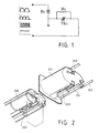
- FIG. 1 is a diagram showing the circuit of the battery charger with magnet for breaker sticking purpose and having temperature control magnetic switch-based automatic charging cut-off device.
- FIG. 2 is a diagramatic view showing the structure of the battery charger with magnet for breaker sticking purpose and having temperature control magnetic switch-based automatic charging cut-off device.
- the conventional automatic cut-off charger comprising voltage or current detection device being consisted in electronic component assemblies for charging the battery with temperature control switch in order to switch the charger into stick charging at some rated 0.1 C of battery (10% current of rated AH) when battery is saturated with charging or gets rather hot.
- the conventional circuits are involved in complex parts so that the production cannot be accomplished at reasonable cost.
- the present invention relates to a battery charger with a temperature control magnetic switch for storage battery coupling with a magnet providing sticking function as operative conditions to form a circuit; when battery is saturated with charging and temperature control magnetic switch trips out the circuit may automatically switch into minor current for sticking to charge, and further by means of attraction provided by the magnet on battery charger to enable temperature control magnetic switch to maintain open circuit until battery is removed from the charger and temperature is so reduced as to reach the condition of restoration for said temperature control magnetic switch. Said minor current for sticking to charge is thus obtained through the constant-closed connections of temperature control magnetic switch being parallel connected limiter resistance.
- FIG. 1 it is a diagram showing the circuit of the battery charger with magnet for breaker sticking purpose and having temperature control magnetic switch-based automatic charging cut-off device, comprising: power supply is DC, semi-wave DC, full-wave DC, intermittent pulse DC or weeping-wave DC; chargeable battery B O is built in constant closed temperature control switch TS O ; choking resistance R1 is parallel connected to constant-close connections of temperature control magnetic switch for being controlled by temperature control circuit, when the temperature of chargeable battery rises more than preset temperature and temperature control magnetic swtich trips out and gets breaker state, due to the limitation of the value of resistance impedance it can maintain topping charge for chargeable battery, and the attraction of magnet on the battery charger may retain temperature control magnetic switch at open-circuit state until power OFF or battery being removed and the loop being interrupted for restoration.
- power supply is DC, semi-wave DC, full-wave DC, intermittent pulse DC or weeping-wave DC
- chargeable battery B O is built in constant closed temperature control switch TS O
- choking resistance R1
- the conditions for the restoration of said circuit device include:
- FIG. 2 it is a diagramatic view showing the structure of the battery charger with magnet for breaker sticking purpose and having temperature control magnetic switch-based automatic charging cut-off device, comprising: a battery charger 201 is an independent structure for engaging chargeable battery and has electrodes corresponding to those of battery and particularly the positive and negative electrode 202, 203 and further including electrode 204 provided for control or indication purpose; said independent structure also including transformer and other elements for commutating, indication and control purpose; a magnet 205 is mounted at battery charger 201 perfectly coupling with temperature control magnetic switch when battery is engaged with the battery charger, and in order to attract the reed of said trip-out temperature control switch due to the sake of temperature rising to enable the reed to appear consistently open-circuit until the temperature drops down and enable the magnet break away from the temperature control magnetic switch; a chargeable battery 206 accomdated at least one set of battery and includes constant-close type temperature control magnetic switch 207 at a proper position, each PIN of said constant-close type temperature control magnetic switch 207 is parallel connected limit
- the present invention relates to connect constant-close temperature switch of chargeable battery with magnet set on the battery charger to apply magnetism to maintain breaker state when temperature control switch trips out due to over-temperature condition in order to enable the circuit to switch into limiting or partly limiting topping charge by means of limiter resistance impedance value when the temperature of chargeable battery is over high whereby chargeable battery is permitted for charging persistantly until it is removed or the temperature of temperature control magnetic switch is reduced to reach the point of restoration.
- the invention includes the following preferred features:
- the conditions for the restoration of said circuit device include:
Landscapes
- Charge And Discharge Circuits For Batteries Or The Like (AREA)
- Secondary Cells (AREA)
Applications Claiming Priority (2)
| Application Number | Priority Date | Filing Date | Title |
|---|---|---|---|
| GB9107102 | 1991-04-05 | ||
| GB9107102A GB2254497A (en) | 1991-04-05 | 1991-04-05 | Battery charger with magnetically latched temperature-responsive cut-out |
Publications (3)
| Publication Number | Publication Date |
|---|---|
| EP0507569A2 true EP0507569A2 (de) | 1992-10-07 |
| EP0507569A3 EP0507569A3 (en) | 1993-06-16 |
| EP0507569B1 EP0507569B1 (de) | 1997-02-05 |
Family
ID=10692655
Family Applications (1)
| Application Number | Title | Priority Date | Filing Date |
|---|---|---|---|
| EP92302869A Expired - Lifetime EP0507569B1 (de) | 1991-04-05 | 1992-04-01 | Batterieladevorrichtung mit temperaturempfindlichem Schalter |
Country Status (8)
| Country | Link |
|---|---|
| US (1) | US5250892A (de) |
| EP (1) | EP0507569B1 (de) |
| JP (1) | JP2572024Y2 (de) |
| CN (1) | CN2143020Y (de) |
| AT (1) | ATE148811T1 (de) |
| DE (1) | DE69217265T2 (de) |
| ES (1) | ES2097868T3 (de) |
| GB (1) | GB2254497A (de) |
Cited By (2)
| Publication number | Priority date | Publication date | Assignee | Title |
|---|---|---|---|---|
| US5689173A (en) * | 1995-02-07 | 1997-11-18 | Sanyo Electric Co., Ltd. | Battery pack |
| EP2065998A1 (de) * | 2007-09-11 | 2009-06-03 | Yen-Chung Jao | Batterieaufbau und Ladegerät, das auf den Batterieaufbau abgestimmt ist |
Families Citing this family (10)
| Publication number | Priority date | Publication date | Assignee | Title |
|---|---|---|---|---|
| JPH09219932A (ja) * | 1996-02-13 | 1997-08-19 | Alps Electric Co Ltd | ワイヤレス機器の充電装置 |
| US6326767B1 (en) | 1999-03-30 | 2001-12-04 | Shoot The Moon Products Ii, Llc | Rechargeable battery pack charging system with redundant safety systems |
| USD516502S1 (en) | 2000-06-09 | 2006-03-07 | Shoot The Moon Products Ii, Llc | Rechargeable battery pack |
| US6326766B1 (en) | 2000-06-09 | 2001-12-04 | Shoot The Moon Products Ii, Llc | Rechargable battery pack and battery pack charger with safety mechanisms |
| US6534956B2 (en) * | 2001-04-30 | 2003-03-18 | Tai-Her Yang | Thermostatic automatic cutoff charging device |
| DE10214368B4 (de) * | 2002-03-30 | 2007-09-13 | Robert Bosch Gmbh | Energiespeichermodul und dessen Verwendung für ein Elektrogerät |
| WO2007016191A2 (en) * | 2005-07-27 | 2007-02-08 | Flaugher David J | Battery chargers and methods for extended battery life |
| US9787083B2 (en) | 2012-12-06 | 2017-10-10 | Twin-Star International, Inc. | Overheat-resistant power cord and method |
| KR101876027B1 (ko) * | 2016-06-03 | 2018-07-06 | 현대자동차주식회사 | 친환경 차량의 ldc 제어 장치 및 그 방법 |
| CN109185921B (zh) * | 2018-09-21 | 2023-09-08 | 温州市诚芯电子有限公司 | 一种高集成度电子点烟器芯片 |
Family Cites Families (6)
| Publication number | Priority date | Publication date | Assignee | Title |
|---|---|---|---|---|
| FR1124505A (fr) * | 1955-03-25 | 1956-10-12 | Accumulateurs Fixes | Dispositif de protection pour batteries étanches |
| US3935525A (en) * | 1974-09-30 | 1976-01-27 | The Black And Decker Manufacturing Company | Battery charging circuit with thermostat control |
| US3928792A (en) * | 1975-02-24 | 1975-12-23 | Gen Electric | Method of resetting thermostat used with temperature controlled charging |
| US4045720A (en) * | 1976-05-04 | 1977-08-30 | Richard Bernard Alexandres | Automatic resetting temperature controlled battery changing system |
| US4164719A (en) * | 1978-04-03 | 1979-08-14 | Gould Inc. | Load management apparatus for residential load centers |
| US5031987A (en) * | 1990-01-02 | 1991-07-16 | Sundstrand Data Control, Inc. | Fiber optic thermal switch utilizing frustrated total internal reflection readout |
-
1991
- 1991-04-05 GB GB9107102A patent/GB2254497A/en not_active Withdrawn
- 1991-05-27 JP JP1991037537U patent/JP2572024Y2/ja not_active Expired - Lifetime
-
1992
- 1992-03-31 US US07/861,003 patent/US5250892A/en not_active Expired - Fee Related
- 1992-04-01 AT AT92302869T patent/ATE148811T1/de not_active IP Right Cessation
- 1992-04-01 EP EP92302869A patent/EP0507569B1/de not_active Expired - Lifetime
- 1992-04-01 DE DE69217265T patent/DE69217265T2/de not_active Expired - Fee Related
- 1992-04-01 ES ES92302869T patent/ES2097868T3/es not_active Expired - Lifetime
- 1992-04-04 CN CN92205710U patent/CN2143020Y/zh not_active Expired - Lifetime
Cited By (2)
| Publication number | Priority date | Publication date | Assignee | Title |
|---|---|---|---|---|
| US5689173A (en) * | 1995-02-07 | 1997-11-18 | Sanyo Electric Co., Ltd. | Battery pack |
| EP2065998A1 (de) * | 2007-09-11 | 2009-06-03 | Yen-Chung Jao | Batterieaufbau und Ladegerät, das auf den Batterieaufbau abgestimmt ist |
Also Published As
| Publication number | Publication date |
|---|---|
| ATE148811T1 (de) | 1997-02-15 |
| JP2572024Y2 (ja) | 1998-05-20 |
| CN2143020Y (zh) | 1993-09-29 |
| JPH04131147U (ja) | 1992-12-02 |
| ES2097868T3 (es) | 1997-04-16 |
| US5250892A (en) | 1993-10-05 |
| EP0507569B1 (de) | 1997-02-05 |
| GB2254497A (en) | 1992-10-07 |
| EP0507569A3 (en) | 1993-06-16 |
| DE69217265D1 (de) | 1997-03-20 |
| GB9107102D0 (en) | 1991-05-22 |
| DE69217265T2 (de) | 1997-06-05 |
Similar Documents
| Publication | Publication Date | Title |
|---|---|---|
| US6777910B2 (en) | Rechargeable battery packs | |
| US5480734A (en) | Rechargeable accumulator | |
| US3667026A (en) | Automatic temperature responsive battery charging circuit | |
| JP2961853B2 (ja) | 二次電池の保護装置 | |
| EP0507569A2 (de) | Batterieladevorrichtung mit temperaturempfindlichem Schalter | |
| US4766361A (en) | Battery charger having an interlocking assembly for accommodating increased charging rate capacity | |
| US5291118A (en) | Device for detecting connection or disconnection of a battery to an electric charger | |
| US4965462A (en) | Stand-by power supply | |
| US5247238A (en) | Battery charger automatic cut-off circuit | |
| EP0773618A2 (de) | Batterieladesystem | |
| US4045720A (en) | Automatic resetting temperature controlled battery changing system | |
| US4112201A (en) | Power source unit | |
| JP2002204525A (ja) | ブレーカとブレーカを内蔵するパック電池 | |
| JP3267825B2 (ja) | 充電器および携帯端末機器の構造 | |
| GB2192102A (en) | Battery protection and charging unit | |
| EP0100753B1 (de) | Batterieladegerät | |
| US3340454A (en) | Rechargeable battery-operated vacuum cleaner | |
| JP2932592B2 (ja) | 充電装置 | |
| JP2584574Y2 (ja) | 充電を自動的に停止させる電池充電回路 | |
| CN219960186U (zh) | 一种电池包及其防失控充放电电路 | |
| JPH10144285A (ja) | 蓄電池装置 | |
| US3866105A (en) | Battery-recharging device for indicating lamp | |
| KR100866712B1 (ko) | 이차전지 안정화 장치 | |
| JPH079569Y2 (ja) | ニツケルカドミウム電池の充電装置 | |
| EP0408365A2 (de) | Batterielader |
Legal Events
| Date | Code | Title | Description |
|---|---|---|---|
| PUAI | Public reference made under article 153(3) epc to a published international application that has entered the european phase |
Free format text: ORIGINAL CODE: 0009012 |
|
| AK | Designated contracting states |
Kind code of ref document: A2 Designated state(s): AT BE CH DE DK ES FR GB GR IT LI LU MC NL PT SE |
|
| PUAL | Search report despatched |
Free format text: ORIGINAL CODE: 0009013 |
|
| AK | Designated contracting states |
Kind code of ref document: A3 Designated state(s): AT BE CH DE DK ES FR GB GR IT LI LU MC NL PT SE |
|
| 17P | Request for examination filed |
Effective date: 19940221 |
|
| 17Q | First examination report despatched |
Effective date: 19940411 |
|
| GRAG | Despatch of communication of intention to grant |
Free format text: ORIGINAL CODE: EPIDOS AGRA |
|
| GRAG | Despatch of communication of intention to grant |
Free format text: ORIGINAL CODE: EPIDOS AGRA |
|
| GRAH | Despatch of communication of intention to grant a patent |
Free format text: ORIGINAL CODE: EPIDOS IGRA |
|
| GRAH | Despatch of communication of intention to grant a patent |
Free format text: ORIGINAL CODE: EPIDOS IGRA |
|
| GRAA | (expected) grant |
Free format text: ORIGINAL CODE: 0009210 |
|
| ITF | It: translation for a ep patent filed | ||
| AK | Designated contracting states |
Kind code of ref document: B1 Designated state(s): AT BE CH DE DK ES FR GB GR IT LI LU MC NL PT SE |
|
| PG25 | Lapsed in a contracting state [announced via postgrant information from national office to epo] |
Ref country code: GR Free format text: LAPSE BECAUSE OF FAILURE TO SUBMIT A TRANSLATION OF THE DESCRIPTION OR TO PAY THE FEE WITHIN THE PRESCRIBED TIME-LIMIT Effective date: 19970205 Ref country code: DK Effective date: 19970205 |
|
| REF | Corresponds to: |
Ref document number: 148811 Country of ref document: AT Date of ref document: 19970215 Kind code of ref document: T |
|
| REG | Reference to a national code |
Ref country code: CH Ref legal event code: NV Representative=s name: KELLER & PARTNER PATENTANWAELTE AG Ref country code: CH Ref legal event code: EP |
|
| REF | Corresponds to: |
Ref document number: 69217265 Country of ref document: DE Date of ref document: 19970320 |
|
| ET | Fr: translation filed | ||
| REG | Reference to a national code |
Ref country code: ES Ref legal event code: FG2A Ref document number: 2097868 Country of ref document: ES Kind code of ref document: T3 |
|
| PG25 | Lapsed in a contracting state [announced via postgrant information from national office to epo] |
Ref country code: LU Free format text: LAPSE BECAUSE OF NON-PAYMENT OF DUE FEES Effective date: 19970430 |
|
| PG25 | Lapsed in a contracting state [announced via postgrant information from national office to epo] |
Ref country code: PT Effective date: 19970505 |
|
| PGFP | Annual fee paid to national office [announced via postgrant information from national office to epo] |
Ref country code: AT Payment date: 19971002 Year of fee payment: 6 |
|
| PGFP | Annual fee paid to national office [announced via postgrant information from national office to epo] |
Ref country code: CH Payment date: 19971010 Year of fee payment: 6 |
|
| PGFP | Annual fee paid to national office [announced via postgrant information from national office to epo] |
Ref country code: BE Payment date: 19971013 Year of fee payment: 6 |
|
| PG25 | Lapsed in a contracting state [announced via postgrant information from national office to epo] |
Ref country code: MC Effective date: 19971031 |
|
| PLBE | No opposition filed within time limit |
Free format text: ORIGINAL CODE: 0009261 |
|
| STAA | Information on the status of an ep patent application or granted ep patent |
Free format text: STATUS: NO OPPOSITION FILED WITHIN TIME LIMIT |
|
| 26N | No opposition filed | ||
| PG25 | Lapsed in a contracting state [announced via postgrant information from national office to epo] |
Ref country code: AT Free format text: LAPSE BECAUSE OF NON-PAYMENT OF DUE FEES Effective date: 19980401 |
|
| PG25 | Lapsed in a contracting state [announced via postgrant information from national office to epo] |
Ref country code: LI Free format text: LAPSE BECAUSE OF NON-PAYMENT OF DUE FEES Effective date: 19980430 Ref country code: CH Free format text: LAPSE BECAUSE OF NON-PAYMENT OF DUE FEES Effective date: 19980430 Ref country code: BE Free format text: LAPSE BECAUSE OF NON-PAYMENT OF DUE FEES Effective date: 19980430 |
|
| PGFP | Annual fee paid to national office [announced via postgrant information from national office to epo] |
Ref country code: ES Payment date: 19981002 Year of fee payment: 7 |
|
| PGFP | Annual fee paid to national office [announced via postgrant information from national office to epo] |
Ref country code: SE Payment date: 19981008 Year of fee payment: 7 |
|
| BERE | Be: lapsed |
Owner name: YANG TAI-HER Effective date: 19980430 |
|
| REG | Reference to a national code |
Ref country code: CH Ref legal event code: PL |
|
| PG25 | Lapsed in a contracting state [announced via postgrant information from national office to epo] |
Ref country code: SE Free format text: LAPSE BECAUSE OF NON-PAYMENT OF DUE FEES Effective date: 19990402 |
|
| PG25 | Lapsed in a contracting state [announced via postgrant information from national office to epo] |
Ref country code: ES Free format text: LAPSE BECAUSE OF NON-PAYMENT OF DUE FEES Effective date: 19990405 |
|
| PGFP | Annual fee paid to national office [announced via postgrant information from national office to epo] |
Ref country code: GB Payment date: 19991001 Year of fee payment: 8 |
|
| PGFP | Annual fee paid to national office [announced via postgrant information from national office to epo] |
Ref country code: DE Payment date: 19991028 Year of fee payment: 8 |
|
| PGFP | Annual fee paid to national office [announced via postgrant information from national office to epo] |
Ref country code: NL Payment date: 19991029 Year of fee payment: 8 Ref country code: FR Payment date: 19991029 Year of fee payment: 8 |
|
| EUG | Se: european patent has lapsed |
Ref document number: 92302869.0 |
|
| PG25 | Lapsed in a contracting state [announced via postgrant information from national office to epo] |
Ref country code: GB Free format text: LAPSE BECAUSE OF NON-PAYMENT OF DUE FEES Effective date: 20000401 |
|
| PG25 | Lapsed in a contracting state [announced via postgrant information from national office to epo] |
Ref country code: NL Free format text: LAPSE BECAUSE OF NON-PAYMENT OF DUE FEES Effective date: 20001101 |
|
| GBPC | Gb: european patent ceased through non-payment of renewal fee |
Effective date: 20000401 |
|
| PG25 | Lapsed in a contracting state [announced via postgrant information from national office to epo] |
Ref country code: FR Free format text: LAPSE BECAUSE OF NON-PAYMENT OF DUE FEES Effective date: 20001229 |
|
| NLV4 | Nl: lapsed or anulled due to non-payment of the annual fee |
Effective date: 20001101 |
|
| PG25 | Lapsed in a contracting state [announced via postgrant information from national office to epo] |
Ref country code: DE Free format text: LAPSE BECAUSE OF NON-PAYMENT OF DUE FEES Effective date: 20010201 |
|
| REG | Reference to a national code |
Ref country code: FR Ref legal event code: ST |
|
| REG | Reference to a national code |
Ref country code: ES Ref legal event code: FD2A Effective date: 20010503 |
|
| PG25 | Lapsed in a contracting state [announced via postgrant information from national office to epo] |
Ref country code: IT Free format text: LAPSE BECAUSE OF NON-PAYMENT OF DUE FEES;WARNING: LAPSES OF ITALIAN PATENTS WITH EFFECTIVE DATE BEFORE 2007 MAY HAVE OCCURRED AT ANY TIME BEFORE 2007. THE CORRECT EFFECTIVE DATE MAY BE DIFFERENT FROM THE ONE RECORDED. Effective date: 20050401 |