EP0507569B1 - Batterieladevorrichtung mit temperaturempfindlichem Schalter - Google Patents
Batterieladevorrichtung mit temperaturempfindlichem Schalter Download PDFInfo
- Publication number
- EP0507569B1 EP0507569B1 EP92302869A EP92302869A EP0507569B1 EP 0507569 B1 EP0507569 B1 EP 0507569B1 EP 92302869 A EP92302869 A EP 92302869A EP 92302869 A EP92302869 A EP 92302869A EP 0507569 B1 EP0507569 B1 EP 0507569B1
- Authority
- EP
- European Patent Office
- Prior art keywords
- battery
- temperature
- cut
- out switch
- temperature control
- Prior art date
- Legal status (The legal status is an assumption and is not a legal conclusion. Google has not performed a legal analysis and makes no representation as to the accuracy of the status listed.)
- Expired - Lifetime
Links
Images
Classifications
-
- H02J7/977—
Definitions
- the conventional charger involves in a multitude of parts and complex structure so that the production cannot be accomplished at a reasonable cost and reliability.
- the present invention relates to a battery charger with a temperature control magnetic switch for storage battery coupling with a magnet providing sticking function as operative conditions to form a circuit; when battery is saturated with charging and temperature control magnetic switch trips out the circuit may automatically switch into minor current for sticking to charge, and further by means of attraction provided by the magnet on battery charger to enable temperature control magnetic switch to maintain open circuit until battery is removed from the charger and temperature is so reduced as to reach the condition of restoration for said temperature control magnetic switch. Said minor current for sticking to charge is thus obtained through the constant-closed connections of temperature control magnetic switch being parallel connected limiter resistance.
- US patent No. 4 045 720 discloses an automatically resetting battery charging circuit in that there is a main fast charging circuit and a trickle charging circuit. Initially both the fast charging and trickle charging circuits operate to charge the battery. Most of the charging is carried out by the main charging circuit. Once the battery is almost charged, it begins to heat up. Once the battery has reached a predetermined temperature, a detector, normally a bi-metallic strip, opens to break the main fast charging circuit. The trickle circuit is maintained and continues to top up the battery continuously. As the main charging circuit is broken by the temperature switch the current passing through the trickle circuit increases and this increasing current causes a relay to break the main charging circuit second place so that the battery cools down the main charging circuit is not reconnected.
- a detector normally a bi-metallic strip
- the bi-metallic switch would close to restart the main charging of the battery.
- the battery which is being charged is removed from the circuit, which is normally effected by removing a rechargeable power tool from recharging housing, which interrupts the trickle circuit causing the relay to close.
- the rechargeable tool can then be reinserted into the recharging housing after use in order to receive the recharging current from both the main charging circuit and the trickle charging circuit.
- a battery charger has a temperature sensitive cut out switch for cutting off the main charging current when the temperature of the battery exceeds a predetermined temperature, and latching means resettable by the user characterised in that the latching means includes a permanent magnet which tends to maintain the temperature sensitive cut-out switch (207) in the OFF state whilst the temperature of the battery (206) falls below the predetermined temperature, in that the battery charger (201) includes two separate parts, one of said parts including a battery compartment, and the other part being engaged therewith during charging, in that said cut-out switch (207) is located on one of said parts and said magnetic latching means (205) is located on the other of said parts so as to act on the cut-out switch (207) when the two parts are so engaged, whereby said cut-out switch (207) can be re-set by the user disengaging said parts on completion of charging.
- Fig. 1 is a diagram showing the circuit of the battery charger with magnet for breaker sticking purpose and having temperature control magnetic switch-based automatic charging cut-off device.
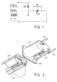
- FIG. 2 is a diagramatic view showing the structure of the battery charger with magnet for breaker sticking purpose and having temperature control magnetic switch-based automatic charging cut-off device.
- the conventional automatic cut-off charger comprising voltage or current detection device being consisted in electronic component assemblies for charging the battery with temperature control switch in order to switch the charger into stick charging at some rated 0.1 C of battery (10% current of rated AH) when battery is saturated with charging or gets rather hot.
- the conventional circuits involve complex parts so that the production cannot be accomplished at reasonable cost.
- the present invention relates to a battery charger with a temperature control magnetic switch for storage battery coupling with a magnet providing sticking function as operative conditions to form a circuit; when battery is saturated with charging and temperature control magnetic switch trips out the circuit may automatically switch into minor current for sticking to charge, and further by means of attraction provided by the magnet on battery charger to enable temperature control magnetic switch to maintain open circuit until battery is removed from the charger and temperature is so reduced as to reach the condition of restoration for said temperature control magnetic switch. Said minor current for sticking to charge is thus obtained through the constant-closed connections of temperature control magnetic switch being parallel connected limiter resistance.
- FIG. 1 it is a diagram showing the circuit of the battery charger with magnet for breaker sticking purpose and having temperature control magnetic switch-based automatic charging cut-off device, comprising:
- the conditions for the restoration of said circuit device include:
- FIG. 2 it is a diagrammatic view showing the structure of the battery charger with magnet for breaker sticking purpose and having temperature control magnetic switch-based automatic charging cut-off device, comprising:
- the present invention relates to connect constant-close temperature switch of chargeable battery with magnet set on the battery charger to apply magnetism to maintain breaker state when temperature control switch trips out due to over-temperature condition in order to enable the circuit to switch into limiting or partly limiting topping charge by means of limiter resistance impedance value when the temperature of chargeable battery is over high whereby chargeable battery is permitted for charging persistantly until it is removed or the temperature of temperature control magnetic switch is reduced to reach the point of restoration.
- the invention includes the following preferred features:
- the conditions for the restoration of said circuit device include:
Landscapes
- Charge And Discharge Circuits For Batteries Or The Like (AREA)
- Secondary Cells (AREA)
Claims (3)
- Batterieladevorrichtung (201) mit einem temperaturempfindlichem Ausschalter (207) zum Abschalten eines Hauptladestroms, wenn die Temperatur der Batterie (206) eine vorbestimmte Temperatur überschreitet, und einer durch den Benutzer zurücksetzbaren Zwischenspeichereinrichtung (205),
dadurch gekennzeichnet, daß
die Zwischenspeichereinrichtung einen Permanentmagneten aufweist zum Erhalt des temperaturempfindlichen Ausschalters (207) in dem ausgeschalteten Zustand, solange die Temperatur der Batterie (206) unter die vorbestimmte Temperatur sinkt, daß die Batterieladevorrichtung (201) zwei getrennte Teile aufweist, wobei einer der Teile ein Batteriefach aufweist und der andere Teil während der Ladung mit diesem in Eingriff steht, daß sich der Ausschalter (207) auf einem der Teile befindet und sich die magnetische Zwischenspeichereinrichtung (205) auf dem anderen Teil befindet, damit auf den Ausschalter (207) eingewirkt wird, wenn die beiden Teile miteinander in Eingriff stehen, wodurch der Ausschalter (207) durch das Lösen der Bereiche bei Abschluß der Ladung durch den Benutzer zurückgesetzt werden kann. - Batterieladevorrichtung (201) nach Anspruch 1,
dadurch gekennzeichnet, daß
die magnetische Zwischenspeichereinrichtung (205) den Ausschalter (207) in dessen ausgeschalteten Zustand bei Umgebungstemperatur bis zu einem Zurücksetzen durch den Benutzer erhält. - Batterieladevorrichtung (201) nach Anspruch 1 oder 2,
dadurch gekennzeichnet, daß
der Ausschalter (207) mittels eines Strombegrenzungswiderstands umgangen wird, durch den der Batterie (206) ein verringerter Strom zugeführt wird, der zum Erhalt der Batterieladung ausreichend ist, während der Ausschalter (207) im ausgeschalteten Zustand belassen wird.
Applications Claiming Priority (2)
| Application Number | Priority Date | Filing Date | Title |
|---|---|---|---|
| GB9107102A GB2254497A (en) | 1991-04-05 | 1991-04-05 | Battery charger with magnetically latched temperature-responsive cut-out |
| GB9107102 | 1991-04-05 |
Publications (3)
| Publication Number | Publication Date |
|---|---|
| EP0507569A2 EP0507569A2 (de) | 1992-10-07 |
| EP0507569A3 EP0507569A3 (en) | 1993-06-16 |
| EP0507569B1 true EP0507569B1 (de) | 1997-02-05 |
Family
ID=10692655
Family Applications (1)
| Application Number | Title | Priority Date | Filing Date |
|---|---|---|---|
| EP92302869A Expired - Lifetime EP0507569B1 (de) | 1991-04-05 | 1992-04-01 | Batterieladevorrichtung mit temperaturempfindlichem Schalter |
Country Status (8)
| Country | Link |
|---|---|
| US (1) | US5250892A (de) |
| EP (1) | EP0507569B1 (de) |
| JP (1) | JP2572024Y2 (de) |
| CN (1) | CN2143020Y (de) |
| AT (1) | ATE148811T1 (de) |
| DE (1) | DE69217265T2 (de) |
| ES (1) | ES2097868T3 (de) |
| GB (1) | GB2254497A (de) |
Families Citing this family (12)
| Publication number | Priority date | Publication date | Assignee | Title |
|---|---|---|---|---|
| US5689173A (en) * | 1995-02-07 | 1997-11-18 | Sanyo Electric Co., Ltd. | Battery pack |
| JPH09219932A (ja) * | 1996-02-13 | 1997-08-19 | Alps Electric Co Ltd | ワイヤレス機器の充電装置 |
| US6326767B1 (en) | 1999-03-30 | 2001-12-04 | Shoot The Moon Products Ii, Llc | Rechargeable battery pack charging system with redundant safety systems |
| USD516502S1 (en) | 2000-06-09 | 2006-03-07 | Shoot The Moon Products Ii, Llc | Rechargeable battery pack |
| US6326766B1 (en) | 2000-06-09 | 2001-12-04 | Shoot The Moon Products Ii, Llc | Rechargable battery pack and battery pack charger with safety mechanisms |
| US6534956B2 (en) * | 2001-04-30 | 2003-03-18 | Tai-Her Yang | Thermostatic automatic cutoff charging device |
| DE10214368B4 (de) * | 2002-03-30 | 2007-09-13 | Robert Bosch Gmbh | Energiespeichermodul und dessen Verwendung für ein Elektrogerät |
| WO2007016191A2 (en) * | 2005-07-27 | 2007-02-08 | Flaugher David J | Battery chargers and methods for extended battery life |
| TWI350019B (en) * | 2007-09-11 | 2011-10-01 | Yen Chung Jao | Battery structure and power supply device of the battery structure |
| US9787083B2 (en) | 2012-12-06 | 2017-10-10 | Twin-Star International, Inc. | Overheat-resistant power cord and method |
| KR101876027B1 (ko) * | 2016-06-03 | 2018-07-06 | 현대자동차주식회사 | 친환경 차량의 ldc 제어 장치 및 그 방법 |
| CN109185921B (zh) * | 2018-09-21 | 2023-09-08 | 温州市诚芯电子有限公司 | 一种高集成度电子点烟器芯片 |
Family Cites Families (6)
| Publication number | Priority date | Publication date | Assignee | Title |
|---|---|---|---|---|
| FR1124505A (fr) * | 1955-03-25 | 1956-10-12 | Accumulateurs Fixes | Dispositif de protection pour batteries étanches |
| US3935525A (en) * | 1974-09-30 | 1976-01-27 | The Black And Decker Manufacturing Company | Battery charging circuit with thermostat control |
| US3928792A (en) * | 1975-02-24 | 1975-12-23 | Gen Electric | Method of resetting thermostat used with temperature controlled charging |
| US4045720A (en) * | 1976-05-04 | 1977-08-30 | Richard Bernard Alexandres | Automatic resetting temperature controlled battery changing system |
| US4164719A (en) * | 1978-04-03 | 1979-08-14 | Gould Inc. | Load management apparatus for residential load centers |
| US5031987A (en) * | 1990-01-02 | 1991-07-16 | Sundstrand Data Control, Inc. | Fiber optic thermal switch utilizing frustrated total internal reflection readout |
-
1991
- 1991-04-05 GB GB9107102A patent/GB2254497A/en not_active Withdrawn
- 1991-05-27 JP JP1991037537U patent/JP2572024Y2/ja not_active Expired - Lifetime
-
1992
- 1992-03-31 US US07/861,003 patent/US5250892A/en not_active Expired - Fee Related
- 1992-04-01 EP EP92302869A patent/EP0507569B1/de not_active Expired - Lifetime
- 1992-04-01 DE DE69217265T patent/DE69217265T2/de not_active Expired - Fee Related
- 1992-04-01 AT AT92302869T patent/ATE148811T1/de not_active IP Right Cessation
- 1992-04-01 ES ES92302869T patent/ES2097868T3/es not_active Expired - Lifetime
- 1992-04-04 CN CN92205710U patent/CN2143020Y/zh not_active Expired - Lifetime
Also Published As
| Publication number | Publication date |
|---|---|
| DE69217265D1 (de) | 1997-03-20 |
| EP0507569A3 (en) | 1993-06-16 |
| JPH04131147U (ja) | 1992-12-02 |
| GB2254497A (en) | 1992-10-07 |
| DE69217265T2 (de) | 1997-06-05 |
| ATE148811T1 (de) | 1997-02-15 |
| EP0507569A2 (de) | 1992-10-07 |
| CN2143020Y (zh) | 1993-09-29 |
| US5250892A (en) | 1993-10-05 |
| JP2572024Y2 (ja) | 1998-05-20 |
| GB9107102D0 (en) | 1991-05-22 |
| ES2097868T3 (es) | 1997-04-16 |
Similar Documents
| Publication | Publication Date | Title |
|---|---|---|
| US6326766B1 (en) | Rechargable battery pack and battery pack charger with safety mechanisms | |
| JP2961853B2 (ja) | 二次電池の保護装置 | |
| US5480734A (en) | Rechargeable accumulator | |
| US6326767B1 (en) | Rechargeable battery pack charging system with redundant safety systems | |
| EP0507569B1 (de) | Batterieladevorrichtung mit temperaturempfindlichem Schalter | |
| US6859014B2 (en) | Method for rapid charge control in lithium batteries | |
| US5963019A (en) | Battery pack with battery protection circuit | |
| KR100293742B1 (ko) | 과충전으로부터 전지셀을 보호하기 위한 장치 및 그의 방법 | |
| US3667026A (en) | Automatic temperature responsive battery charging circuit | |
| US4965462A (en) | Stand-by power supply | |
| EP0773618A2 (de) | Batterieladesystem | |
| TW200529532A (en) | Protection methods, protection circuits and protective devices for secondary batteries, a power tool, charger and battery pack adapted to provide protection against fault conditions in the battery pack | |
| US4045720A (en) | Automatic resetting temperature controlled battery changing system | |
| WO1996023325A1 (en) | A bypass switching apparatus for a ptc protected battery and charger | |
| US5247238A (en) | Battery charger automatic cut-off circuit | |
| JP2002204525A (ja) | ブレーカとブレーカを内蔵するパック電池 | |
| JP3443238B2 (ja) | 保護回路を備えるパック電池 | |
| US3928792A (en) | Method of resetting thermostat used with temperature controlled charging | |
| GB2192102A (en) | Battery protection and charging unit | |
| JP2932592B2 (ja) | 充電装置 | |
| KR100866712B1 (ko) | 이차전지 안정화 장치 | |
| JP2542278B2 (ja) | 満充電になっている二次電池の再充電防止装置並びにバッテリパック及びその充電器 | |
| JPH10144285A (ja) | 蓄電池装置 | |
| JP2584574Y2 (ja) | 充電を自動的に停止させる電池充電回路 | |
| KR900009226Y1 (ko) | 밧데리의 급속 충전 제어회로 |
Legal Events
| Date | Code | Title | Description |
|---|---|---|---|
| PUAI | Public reference made under article 153(3) epc to a published international application that has entered the european phase |
Free format text: ORIGINAL CODE: 0009012 |
|
| AK | Designated contracting states |
Kind code of ref document: A2 Designated state(s): AT BE CH DE DK ES FR GB GR IT LI LU MC NL PT SE |
|
| PUAL | Search report despatched |
Free format text: ORIGINAL CODE: 0009013 |
|
| AK | Designated contracting states |
Kind code of ref document: A3 Designated state(s): AT BE CH DE DK ES FR GB GR IT LI LU MC NL PT SE |
|
| 17P | Request for examination filed |
Effective date: 19940221 |
|
| 17Q | First examination report despatched |
Effective date: 19940411 |
|
| GRAG | Despatch of communication of intention to grant |
Free format text: ORIGINAL CODE: EPIDOS AGRA |
|
| GRAG | Despatch of communication of intention to grant |
Free format text: ORIGINAL CODE: EPIDOS AGRA |
|
| GRAH | Despatch of communication of intention to grant a patent |
Free format text: ORIGINAL CODE: EPIDOS IGRA |
|
| GRAH | Despatch of communication of intention to grant a patent |
Free format text: ORIGINAL CODE: EPIDOS IGRA |
|
| GRAA | (expected) grant |
Free format text: ORIGINAL CODE: 0009210 |
|
| ITF | It: translation for a ep patent filed | ||
| AK | Designated contracting states |
Kind code of ref document: B1 Designated state(s): AT BE CH DE DK ES FR GB GR IT LI LU MC NL PT SE |
|
| PG25 | Lapsed in a contracting state [announced via postgrant information from national office to epo] |
Ref country code: GR Free format text: LAPSE BECAUSE OF FAILURE TO SUBMIT A TRANSLATION OF THE DESCRIPTION OR TO PAY THE FEE WITHIN THE PRESCRIBED TIME-LIMIT Effective date: 19970205 Ref country code: DK Effective date: 19970205 |
|
| REF | Corresponds to: |
Ref document number: 148811 Country of ref document: AT Date of ref document: 19970215 Kind code of ref document: T |
|
| REG | Reference to a national code |
Ref country code: CH Ref legal event code: NV Representative=s name: KELLER & PARTNER PATENTANWAELTE AG Ref country code: CH Ref legal event code: EP |
|
| REF | Corresponds to: |
Ref document number: 69217265 Country of ref document: DE Date of ref document: 19970320 |
|
| ET | Fr: translation filed | ||
| REG | Reference to a national code |
Ref country code: ES Ref legal event code: FG2A Ref document number: 2097868 Country of ref document: ES Kind code of ref document: T3 |
|
| PG25 | Lapsed in a contracting state [announced via postgrant information from national office to epo] |
Ref country code: LU Free format text: LAPSE BECAUSE OF NON-PAYMENT OF DUE FEES Effective date: 19970430 |
|
| PG25 | Lapsed in a contracting state [announced via postgrant information from national office to epo] |
Ref country code: PT Effective date: 19970505 |
|
| PGFP | Annual fee paid to national office [announced via postgrant information from national office to epo] |
Ref country code: AT Payment date: 19971002 Year of fee payment: 6 |
|
| PGFP | Annual fee paid to national office [announced via postgrant information from national office to epo] |
Ref country code: CH Payment date: 19971010 Year of fee payment: 6 |
|
| PGFP | Annual fee paid to national office [announced via postgrant information from national office to epo] |
Ref country code: BE Payment date: 19971013 Year of fee payment: 6 |
|
| PG25 | Lapsed in a contracting state [announced via postgrant information from national office to epo] |
Ref country code: MC Effective date: 19971031 |
|
| PLBE | No opposition filed within time limit |
Free format text: ORIGINAL CODE: 0009261 |
|
| STAA | Information on the status of an ep patent application or granted ep patent |
Free format text: STATUS: NO OPPOSITION FILED WITHIN TIME LIMIT |
|
| 26N | No opposition filed | ||
| PG25 | Lapsed in a contracting state [announced via postgrant information from national office to epo] |
Ref country code: AT Free format text: LAPSE BECAUSE OF NON-PAYMENT OF DUE FEES Effective date: 19980401 |
|
| PG25 | Lapsed in a contracting state [announced via postgrant information from national office to epo] |
Ref country code: LI Free format text: LAPSE BECAUSE OF NON-PAYMENT OF DUE FEES Effective date: 19980430 Ref country code: CH Free format text: LAPSE BECAUSE OF NON-PAYMENT OF DUE FEES Effective date: 19980430 Ref country code: BE Free format text: LAPSE BECAUSE OF NON-PAYMENT OF DUE FEES Effective date: 19980430 |
|
| PGFP | Annual fee paid to national office [announced via postgrant information from national office to epo] |
Ref country code: ES Payment date: 19981002 Year of fee payment: 7 |
|
| PGFP | Annual fee paid to national office [announced via postgrant information from national office to epo] |
Ref country code: SE Payment date: 19981008 Year of fee payment: 7 |
|
| BERE | Be: lapsed |
Owner name: YANG TAI-HER Effective date: 19980430 |
|
| REG | Reference to a national code |
Ref country code: CH Ref legal event code: PL |
|
| PG25 | Lapsed in a contracting state [announced via postgrant information from national office to epo] |
Ref country code: SE Free format text: LAPSE BECAUSE OF NON-PAYMENT OF DUE FEES Effective date: 19990402 |
|
| PG25 | Lapsed in a contracting state [announced via postgrant information from national office to epo] |
Ref country code: ES Free format text: LAPSE BECAUSE OF NON-PAYMENT OF DUE FEES Effective date: 19990405 |
|
| PGFP | Annual fee paid to national office [announced via postgrant information from national office to epo] |
Ref country code: GB Payment date: 19991001 Year of fee payment: 8 |
|
| PGFP | Annual fee paid to national office [announced via postgrant information from national office to epo] |
Ref country code: DE Payment date: 19991028 Year of fee payment: 8 |
|
| PGFP | Annual fee paid to national office [announced via postgrant information from national office to epo] |
Ref country code: NL Payment date: 19991029 Year of fee payment: 8 Ref country code: FR Payment date: 19991029 Year of fee payment: 8 |
|
| EUG | Se: european patent has lapsed |
Ref document number: 92302869.0 |
|
| PG25 | Lapsed in a contracting state [announced via postgrant information from national office to epo] |
Ref country code: GB Free format text: LAPSE BECAUSE OF NON-PAYMENT OF DUE FEES Effective date: 20000401 |
|
| PG25 | Lapsed in a contracting state [announced via postgrant information from national office to epo] |
Ref country code: NL Free format text: LAPSE BECAUSE OF NON-PAYMENT OF DUE FEES Effective date: 20001101 |
|
| GBPC | Gb: european patent ceased through non-payment of renewal fee |
Effective date: 20000401 |
|
| PG25 | Lapsed in a contracting state [announced via postgrant information from national office to epo] |
Ref country code: FR Free format text: LAPSE BECAUSE OF NON-PAYMENT OF DUE FEES Effective date: 20001229 |
|
| NLV4 | Nl: lapsed or anulled due to non-payment of the annual fee |
Effective date: 20001101 |
|
| PG25 | Lapsed in a contracting state [announced via postgrant information from national office to epo] |
Ref country code: DE Free format text: LAPSE BECAUSE OF NON-PAYMENT OF DUE FEES Effective date: 20010201 |
|
| REG | Reference to a national code |
Ref country code: FR Ref legal event code: ST |
|
| REG | Reference to a national code |
Ref country code: ES Ref legal event code: FD2A Effective date: 20010503 |
|
| PG25 | Lapsed in a contracting state [announced via postgrant information from national office to epo] |
Ref country code: IT Free format text: LAPSE BECAUSE OF NON-PAYMENT OF DUE FEES;WARNING: LAPSES OF ITALIAN PATENTS WITH EFFECTIVE DATE BEFORE 2007 MAY HAVE OCCURRED AT ANY TIME BEFORE 2007. THE CORRECT EFFECTIVE DATE MAY BE DIFFERENT FROM THE ONE RECORDED. Effective date: 20050401 |