EP0507032A2 - Kompakte Reifen-Hubvorrichtung - Google Patents
Kompakte Reifen-Hubvorrichtung Download PDFInfo
- Publication number
- EP0507032A2 EP0507032A2 EP91310317A EP91310317A EP0507032A2 EP 0507032 A2 EP0507032 A2 EP 0507032A2 EP 91310317 A EP91310317 A EP 91310317A EP 91310317 A EP91310317 A EP 91310317A EP 0507032 A2 EP0507032 A2 EP 0507032A2
- Authority
- EP
- European Patent Office
- Prior art keywords
- spool
- cable
- drive shaft
- lift unit
- tire
- Prior art date
- Legal status (The legal status is an assumption and is not a legal conclusion. Google has not performed a legal analysis and makes no representation as to the accuracy of the status listed.)
- Withdrawn
Links
- 230000008878 coupling Effects 0.000 claims description 10
- 238000010168 coupling process Methods 0.000 claims description 10
- 238000005859 coupling reaction Methods 0.000 claims description 10
- 239000002184 metal Substances 0.000 claims description 10
- 230000008901 benefit Effects 0.000 claims description 5
- 239000000463 material Substances 0.000 claims description 4
- 230000004044 response Effects 0.000 claims description 4
- 229920003023 plastic Polymers 0.000 claims description 3
- 239000004033 plastic Substances 0.000 claims description 3
- 230000000717 retained effect Effects 0.000 claims 1
- 239000012255 powdered metal Substances 0.000 description 12
- 238000010276 construction Methods 0.000 description 5
- 230000004048 modification Effects 0.000 description 4
- 238000012986 modification Methods 0.000 description 4
- 238000004804 winding Methods 0.000 description 4
- 210000005069 ears Anatomy 0.000 description 2
- 230000002093 peripheral effect Effects 0.000 description 2
- 230000004323 axial length Effects 0.000 description 1
- 230000009977 dual effect Effects 0.000 description 1
- 230000003028 elevating effect Effects 0.000 description 1
- 238000009434 installation Methods 0.000 description 1
- 230000013011 mating Effects 0.000 description 1
- 230000007246 mechanism Effects 0.000 description 1
- 229910001220 stainless steel Inorganic materials 0.000 description 1
- 239000010935 stainless steel Substances 0.000 description 1
Images
Classifications
-
- B—PERFORMING OPERATIONS; TRANSPORTING
- B62—LAND VEHICLES FOR TRAVELLING OTHERWISE THAN ON RAILS
- B62D—MOTOR VEHICLES; TRAILERS
- B62D43/00—Spare wheel stowing, holding, or mounting arrangements
- B62D43/02—Spare wheel stowing, holding, or mounting arrangements external to the vehicle body
- B62D43/04—Spare wheel stowing, holding, or mounting arrangements external to the vehicle body attached beneath the vehicle body
- B62D43/045—Spare wheel stowing, holding, or mounting arrangements external to the vehicle body attached beneath the vehicle body the wheel or its cradle being attached to one or more chains or cables for handling
-
- B—PERFORMING OPERATIONS; TRANSPORTING
- B66—HOISTING; LIFTING; HAULING
- B66D—CAPSTANS; WINCHES; TACKLES, e.g. PULLEY BLOCKS; HOISTS
- B66D1/00—Rope, cable, or chain winding mechanisms; Capstans
-
- B—PERFORMING OPERATIONS; TRANSPORTING
- B66—HOISTING; LIFTING; HAULING
- B66D—CAPSTANS; WINCHES; TACKLES, e.g. PULLEY BLOCKS; HOISTS
- B66D1/00—Rope, cable, or chain winding mechanisms; Capstans
- B66D1/02—Driving gear
- B66D1/14—Power transmissions between power sources and drums or barrels
Definitions
- the tire lift unit with one way coupling means which permit quick winding of the cable on the spool and retraction of the spare tire to its elevated stored position with the aid of a power driven tool. This minimizes the time required to assemble a spare tire onto a motor vehicle during original assembly of the motor vehicle, but prevents the tire from being removed without the use of the crank.
- the present invention is directed to an improved tire (spare wheel) lift unit of the type disclosed in above-mentioned U.S. Patent No. 4,969,630, and is defined in claim 1.
- the unit embodying the invention is capable of providing some or all of the desirable features and advantages mentioned above.
- the tire lift unit incorporates a spool formed by two powdered metal plate members which interfit to define an annular track having a width substantially the same as the diameter of the cable so that the cable wraps upon itself in a spiral overlapping manner.
- One of the plate members has an integral hub portion which defines an undercut cavity for receiving a fitting secured to the inner end portion of the cable and also has a pair of recesses for receiving inwardly projecting lugs on the other plate member which also has an integrally formed ring gear.
- An external gear is disposed within the ring gear and is integrally formed with a control plate as a single powdered metal part, and the control plate receives a powdered metal eccentric cam supported for rotation by the drive shaft.
- the eccentric cam may be integrally formed with a torque-limiting clutch cam which has lobes for engaging resilient wire springs carried by a powered metal clutch plate secured for rotation with the drive shaft.
- An anti-backup feature is provided by simultaneous engagement between leading and trailing surfaces on two teeth of the ring gear and corresponding trailing and leading surfaces on two adjacent teeth of the external gear.
- the extension of the cable and the unwinding of the spool is provided with a downstop in the form of a pawl having a passage through which the cable passes. The pawl is pivoted by the cable to engage a notch within the spool when the spool continues to rotate after the cable is fully extended.
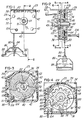
- FIG. 1 shows a tire lift assembly or unit 25 which includes a housing 28 formed by a pair of inverted L-shaped sheet metal mounting plates or brackets 32 and 34 spaced on opposite sides of a frame-like housing body or shroud 36 molded of a rigid plastics material.
- the brackets 32 and 34 have outwardly projecting flanges 38 and 39 which have holes (not shown) for securing the brackets to the body or frame of a motor vehicle by means threaded fasteners.
- the mounting brackets 32 and 34 are secured together by a set of three rivets 42 having tubular end portions which are flared after the unit 25 is assembled.
- Each side of the shroud 36 has three locating studs 43 which project into corresponding holes within the adjacent mounting bracket.
- the sheet metal plates or brackets 32 and 34 are formed with corresponding center bearing hubs 44 and 46 which rotatably support a drive shaft 48.
- the shaft 48 includes an enlarged cylindrical end portion 49 having a cross hole 51 for connecting an actuator, and the shaft also includes a drive portion having a pair of diametrically opposite flats 52 adjacent a circular stop flange 53.
- annular spool 60 is supported within the housing 28 for rotation on the drive shaft 48 and includes a first one-piece powdered metal plate member 62 having a cylindrical flange portion 63 with circumferentially spaced circular holes 64 to reduce material and weight.
- the plate member 62 also includes an integrally formed hub portion 68 which defines an undercut cavity 71 (FIG. 3) and a pair of circumferentially spaced recesses 72, all of which extend the full axial length of the hub portion 68.
- the spool 60 also includes a second powdered metal annular plate member 74 which slides axially onto the hub portion 68 of the plate member 62 and cooperates with the disk or flange portion 63 to define a narrow annular track 76.
- the track 76 has a width substantially the same as the diameter of a flexible stainless steel cable 80 which is wound within the track 76 in a spiral overlapping manner as shown in FIG. 3.
- a tubular fitting 82 (FIG. 3) is crimped or secured to the inner end portion of the cable 80 and is captured within the recess 71 to connect the inner end portion of the cable to the spool 60.
- another fitting or ferrule 84 is positively secured or crimped to the outer end portion of the cable 80 and supports a formed sheet metal lift member or plate 86.
- the lift plate 86 is adapted to be inserted through a center hole within a spare tire wheel and then positioned so that the opposite shoulders 88 engage the center portion of the wheel.
- the one-piece powdered metal plate member 74 of the spool 60 includes a pair of circumferentially spaced lugs or tabs 92 which project inwardly into the recesses 72 within the hub portion 68 of the plate member 62.
- the interfitting connection of the plate members 62 and 74 prevents rotation of the plate member 74 on the hub portion 68 of the plate member 62, and the plate member 74 also retains the inner end portion of the cable 80 and fitting 82 within the cavity 71 of the hub portion 68.
- the plate member 74 of the spool 60 also incorporates an integrally formed internal ring gear 96 which has inwardly projecting and circumferentially spaced teeth 98 all formed as integral part of the powdered metal plate member 74.
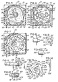
- a recess or notch 101 (FIGS. 4 & 7) is formed within the outer peripheral portion of the plate member 74 of the spool 60 and is adapted to receive a sheet metal pawl 103 which is pivotally supported by a cross pin or rivet 104.
- the pawl 103 is attached to a base portion 106 which is molded of a rigid plastics material and is also pivotally supported with the pawl 103 by the rivet 104.
- the base portion 106 includes an integrally molded pin 107 which projects through a hole within the pawl 103 and is hot-staked to secure the pawl 103 to the base portion 106.
- a channel or passage 109 is formed within the base portion 106 of the pawl 103, and the cable 80 extends through the passage immediately before the cable exits the housing 28 through a hole 111 within the shroud 36.
- the pawl 103 is in a retracted position as shown in FIG. 3.
- the counterclockwise movement of the inner end portion of the cable with the spool 60 is effective to pivot the pawl 103 clockwise so that the pawl engages the spool 60 within she notch 101 to prevent further counterclockwise rotation of the spool.
- the spool is rotated in a clockwise direction (FIG.
- the pawl 103 is cammed outwardly and pivoted by the cable to its retracted position (FIG. 3) where the pawl 103 does not interfere with rotation of the spool in either direction.
- a control plate 115 is formed of powdered metal and is integrally formed with an external gear 118 which is located within the internal ring gear 96 and has outwardly projecting peripherally spaced teeth 119.
- the one-piece control plate 115 and external gear 118 is mounted for rotation on an eccentric cam 120 which is also formed of powdered metal and is mounted for rotation on the drive shaft 48.
- the control plate 115 has an outwardly projecting ear portion 122 (FIG. 5) which has a slot 123 for receiving one of the rivets 42 to prevent rotation of the control plate while permitting the control plate to orbit with the external gear 118 in response to rotation of the cam 120.
- each of the inwardly projecting teeth 98 of the internal ring gear 96 and each of the outwardly projecting teeth 119 of the external gear 118 has leading and trailing edge surfaces.
- the smaller size of the rounded teeth 98 relative to the larger rounded teeth 119 and the shape of the teeth result in the leading and trailing surfaces of two spaced teeth 98 of the internal gear 96 being in simultaneous contact with corresponding trailing and leading surfaces on adjacent teeth 119 of the external gear 118 at the two points 124.
- This dual contact of the interfitting teeth 98 and 119 form an anti-backup feature for the spool 60. That is, a counterclockwise torque on the internal gear 96 (FIG. 4) due to the weight of a tire and tension within the cable 80, is ineffective to produce rotation of the external gear 118 on the cam 120.
- a torque limiting or slip clutch 125 maximizes the torque for rotating the spool 60 when the cable 80 is fully retracted onto the spool within the track 76.
- the clutch 125 is constructed in a manner similar to the construction of the torque limiting clutch disclosed in above-mentioned Patent No. 4,969,630.
- the clutch 125 includes a driven sheet metal disk or plate 128 having a center hole which receives a concentric hub or boss 129 on the cam 120 and has a keyway which receives an axially projecting key 132 on the cam 120 so that the clutch plate 128 drives the cam 120.
- the clutch plate 128 includes a pair of diametrically opposed ears 134 which project axially into curved portions 136 of a pair of arcuate leaf-type metal springs 138 having hook-shaped end portions 139.
- the springs 138 are carried by a clutch drive plate 142 which has a pair T-shaped cavities 143 for receiving and retaining the end portions 139 of the springs 138.
- the clutch drive plate 142 has a center hole 146 with double opposing flats 147 which receives the mating hub portion 52 of the drive shaft 48 (FIG. 2) so that the clutch plate 142 is positively driven by the drive shaft 48.
- the ears 134 cam the springs 138 inwardly to permit continued rotation of the plate 142 relative to the plate 128.
- the operation of the tire lift unit 25 is generally the same as the tire lift unit disclosed in above-mentioned Patent No. 4,969,630. That is, the high mechanical advantage provided by the orbital gear drive system requires multiple rotations of the drive shaft 48 to produce one rotation of the spool 60. Thus a heavy spare tire may be raised and lowered by the tire lift unit 25 in response to relatively low torque on the drive shaft 48.
- the down stop pawl 103 prevents further rotation of the spool 60 after the cable 80 is fully extended, and the torque limiting clutch 125 prevents the tire lift unit 25 from being damaged in the event an excessive torque is applied to the drive shaft 125 after the cable 80 is fully retracted on the spool 60 when the spare tire firmly engages the body of the motor vehicle.
- a drive shaft 158 is constructed the same as the drive shaft 48 but with the addition of a one direction coupling in the form of cam-type drive lugs 162 projecting outwardly from the shaft support 46 of the combined plate and mounting bracket 34.
- the ramp-shaped lugs 162 provide for inserting a spade-like bit between the lugs 162 and rotating the shaft clockwise (FIG. 9) with the aid of a power tool for winding the cable 80 onto the spool 60.
- the bit is rotated counterclockwise, the bit is cammed from the lugs 162 so the spool 60 may not be rotated in an opposite direction which would lower the spare tire onto the roadway surface.
- the one way drive lugs 162 provide an anti-theft means for quickly rotating the drive shaft 158 in only one direction and with the aid of a power driven tool.
- FIGS. 11 and 12 show another form of an anti-theft drive coupling for driving a shaft 168 which is constructed the same as the drive shaft 48 but includes a projecting end portion 169 with a reduced neck portion 171.
- the coupling for driving the shaft 168 in only one direction includes a hexagonal tubular fitting 173 having a cylindrical base portion 174 which carries a surrounding cylindrical sleeve 177.
- a cross pin 178 extends through a hole within the shaft 168 and has opposite end portions which engage a pair of diametrically opposite ramp or cam surfaces 181 formed within the base portion 174 of the drive coupling.
- a lock pin 183 is press-fitted through a hole within the fitting 173 and has an inner portion captured within the annular cavity surrounding the neck portion 171.
- the fitting 173 when the fitting 173 is urged inwardly on the shaft 168 and rotated in one direction, the fitting 173 rotates the drive shaft 168 due to engagement with the cross pin 178, as shown in FIG. 11. However, if the fitting 173 is rotated in the opposite direction, the fitting 173 shifts outwardly or axially on the end portion of the shaft 168 as a result of the cam surfaces 181 and until the fitting 173 rotates freely on the shaft 168.
- the lock pin 183 permits the fitting 173 to shift axially on the end portion 169 of the shaft 168 but prevents the fitting from being removed from the end portion, as shown in FIG. 12.
- a modification of a tire lift unit constructed in accordance with the invention incorporates a torque-limiting or slip clutch 190 in place of the slip clutch 125 described above.
- an eccentric cam 192 and a clutch cam 194 are formed of powdered metal as a single part and are supported for rotation by the drive shaft 48.
- the clutch cam 194 has three uniformly spaced rounded cam lobes 196 and is driven clockwise (FIG. 13) by a circular clutch disk or plate 198 which is also formed of powdered metal.
- the plate 198 has a center hole with double flats for receiving the drive portion 52 of the drive shaft 48, and the outer peripheral portion of the clutch plate 198 has a set of peripherally spaced offset portions or pockets 203 and 204 which receive opposite end portions of three wire springs 206 each having an angular end portion 207.
- the wire springs 206 engage the corresponding cam lobes 196 and drive the clutch cam 194 clockwise (FIG. 13).
- the wire springs 206 deform outwardly around the cam lobes 196 and permit the clutch plate 198 to rotate clockwise (FIG. 13) relative to the clutch cam 194.
- a tire lift unit constructed in accordance with the present invention provides desirable features and advantages.
- the construction of the tire lift unit 25, including the powdered metal parts which combine components significantly reduces the number of parts to produce the unit, thereby significantly reducing the costs of the parts and the time and labor required for assembling the parts.
- the continuous contact of the leading and trailing surfaces on the circumferentially spaced gear teeth at the two points 124 provides the drive mechanism with an anti-backup so that the cable 80 does not unwind slightly while driving the vehicle over a long period of time.
- Another desirable feature is provided by the downstop arm or pawl 103 which senses when the cable 80 is fully extended and stops the spool 60 from further rotation in the same direction.
- the drive couplings disclosed in connection with FIGS. 8-12 provide for quickly retracting the cable 80 and elevating the spare tire during assembly of the tire lift unit to the motor vehicle, but also prevent a person from extending the cable and lowering the spare tire without access to the crank which couples to the opposite end portion of the drive shaft.
- the construction of the torque-limiting clutch 190 disclosed in connection with FIGS. 13 and 14 provides a slip clutch which is simple and economical in construction and further reduces the overall cost of producing the tire lift unit.
Landscapes
- Engineering & Computer Science (AREA)
- Mechanical Engineering (AREA)
- Chemical & Material Sciences (AREA)
- Combustion & Propulsion (AREA)
- Transportation (AREA)
- Automobile Manufacture Line, Endless Track Vehicle, Trailer (AREA)
- Mechanical Operated Clutches (AREA)
- Gear Transmission (AREA)
- Braking Arrangements (AREA)
Applications Claiming Priority (2)
| Application Number | Priority Date | Filing Date | Title |
|---|---|---|---|
| US678605 | 1991-04-01 | ||
| US07/678,605 US5290014A (en) | 1991-04-01 | 1991-04-01 | Compact tire lift unit |
Publications (2)
| Publication Number | Publication Date |
|---|---|
| EP0507032A2 true EP0507032A2 (de) | 1992-10-07 |
| EP0507032A3 EP0507032A3 (en) | 1993-01-13 |
Family
ID=24723499
Family Applications (1)
| Application Number | Title | Priority Date | Filing Date |
|---|---|---|---|
| EP19910310317 Withdrawn EP0507032A3 (en) | 1991-04-01 | 1991-11-07 | Compact tire lift unit |
Country Status (4)
| Country | Link |
|---|---|
| US (1) | US5290014A (de) |
| EP (1) | EP0507032A3 (de) |
| JP (1) | JPH0516838A (de) |
| CA (1) | CA2054144C (de) |
Cited By (4)
| Publication number | Priority date | Publication date | Assignee | Title |
|---|---|---|---|---|
| EP0635420A1 (de) * | 1993-07-24 | 1995-01-25 | Metallifacture Limited | Hebevorrichtung |
| WO2009115817A3 (en) * | 2008-03-20 | 2009-11-26 | Ap Driveline Technologies Limited | Wheel winch |
| US9315224B2 (en) | 2013-09-11 | 2016-04-19 | Batz, S. Coop. | Spare wheel pickup assembly |
| US9764783B2 (en) | 2013-09-11 | 2017-09-19 | Batz, S.Coop. | Spare wheel pickup assembly |
Families Citing this family (18)
| Publication number | Priority date | Publication date | Assignee | Title |
|---|---|---|---|---|
| GB2304319B (en) * | 1995-08-15 | 1997-10-22 | Gec Alsthom Ltd | Method and apparatus for paying out, securing and hauling in a flexible elongate tensile member |
| US5664766A (en) * | 1996-05-17 | 1997-09-09 | Unique Concepts Ltd. | Winch with reverse rotation protection |
| WO1999050565A1 (en) * | 1998-03-31 | 1999-10-07 | Valley Industries, Inc. | Torque limiting cam |
| US5975498A (en) * | 1998-12-14 | 1999-11-02 | Deuer Manufacturing Inc. | Spare tire lift/carrier unit with dual retainers |
| US6443846B1 (en) | 2000-12-22 | 2002-09-03 | Edscha North America | Spare tire carrier torque-limiting slip mechanism |
| JP2001355865A (ja) * | 2001-04-16 | 2001-12-26 | Sharp Corp | 電気暖房器 |
| US20040041137A1 (en) * | 2001-12-12 | 2004-03-04 | Katsuji Shoji | Self-locking reduction device |
| US6871841B2 (en) * | 2002-11-06 | 2005-03-29 | Deuer Manufacturing Inc. | Apparatus for supporting a spare tire and wheel assembly on a motor vehicle |
| US7404544B2 (en) * | 2005-04-08 | 2008-07-29 | Dura Global Technologies, Inc. | Tire carrier disk clutch |
| US7226039B2 (en) * | 2005-09-12 | 2007-06-05 | Troy Engineered Components And Assemblies Corporation | Hoist assembly for a motor vehicle spare tire |
| US7487953B2 (en) * | 2005-09-12 | 2009-02-10 | Troy Engineered Components And Assemblies Corporation | Hoist assembly for a motor vehicle spare tire |
| EP2352981B1 (de) * | 2008-11-03 | 2015-04-08 | Redzone Robotics, Inc. | Vorrichtung zur röhreninspektion und verfahren zu ihrer verwendung |
| ES2406856B1 (es) * | 2011-12-06 | 2014-09-02 | Batz, S.Coop. | Unidad de recogida de ruedas de repuesto en vehículos |
| US9861033B2 (en) * | 2012-03-15 | 2018-01-09 | Shakespeare Company, Llc | Universally adaptable, easy to load trimmer head with free rotating bump knob |
| US9458664B2 (en) * | 2014-07-31 | 2016-10-04 | Nien Made Enterprise Co., Ltd. | Adjustable cord locker and window blind having such adjustable cord locker |
| WO2016127101A1 (en) | 2015-02-06 | 2016-08-11 | Milwaukee Electric Tool Corporation | Gas spring-powered fastener driver |
| IT201900009111A1 (it) * | 2019-06-17 | 2020-12-17 | Proma S P A | Dispositivo per sollevare ed abbassare una ruota di scorta di un veicolo, avente superfici di impegno. |
| CA3120518A1 (en) * | 2020-06-01 | 2021-12-01 | Utilicor Technologies Inc. | Excavation apparatus with supporting linkage |
Family Cites Families (22)
| Publication number | Priority date | Publication date | Assignee | Title |
|---|---|---|---|---|
| US2019512A (en) * | 1933-03-01 | 1935-11-05 | Columbus Mckinnon Chain Compan | Means for preventing reverse winding of a cable on a drum |
| US2686016A (en) * | 1949-10-20 | 1954-08-10 | Rudolph R Kilian | Fishing reel |
| US2830542A (en) * | 1953-06-22 | 1958-04-15 | Gen Motors Corp | Fluid pump |
| US3373625A (en) * | 1966-08-19 | 1968-03-19 | Gen Motors Corp | Backlash reducing mechanism |
| JPS5123171Y2 (de) * | 1971-12-30 | 1976-06-15 | ||
| US3865264A (en) * | 1972-10-10 | 1975-02-11 | Caddie Ind Inc | Spare tire mount |
| US3874536A (en) * | 1973-07-25 | 1975-04-01 | Yoshio Watanabe | Spare tire holder for an automobile |
| US3958771A (en) * | 1974-09-30 | 1976-05-25 | Everett Woodrow W | Fishing reel |
| GB1506244A (en) * | 1975-02-01 | 1978-04-05 | Manno Kogyo Co Ltd | Spare tyre carriers |
| US4043437A (en) * | 1975-12-19 | 1977-08-23 | Lipe-Rollway Corporation | Torque limiting clutch brake |
| JPS5943348B2 (ja) * | 1977-09-24 | 1984-10-22 | 三工機器株式会社 | 予備タイヤ保持装置の予備タイヤ盗難防止装置 |
| US4544136A (en) * | 1981-06-25 | 1985-10-01 | Joseph Deuer | Tire lift/carrier |
| US4969630A (en) * | 1981-06-25 | 1990-11-13 | Deuer Manufacturing Inc. | Tire lift/carrier |
| US4625947A (en) * | 1984-07-02 | 1986-12-02 | Deuer Manufacturing, Inc. | Tire lift/carrier |
| USRE33303E (en) * | 1981-06-25 | 1990-08-21 | Deuer Manufacturing Inc. | Tire lift/carrier |
| US4535973A (en) * | 1984-01-11 | 1985-08-20 | Kent Products, Inc. | Vehicle tire carrier |
| JPH02503550A (ja) * | 1988-03-18 | 1990-10-25 | スパートン コーポレーション | タイヤ持上/支持ウインチ用溝車板及びケーブル組立体 |
| US4915358A (en) * | 1988-07-05 | 1990-04-10 | Stallings Hulon D | Compound angle drive for raising and lowering vehicle spare tire |
| US5125628A (en) * | 1988-11-11 | 1992-06-30 | Sparton Corporation | Sheave and cable assembly for a tire lift/carrier winch |
| WO1990015773A2 (en) * | 1989-06-21 | 1990-12-27 | Sparton Corporation | Sheave assembly for a tire lift/carrier winch |
| US5060912A (en) * | 1989-10-23 | 1991-10-29 | David Guarr | Spare tire holder and wheel lock |
| US5120003A (en) * | 1990-08-02 | 1992-06-09 | Sacconi Roberto L | Changeable fishing reel cartridge with line |
-
1991
- 1991-04-01 US US07/678,605 patent/US5290014A/en not_active Expired - Lifetime
- 1991-10-24 CA CA002054144A patent/CA2054144C/en not_active Expired - Lifetime
- 1991-11-07 EP EP19910310317 patent/EP0507032A3/en not_active Withdrawn
- 1991-12-18 JP JP3335139A patent/JPH0516838A/ja active Pending
Cited By (4)
| Publication number | Priority date | Publication date | Assignee | Title |
|---|---|---|---|---|
| EP0635420A1 (de) * | 1993-07-24 | 1995-01-25 | Metallifacture Limited | Hebevorrichtung |
| WO2009115817A3 (en) * | 2008-03-20 | 2009-11-26 | Ap Driveline Technologies Limited | Wheel winch |
| US9315224B2 (en) | 2013-09-11 | 2016-04-19 | Batz, S. Coop. | Spare wheel pickup assembly |
| US9764783B2 (en) | 2013-09-11 | 2017-09-19 | Batz, S.Coop. | Spare wheel pickup assembly |
Also Published As
| Publication number | Publication date |
|---|---|
| US5290014A (en) | 1994-03-01 |
| CA2054144A1 (en) | 1992-10-02 |
| JPH0516838A (ja) | 1993-01-26 |
| CA2054144C (en) | 2001-09-18 |
| EP0507032A3 (en) | 1993-01-13 |
Similar Documents
| Publication | Publication Date | Title |
|---|---|---|
| EP0507032A2 (de) | Kompakte Reifen-Hubvorrichtung | |
| US7487953B2 (en) | Hoist assembly for a motor vehicle spare tire | |
| EP1394404B1 (de) | Seilstartvorrichtung | |
| US5125628A (en) | Sheave and cable assembly for a tire lift/carrier winch | |
| GB2348262A (en) | Tensioner lever | |
| US5415377A (en) | Sheave assembly for a tire lift/carrier winch | |
| JPH04110005U (ja) | 電動アンテナ装置 | |
| JP3718029B2 (ja) | オルダム継手をもったレジューサ | |
| US7226039B2 (en) | Hoist assembly for a motor vehicle spare tire | |
| US20020149008A1 (en) | Spare tire carrier | |
| GB2162046A (en) | Lock mechanism for seat belt webbing retractor | |
| US6007446A (en) | Drive unit | |
| EP0368526B1 (de) | Kupplung | |
| JPH0315657A (ja) | 内燃機関用リコイルスタータの爪 | |
| JPS62153566A (ja) | ロ−プ巻返し式スタ−タ | |
| JPH10513417A (ja) | ベルトテンショナーのための回転駆動装置 | |
| JP2024092318A (ja) | スロットル装置 | |
| JP2677976B2 (ja) | シートベルトウェブを格納するシートベルトのリトラクター | |
| US5520349A (en) | Adjustable automatic locking retractor | |
| CN221519475U (zh) | 一种后视镜 | |
| WO1993009009A1 (en) | Restraint belt retractor | |
| JPS6347048Y2 (de) | ||
| EP0635420B1 (de) | Hebevorrichtung | |
| JP3795637B2 (ja) | ウエビング巻取装置 | |
| CN103890377B (zh) | 机动车起动装置 |
Legal Events
| Date | Code | Title | Description |
|---|---|---|---|
| PUAI | Public reference made under article 153(3) epc to a published international application that has entered the european phase |
Free format text: ORIGINAL CODE: 0009012 |
|
| AK | Designated contracting states |
Kind code of ref document: A2 Designated state(s): AT DE GB |
|
| PUAL | Search report despatched |
Free format text: ORIGINAL CODE: 0009013 |
|
| AK | Designated contracting states |
Kind code of ref document: A3 Designated state(s): AT DE GB |
|
| STAA | Information on the status of an ep patent application or granted ep patent |
Free format text: STATUS: THE APPLICATION IS DEEMED TO BE WITHDRAWN |
|
| 18D | Application deemed to be withdrawn |
Effective date: 19930714 |