EP0506479B1 - Bildverarbeitungsgerät - Google Patents
Bildverarbeitungsgerät Download PDFInfo
- Publication number
- EP0506479B1 EP0506479B1 EP92302753A EP92302753A EP0506479B1 EP 0506479 B1 EP0506479 B1 EP 0506479B1 EP 92302753 A EP92302753 A EP 92302753A EP 92302753 A EP92302753 A EP 92302753A EP 0506479 B1 EP0506479 B1 EP 0506479B1
- Authority
- EP
- European Patent Office
- Prior art keywords
- image
- identification information
- image data
- visible
- input
- Prior art date
- Legal status (The legal status is an assumption and is not a legal conclusion. Google has not performed a legal analysis and makes no representation as to the accuracy of the status listed.)
- Expired - Lifetime
Links
Images


Classifications
-
- H—ELECTRICITY
- H04—ELECTRIC COMMUNICATION TECHNIQUE
- H04N—PICTORIAL COMMUNICATION, e.g. TELEVISION
- H04N1/00—Scanning, transmission or reproduction of documents or the like, e.g. facsimile transmission; Details thereof
- H04N1/00838—Preventing unauthorised reproduction
- H04N1/00856—Preventive measures
- H04N1/00864—Modifying the reproduction, e.g. outputting a modified copy of a scanned original
-
- G—PHYSICS
- G03—PHOTOGRAPHY; CINEMATOGRAPHY; ANALOGOUS TECHNIQUES USING WAVES OTHER THAN OPTICAL WAVES; ELECTROGRAPHY; HOLOGRAPHY
- G03G—ELECTROGRAPHY; ELECTROPHOTOGRAPHY; MAGNETOGRAPHY
- G03G21/00—Arrangements not provided for by groups G03G13/00 - G03G19/00, e.g. cleaning, elimination of residual charge
- G03G21/04—Preventing copies being made of an original
-
- G—PHYSICS
- G06—COMPUTING OR CALCULATING; COUNTING
- G06T—IMAGE DATA PROCESSING OR GENERATION, IN GENERAL
- G06T7/00—Image analysis
- G06T7/90—Determination of colour characteristics
-
- H—ELECTRICITY
- H04—ELECTRIC COMMUNICATION TECHNIQUE
- H04N—PICTORIAL COMMUNICATION, e.g. TELEVISION
- H04N1/00—Scanning, transmission or reproduction of documents or the like, e.g. facsimile transmission; Details thereof
- H04N1/00838—Preventing unauthorised reproduction
- H04N1/0084—Determining the necessity for prevention
- H04N1/00843—Determining the necessity for prevention based on recognising a copy prohibited original, e.g. a banknote
- H04N1/00848—Determining the necessity for prevention based on recognising a copy prohibited original, e.g. a banknote by detecting a particular original
-
- H—ELECTRICITY
- H04—ELECTRIC COMMUNICATION TECHNIQUE
- H04N—PICTORIAL COMMUNICATION, e.g. TELEVISION
- H04N1/00—Scanning, transmission or reproduction of documents or the like, e.g. facsimile transmission; Details thereof
- H04N1/00838—Preventing unauthorised reproduction
- H04N1/00856—Preventive measures
- H04N1/00864—Modifying the reproduction, e.g. outputting a modified copy of a scanned original
- H04N1/00867—Modifying the reproduction, e.g. outputting a modified copy of a scanned original with additional data, e.g. by adding a warning message
- H04N1/0087—Modifying the reproduction, e.g. outputting a modified copy of a scanned original with additional data, e.g. by adding a warning message with hidden additional data, e.g. data invisible to the human eye
-
- H—ELECTRICITY
- H04—ELECTRIC COMMUNICATION TECHNIQUE
- H04N—PICTORIAL COMMUNICATION, e.g. TELEVISION
- H04N1/00—Scanning, transmission or reproduction of documents or the like, e.g. facsimile transmission; Details thereof
- H04N1/00838—Preventing unauthorised reproduction
- H04N1/00856—Preventive measures
- H04N1/00864—Modifying the reproduction, e.g. outputting a modified copy of a scanned original
- H04N1/00872—Modifying the reproduction, e.g. outputting a modified copy of a scanned original by image quality reduction, e.g. distortion or blacking out
-
- H—ELECTRICITY
- H04—ELECTRIC COMMUNICATION TECHNIQUE
- H04N—PICTORIAL COMMUNICATION, e.g. TELEVISION
- H04N1/00—Scanning, transmission or reproduction of documents or the like, e.g. facsimile transmission; Details thereof
- H04N1/387—Composing, repositioning or otherwise geometrically modifying originals
- H04N1/3871—Composing, repositioning or otherwise geometrically modifying originals the composed originals being of different kinds, e.g. low- and high-resolution originals
-
- G—PHYSICS
- G06—COMPUTING OR CALCULATING; COUNTING
- G06T—IMAGE DATA PROCESSING OR GENERATION, IN GENERAL
- G06T2207/00—Indexing scheme for image analysis or image enhancement
- G06T2207/10—Image acquisition modality
- G06T2207/10004—Still image; Photographic image
- G06T2207/10008—Still image; Photographic image from scanner, fax or copier
-
- G—PHYSICS
- G06—COMPUTING OR CALCULATING; COUNTING
- G06T—IMAGE DATA PROCESSING OR GENERATION, IN GENERAL
- G06T2207/00—Indexing scheme for image analysis or image enhancement
- G06T2207/10—Image acquisition modality
- G06T2207/10024—Color image
-
- H—ELECTRICITY
- H04—ELECTRIC COMMUNICATION TECHNIQUE
- H04N—PICTORIAL COMMUNICATION, e.g. TELEVISION
- H04N2201/00—Indexing scheme relating to scanning, transmission or reproduction of documents or the like, and to details thereof
- H04N2201/32—Circuits or arrangements for control or supervision between transmitter and receiver or between image input and image output device, e.g. between a still-image camera and its memory or between a still-image camera and a printer device
- H04N2201/3201—Display, printing, storage or transmission of additional information, e.g. ID code, date and time or title
- H04N2201/3204—Display, printing, storage or transmission of additional information, e.g. ID code, date and time or title of data relating to a user, sender, addressee, machine or electronic recording medium
- H04N2201/3205—Display, printing, storage or transmission of additional information, e.g. ID code, date and time or title of data relating to a user, sender, addressee, machine or electronic recording medium of identification information, e.g. name or ID code
-
- H—ELECTRICITY
- H04—ELECTRIC COMMUNICATION TECHNIQUE
- H04N—PICTORIAL COMMUNICATION, e.g. TELEVISION
- H04N2201/00—Indexing scheme relating to scanning, transmission or reproduction of documents or the like, and to details thereof
- H04N2201/32—Circuits or arrangements for control or supervision between transmitter and receiver or between image input and image output device, e.g. between a still-image camera and its memory or between a still-image camera and a printer device
- H04N2201/3201—Display, printing, storage or transmission of additional information, e.g. ID code, date and time or title
- H04N2201/3269—Display, printing, storage or transmission of additional information, e.g. ID code, date and time or title of machine readable codes or marks, e.g. bar codes or glyphs
- H04N2201/327—Display, printing, storage or transmission of additional information, e.g. ID code, date and time or title of machine readable codes or marks, e.g. bar codes or glyphs which are undetectable to the naked eye, e.g. embedded codes
-
- H—ELECTRICITY
- H04—ELECTRIC COMMUNICATION TECHNIQUE
- H04N—PICTORIAL COMMUNICATION, e.g. TELEVISION
- H04N2201/00—Indexing scheme relating to scanning, transmission or reproduction of documents or the like, and to details thereof
- H04N2201/32—Circuits or arrangements for control or supervision between transmitter and receiver or between image input and image output device, e.g. between a still-image camera and its memory or between a still-image camera and a printer device
- H04N2201/3201—Display, printing, storage or transmission of additional information, e.g. ID code, date and time or title
- H04N2201/3271—Printing or stamping
Definitions
- the invention relates to the field of image processing, as applied for example in digital colour copying apparatus, and in particular to the problem of forgery of documents.
- color image forming apparatuses each having a device such as a CCD (solid-state imaging device) and digital color copying apparatuses such as laser beam printers or ink jet printers, reliable reproduction of multicolor original documents have been achieved while including elements of the color gradation.
- CCD solid-state imaging device
- digital color copying apparatuses such as laser beam printers or ink jet printers
- An object of the present invention is to provide an image processing apparatus capable of specifying an apparatus with which copying has been performed if a specific original document such as paper money is copied, so that the spread a suffering from copying of the specific original document can be prevented.
- an image forming apparatus as set out in claim 1.
- Another aspect of the invention comprises a method of operating an image forming apparatus as set out in claim 14.
- the invention comprises a method of operating an image processing apparatus, as set out in claim 15.
- the invention also comprises a digital colour copier incorporating an apparatus as claimed in any of claims 1 to 13.
- An embodiment of the present invention provides an image processing apparatus comprising: discriminating means for discriminating similarity between inputted image data and a specific image data which has been previously prepared; pattern generating means for generating a predetermined pattern signal representing information for identifying an apparatus; synthesizing means for synthesizing said predetermined pattern signal generated by said pattern generating means and said inputted image data in accordance with the similarity discriminated by said discriminating means; and output means for outputting the result of synthesizing performed by said synthesizing means.
- Fig. 1 illustrates the shape of a digital color copying machine 10 according to a first embodiment of the present invention.
- the digital color copying machine (hereinafter called a "copying machine") 10 is composed of two major portions. That is, the first major portion is a color image scanner portion (hereinafter abbreviated to a "reader portion) 12 for reading the image of an original document positioned above the color image scanner portion 12 and outputting digital color image data for a plurality of color components each of which is composed of multivalue data.
- the reader portion 12 performs variable image processing operations such as a binarization of the digital color image data and includes a controller portion 14 having a processing function such as the interface function with external equipment.
- Th second major portion is a printer portion 20 disposed below the reader portion 12 to record a binary color digital image signal for each of Y (yellow), M (magenta), C (cyan) and BK (black) outputted from the control portion 14 of the reader portion 12 to the recording paper.
- the reader portion 12 further includes a mechanism disposed therein for the purpose of reading image information from an original document downwards placed on an original document holder (omitted from illustration) disposed below an original document retaining plate 16, the original document being formed variously in terms of the shape and the size, that is the original document is formed into a stereoscopic shape, a sheet shape or a large size sheet shape.
- the reader portion 12 has, an end portion of the top surface thereof, an operation portion 18 connected to the controller portion 14.
- the operation portion 18 has keys for inputting various information for use in the copying machine and information about the operation command, switches and a display portion for displaying menus and messages about the state of the operation.
- the controller portion 14 is constituted to instruct the operations of the reader portion 12 and the printer portion 20 according to information supplied via the operation portion 18. For example, if a complicated editorial operation is required, a digitizer or the like is mounted in place of the original document retaining plate 16 and is connected to the controller portion 14 for the purpose of enabling further advanced image processing operation to be performed.
- the printer portion 20 is able to use a full-color ink jet printer having an ink bubble jet recording type recording head arranged as disclosed in Japanese Patent Laid-Open No. 54-59936, the ink jet printer as disclosed above being arranged to act according to the bubble jet recording method which is one of the ink bubble jet recording system.
- the bubble jet recording system uses a head of a type for discharging liquid droplets by utilizing film boiling taken place by heat energy.
- the aforesaid two major portions can be separated from each other and can be disposed away from each other while being connected to each other by a connection cable extended.
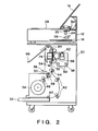
- Fig. 2 is a cross sectional view which schematically illustrates the internal structure of the copying machine 10 shown in Fig. 1 when viewed from a side position.
- the reader portion 12 has an exposure lamp 22, a lens 24 and an image sensor 26 (a CCD sensor according to this embodiment), which is capable of full-color reading a line image, to read the image of an original document placed on an original document retainer glass 28, a projected image formed by a projector or the image of a sheet-like original document fed by a sheet feeding mechanism 30.
- an exposure lamp 22 a lens 24 and an image sensor 26 (a CCD sensor according to this embodiment), which is capable of full-color reading a line image, to read the image of an original document placed on an original document retainer glass 28, a projected image formed by a projector or the image of a sheet-like original document fed by a sheet feeding mechanism 30.
- image information thus read by the reader portion 12 is subjected to a variety of processes in the reader portion 12 and the controller portion 14. Then, information, which has been read and processed, is supplied to the printer portion 20 in which it is recorded to the recording paper.
- the recording paper is selectively supplied in this way that small regular size (A4 to A3 size according to this embodiment) cut-sheets accommodated in a paper feeding cassette 32 or a roll paper 34 for recording information to large size (A2 to A1 size according to this embodiment) recording paper is selectively supplied.
- the paper feeding operation is commenced in response to a command to start printing supplied from the controller portion 14.
- the recording paper is conveyed to a position, at which first paper feeding rollers 44 are located, through the following passage.
- the recording paper can be supplied manually (supplied from an outside position of the apparatus) by sequentially supplying the same through a manual feeding portion 36 along a cover for the paper feeding portion.
- a pickup roller 40 is brought into a position on the top surface of an end portion of the recording paper set in the paper feeding cassette 32, the pickup roller 40 being used to sequentially pick up the cut-sheets from the paper feeding cassette 32. Therefore, when the pickup roller 40 is rotated, the recording paper placed at the uppermost position in the paper feeding cassette 32 is picked up and is fed to cut paper feeding rollers 42. Then, the recording paper is conveyed to the first paper feeding rollers 44 by the cut-sheet feeding rollers 42.
- the roll paper 34 In a case of the roll paper 34, it is continuously fed by the action of roll paper feeding rollers 46 and is cut to have a regular length, the cut-sheet being then conveyed to the position at which the aforesaid first paper feeding rollers 44 are located.
- the recording paper In a case where the recording paper is manually fed through the manual feeding port 36, the recording paper, which has been fed manually, is conveyed to the first paper feeding rollers 44 by manual feeding rollers 50.
- the pickup rollers 40, the cut-sheet feeding rollers 42, the roll paper feeding rollers 46, the first paper feeding rollers 44 and the manual feeding rollers 50 are driven by a paper feeding motor (a DC servo motor according to this embodiment and omitted from illustration) in such a manner that their rotations can be turned on/off by the actions of electromagnetic clutches respectively provided for the aforesaid rollers.
- a paper feeding motor a DC servo motor according to this embodiment and omitted from illustration
- the recording paper thus selected and fed through either of the aforesaid paper feeding passages is conveyed to the first paper feeding rollers 44.
- a paper loop of the recording paper is formed by a predetermined quantity and the first paper feeding rollers 44 are turned on to rotate Then, second paper feeding rollers 52 convey the recording paper.
- the recording paper is slackened to form a buffer between the first paper feeding rollers 44 and the second paper feeding rollers 52 by slackening the recording paper by a predetermined quantity in order to accurately feed the recording paper between paper feeding rollers 64 disposed above a recording head 56 and the second paper feeding rollers 52 disposed below the same.
- a buffer quantity detection sensor 54 is disposed adjacent to the position at which the buffer is formed. Since the buffer of the recording paper is always formed during its conveyance, the load which acts on the paper feeding rollers 64 and the second paper feeding rollers 52 when large size recording paper is conveyed can be reduced, so that an accurate paper feeding operation can be performed.
- a scanning carriage 58 on which the recording head 56 is mounted, is reciprocated by a scanning motor 62 on a carriage rail 60 in a direction perpendicularly to the surface of the accompanying drawing sheet and thereby scanning of the recording paper in the main scanning direction is performed.
- a scanning carriage 58 on which the recording head 56 is mounted, is reciprocated by a scanning motor 62 on a carriage rail 60 in a direction perpendicularly to the surface of the accompanying drawing sheet and thereby scanning of the recording paper in the main scanning direction is performed.
- a sub-scanning directional feeding operation in which the recording paper is fed by a predetermined quantity by the paper feeding rollers 64, is performed in the returning scanning operation.
- the quantity of feeding in the sub-scanning direction is defined as a "constant quantity of movement" to be described later and is set to a length which corresponds to the width of the recording head 56 in the sub-scanning direction, that is a length which corresponds to the width of a suction hole (omitted from illustration) formed in a platen 74 at a position at which it confronts the recording head 56.
- the aforesaid suction hole acts to bring the recording paper into contact with the platen 74 in a hermetical manner.
- a predetermined quantity of the buffer is always maintained while detecting the quantity of the buffer by the buffer quantity detection sensor 54.
- the recording paper on which information has been printed is discharged onto a paper discharge tray 66.
- a paper discharge tray 66 The recording paper on which information has been printed is discharged onto a paper discharge tray 66.
- Fig. 3 illustrates the structure of a portion in the vicinity of the scanning carriage 58 according to the first embodiment.
- reference numeral 68 represents a paper feeding motor serving as a driving power source for intermittently feeding the recording paper 35 in the sub-scanning direction.
- the quantity of the rotation of the paper feeding motor 68 can be changed to an arbitrary value so as to drive the second paper feeding rollers 52 via the paper feeding rollers and a clutch 70 for the second paper feeding rollers 52.
- the scanning motor 62 serves as the driving power source for reciprocating the scanning carriage 58 via a scanning belt 72 in the main scanning direction designated by arrows A and B. Since the paper feeding operation must be accurately controlled in this embodiment while establishing an arbitrary quantity of feeding, the paper feeding motor 68 and the scanning motor 62 are formed by pulse motors.
- a paper retaining member (omitted from illustration) is disposed at a position at which it confronts the lower end portion of the platen 74.
- the paper retaining member secures the recording paper 35 to the platen 74 during the scanning operation performed by the scanning carriage 58 in order to prevent the deviation of the recording paper 35 such as an undesirable movement.
- the clutch 70 for the second paper feeding rollers 52 and the paper feeding motor 68 are respectively turned on.
- the leading portion of the recording paper 35 is conveyed on the platen 74 until it is held by the pair of the paper feeding rollers 64.
- the platen 74 has a paper detection sensor 76 disposed thereon.
- the recording paper 35 conveyed on the platen 74 is detected by the paper detection sensor 76. Information obtained by the paper detection sensor 76 is utilized to control the position and to prevent a jam and the like.
- the clutch 70 for the second paper feeding rollers 52 and the paper feeding motor 68 are respectively turned off.
- the pressure of the space in the platen 74 is lowered to a negative level by the commencement of the action of the suction motor (omitted from illustration), so that a suction operation is commence .
- the recording paper 35 is brought into contact with the surface of the platen in a hermetical manner.
- the aforesaid paper retaining member secures the recording paper 35 to the platen 74.
- the scanning carriage 58 Prior to performing the operation of printing an image onto the recording paper 35, the scanning carriage 58 is moved to a position at which a home position sensor 78 is disposed, so that the forward scanning operation is performed in the direction designated by the arrow A.
- ink for cyan (C), that for magenta (M), that for yellow (Y) and that for black (BK) are respectively discharged from recording heads 56a, 56b, 56c and 56d from predetermined positions, so that an image is recorded (printed).
- the direction of the rotation of the scanning motor 62 is reversed to move the scanning carriage 58 in the reverse direction, that is in the direction designated by the arrow B to commence the returning directional scanning operation.
- the scanning motor 62 is rotated reversely until the scanning carriage 58 returns to the position at which the home position sensor 78 is located.
- the rotation of the paper feeding motor 68 is commenced to rotate the paper feeding rollers 64, so that the paper feeding operation by a length (the width of one recording head) recorded by the recording heads 56a, 56b, 56c and 56d in a sub-scanning direction designated by an arrow C is performed.
- the quantity of feeding the recording paper that is the quantity of the movement in the sub-scanning direction is not limited to a constant quantity of the aforesaid movement of the width of one recording head but it may be set to the quantity of the one-way movement defined by the final line width.
- the recording head 56 is an ink jet nozzle unit formed by assembling 256 nozzles for each Y, M, C and BK.
- an operation of recovering the recording head 56 is performed.
- the aforesaid recovery operation is performed to stabilize the recording operation by preventing irregular discharge at the time of the start take place due to change in the viscosity of ink left in the nozzles in the recording head 56.
- pressure is applied to each nozzle in the recording head 56 according to previously programmed conditions such as the time in which the recording paper is fed, the temperature in the apparatus and the time at which the discharge is commenced and the like to perform an idle discharge of ink from each nozzle.
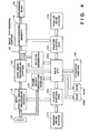
- reference numeral 100 represents a main CPU which controls the overall operation of the apparatus and to which the following units are connected: a printer control CPU 102 for controlling the operation of the printer, a reader control CPU 104 for controlling the reading operation, a main image processing portion 106 for displaying an image, an operation portion 108 serving as an input portion used by an operator, a paper money detection portion 120 for detecting whether or not the image of paper money is present in the original document and a pattern generator 122 for generating an image signal denoting the manufacturer's serial number of this apparatus.
- the main CPU 100 is also connected to a ROM 100a which stores a program or the like according to its flow chart shown in Fig. 5 and a RAM 100b for use as a work area in which a variety of programs are executed.
- the printer control CPU 102 and the reader control CPU 104 respectively control the printer portion and the reader portion and are set as slaves with respect to the main CPU 100 serving as a master.
- the aforesaid main image processing portion 106 performs edge highlight smoothing, masking, black extraction and trimming operations and the like and binary-codes the image signal by making a comparison with the slice level.
- a synchronizing memory 110 is connected to the printer control CPU 102 and, via an image synthesizing portion 124, to the main image processing portion 106.
- the synchronizing memory 110 performs an operation of absorbing scattering of the input operation time and an operation of correcting the delays taken place due to the mechanical configuration of the aforesaid recording heads.
- the output of the synchronizing memory 110 is connected to the recording head 56.
- the printer control CPU 102 is connected to a printer portion drive system 114 for controlling the input operation to the printer portion.
- the reader control CPU 104 is connected to an input system image processing portion 116 for performing correction processes such as a shading correction, a color correction and a ⁇ correction operations required for the reading system and a reader portion drive system 118 for controlling the input to the reader portion.
- the CCD line sensor 26 is connected to the input system image processing portion 116 which is connected to the main image processing portion 106.
- the paper money detection portion 120 is connected to the CCD line sensor 26 and the main CPU 100 so as to discriminate whether or not paper money or the like is included in the original document in response to a multivalue image signal for each color supplied from the CCD line sensor 26. If a fact that paper money is included in the original document is discriminated by the paper money detection portion 120, a routine of recording the manufacturer's serial number is commenced to start the pattern generator 122. The method of discrimination is later mentioned with respect to Fig. 9.
- the pattern generator 122 is connected to the main CPU 100 and the image synthesizing portion 124 to generate the manufacturer's serial number recorded on the ROM 100a in response to a command issued from the main CPU 100 so as to output it to the image synthesizing portion 124.
- the image synthesizing portion 124 is connected to the main image processing portion 106, the pattern generator 122 and the synchronizing memory 110 so as to synthesize the binary-coded image signal supplied from the main image processing portion 106 and a signal supplied from the pattern generator 122, the synthesized signal being then outputted to the synchronizing memory 110.
- the reader portion 12 is formed by the main CPU 100, the reader control CPU 104, the main image processing portion 106, the operation portion 108, the input system image processing portion 116, the paper money detection portion 120, the pattern generator 122, the reader portion drive system 118 and the CCD line sensor 26 serving as the image sensor.
- the printer portion 20 is formed by the printer control CPU 102, the synchronizing memory 110, the recording head 56 and the printer portion drive system 114.
- step (hereinafter called "S") 51 a signal denoting the manufacturer's serial number for one scan is generated so as to be synthesized with the binary signal generated by the main image processing portion 106.
- next step S52 a discrimination is made whether or not the copying operation has been completed. If the copying operation is being executed, the flow proceeds to S51. If the copying operation has been completed, the manufacturer's serial number recording routine is completed here.
- Fig. 6 illustrates an example of an operation of recording the manufacturer's serial number according to the first embodiment.
- Fig. 6 illustrates an example in which manufacturer's serial number "3851314" is recorded. It is premised that the length of the short side of paper money, which is the specific original document, is longer than any one of the marginal lengths J, K and L in the main scanning direction and the sub-scanning direction when the manufacturer's serial number is recorded. As a result, even if the image of paper money is formed on the recording paper, the manufacturer's serial number can be read from the image of the paper money formed.
- the manufacturer's serial number is printed and recorded with a yellow component because it cannot easily be recognized by human eyes.
- the color is not limited to this and it may, of course, be half tone color or may be formed by multi-color printing.
- a manufacturer's serial number signal denoting the manufacturer's serial number is generated in the pattern generator 122 in response to a signal detected by the paper money detection portion 120. Then, the manufacturer's serial number signal and the binary-coded image signal are synthesized by the image synthesizing portion 124, a synthesized image signal being used to form an image.
- the apparatus used to copy paper money can be detected from the image of the specific original document recorded on the recording paper, for example, the image of paper money. Consequently, the forgery of money paper can be prevented and it is expected that suffering of it can be prevented.
- the pattern generator continues to generate the manufacturer's serial number signal until the copying operation is completed.
- the present invention is not limited to this.
- a structure may be employed in which, if an image denoting a specific original document such as paper money is detected by the paper money detection portion, the pattern generator is commenced to synthesize the manufacturer's serial number with the binary-coded image signal and if nothing is detected, the pattern generator is stopped.
- FIG. 7 An example of printed image in the aforesaid case is shown in Fig. 7.
- reference numerals 150 and 151 represent paper money and 152 represents the recording paper.
- the paper money 150 and 151 are placed in the recording paper 152 as designated by a dashed line shown in Fig. 7.
- Symbol A denotes the length of the image in the sub-scanning direction formed by one scanning operation.
- Fig. 8 is a flow chart which illustrates the routine for recording the manufacturer's serial number according to the second embodiment of the present invention.
- the routine of recording the manufacturer's serial number is commenced and the flow of the operation performed by the main CPU 100′ proceeds to S81 shown in Fig. 8.
- next S83 whether or not the image of paper money or the like has been detected is confirmed. If the same has been detected, the flow proceeds to S81. If the same has not been detected, the routine of recording the manufacturer's serial number is completed.
- the manufacturer's serial number can be added as the pattern.
- Fig. 9 is a block diagram which illustrates the structure of the paper money detection portion 120 shown in Fig. 4.
- reference numeral 801 represents a shift register for converting image signals for C, M, Y and BK supplied in the form of a serial signal into parallel signals in this way that a timing control portion (omitted from illustration) converts the serial binary image data for C, M, Y and BK into the parallel signals.
- Reference numeral 802 represents a binary-to-multivalue conversion portion for converting the binary image data, which has been converted into the parallel signal by the shift register 801, into the multivalue image data of 5 bits for each color.
- the width of the bit is determined to be 5 bits lies in that the load acting on the ensuing process in the circuit must be reduced and the specific original document must be detected reliably. Furthermore, the image data to be converted from the binary data into the multivalue data is selectively converted into the multivalue data in such a manner that one pixel for each four pixels is converted into the multivalue data. The reason for this also lies in the aforesaid requirements.
- Reference numeral 803 represents a matching lookup table (hereinafter called a "color tone matching LUT" hereinafter) which is a ROM for matching the color tones which are the characteristics of plural kinds of specific original documents.
- Reference numerals 804-1, 804-2,..., 804-8 represent color tone discriminating circuits respectively formed by similar hardware. As typically shown by the color tone discriminating circuit 804-1, each of the color tone discriminating circuit is formed by an integrator 805, a register 807 and a comparator 806 and is capable of discriminating whether or not the specific original document is present in the image data.
- Reference numeral 808 represents an OR circuit for outputting "1" as a result of a discrimination in a case where one-or more outputs from the color tone discriminating circuits 804-1 to 804-8 denote a fact that the specific original document is present. Since the contents of the register 807 are different for each discriminating circuit, comparisons with 8 types of the specific original documents can be performed simultaneously.
- Figs. 10, 11 and 12 illustrate the binary-to-multivalue conversion method.
- the supplied binary image data is subjected to the area process as shown in Fig. 10 . That is, as shown in Fig.10 a matrix of 5 pixels x 5 pixels is used to obtain the sum of the cells in which image data is present for the purpose of obtaining the density level of a subject pixel 901. Each cell has a weight coefficient at this time and therefore a value multiplied by the weight coefficient becomes data about each cell.
- density level e of the subject pixel can be obtained by the following Equation (1): where a is image data and is 1 or 0 because it is a binary image here
- Fig. 12 illustrates an example of the weight coefficient, wherein the highest density level is "61" in the decimal format and therefore all of the density levels can be expressed with the data width of 5 bits in the binary format.
- the subject pixel 1201 is converted into multivalue data, and the fifth image data is made to be the subject pixel which is converted into the multivalue data.
- the binary-to-multivalue conversion portion 802 has individual circuits for each color code C, M, Y and BK.
- the image data for C, M, Y and BK, which have been binary-to-multivalue converted by the aforesaid method are supplied to the color tone matching LUT 803 shown in Fig. 9.
- The-color tone matching LUT 802 shown in Fig. 9 is formed by a ROM and performs the matching the color tone of the supplied image data and those of plural kinds of specific original documents (for example, paper money or securities which are the subject of the prevention of forgery), the color tone being the characteristics of an image. That is, the color tone matching LUT 803 stores color tone distribution previously examined about the 8 types of specific original documents and results of discriminations made whether or not the color tones of supplied image data coincide with the color tones of the aforesaid specific original document.
- the color tone matching LUT 803 has 20-bit address lines of A0 to A19 and, in units of 5 bits, receives image data for each C, M, Y and BK converted into the multivalue data by the binary-to-multivalue conversion portion 802.
- the color tone matching LUT 803 has 8-bit (D0 to D7) data output lines to discriminate 8 types of original documents since each bit corresponds one type of the specific original document.
- Fig. 14 is a block diagram which illustrates the structure of the integrator.
- reference numerals 1301 and 1305 represent flip-flops for holding data at the timing of the first transition of a CLK signal.
- Reference numeral 1302 represents a multiplier which receives two input signals (A and B) of 8 bits and outputs an 8-bit signal (A x B/255) denoting the result of the multiplication.
- Reference numeral 1303 represents a multiplier which receives a 1-bit input signal (A) and an 8-bit input signal (B) and which outputs an 8-bit output signal (A x B) denoting the result.
- Reference numeral 1304 represents an adder which receives an 8-bit input signals (A and B) and which outputs an 8-bit signal (A + B).
- Figs. 15 and 16 illustrate an example of input and output from the integrator.
- the integrator 805 receives x i as shown in Fig. 15 and outputs y i as shown in Fig. 16 That is, an input such a dots 1401 and 1402, the level of which is substantially “0" at its surrounding portion and the level of which is “1” or an input such as a dot 1403, the level of which is substantially “1” and the level of which is “0” are considered to be noise.
- an input such as dots 1401 and 1402
- a threshold such as a level 1404 shown in Fig. 16 is provided for the register 807 shown in Fig. 16 so as to be used to binary-code the output yi from the integrator.
- the aforesaid noise can be eliminated.
- the present invention is not limited to this and is therefore embodied in an electrophotographic system, a thermosensitive system and a photographic system.
- it may be applied to a so-called bubble jet type printer having a head of a type for discharging a liquid droplet by utilizing film boiling taken place by heat energy.
- the present invention is not limited to the color copying machine and it may be utilized in a monochrome digital copying machine for converting an image signal into a binary signal.
- the input is not limited to that made from the scanner as is done in the aforesaid copying machine.
- the present invention can be applied to a system for printing by processing an image supplied from external equipment via an I/F or a system in which an image supplied from a communication apparatus is processed so as to be printed.
- data to be generated by the pattern generator is not limited to the manufacturer's serial number, and any code such as the bar code may therefore by utilized if the apparatus can be specified according to the copied paper money.
- the data is not also limited to the code for identifying the apparatus, and therefore any code denoting the location of the apparatus, date, the name of an owner or user may be used.
- any color can be employed to record it.
- the present invention is not limited to the paper money as the specific original document. It can therefore be applied to any document such as securities and variable document, the copy of which must be inhibited.
- the present invention can be applied to any postcard and document as well the document, the copy of which must be inhibited.
- the present invention may be applied to a system composed of a plurality of apparatuses or a system composed of one apparatus.
- the present invention may, of course, be applied to a case which is established by supplying a program to the system or an apparatus.
- yellow is used as the added color
- the present invention is not limited to this.
- a quiet color such as yellow green or gray or a color having a high brightness such as purple or light green may be employed.
- the original document may be that inputted by a still video camera or a video camera and the original document may be that processed according to the computer graphics.
Landscapes
- Engineering & Computer Science (AREA)
- Multimedia (AREA)
- Signal Processing (AREA)
- Computer Security & Cryptography (AREA)
- Computer Vision & Pattern Recognition (AREA)
- Physics & Mathematics (AREA)
- General Physics & Mathematics (AREA)
- Theoretical Computer Science (AREA)
- Facsimile Image Signal Circuits (AREA)
- Accessory Devices And Overall Control Thereof (AREA)
- Editing Of Facsimile Originals (AREA)
- Image Processing (AREA)
Claims (24)
- Bilderzeugungsgerät (10) miteiner Eingabeeinrichtung (26) zum Empfang von ein eingegebenes Bild definierenden Bilddaten,einer Verarbeitungseinrichtung (100; 106; 116) zur Verarbeitung der empfangenen Bilddaten, damit Ausgabebilddaten erzeugt werden undeiner Druckeinrichtung (20; 56) zur Verwendung der Ausgabebilddaten zum Drucken eines das eingegebene Bild wiedergebenden sichtbaren Bildes,dadurch gekennzeichnet, daßdie Ausgabebilddaten das sichtbare Bild als binäres Bild definieren,das Bilderzeugungsgerät eine Speichereinrichtung (100a) aufweist, die das Bilderzeugungsgerät identifizierende Identifikationsinformationen speichert, wobei die Identifikationsinformationen durch Benutzer nicht-überschreibbar gespeichert sind, unddas Bilderzeugungsgerät der Identifikationsinformationen auf dem gedruckten, sichtbaren Bild in einer mit dem normalen, bloßen, menschlichen Auge schwer zu unterscheidenden Weise darstellt.
- Bildverarbeitungsgerät (100-110; 114-124) miteiner Eingabeeinrichtung (116) zum Empfang von ein eingegebenes Bild definierenden Bilddaten undeiner Verarbeitungseinrichtung (106; 116) zur Verarbeitung der empfangenen Bilddaten, damit Ausgabebilddaten erzeugt werden, die ein das eingegebene Bild wiedergebendes sichtbares Bild definieren,dadurch gekennzeichnet, daßdie Ausgabebilddaten das sichtbare Bild als binäres Bild definieren unddas Bildverarbeitungsgerät eine Speichereinrichtung (100a) aufweist, die das Bilderzeugungsgerät identifizierende Identifikationsinformationen speichert, wobei die Identifikationsinformationen durch Benutzer nicht-überschreibbar gespeichert sind, undeine Zusammenfügungseinrichtung (124) zur Zusammenfügung von die Identifikationsinformationen darstellenden Identifikationsdaten mit den Ausgabebilddaten aufweist, so daß eine sichtbare Wiedergabe des eingegebenen Bildes unter Verwendung der zusammengefügten Ausgabebilddaten eine Darstellung der Identifikationsinformationen in einer, mit dem normalen, bloßen, menschlichen Auge schwer zu unterscheidenden Weise enthält.
- Gerät nach Anspruch 1,
dadurch gekennzeichnet, daßdas eingegebene Bild ein vielfarbiges Bild ist,die Druckeinrichtung einzelne sichtbare Farbkomponenten druckt, damit das vielfarbige eingegebene Bild wiedergegeben wird, unddie Identifikationsinformationen in einer oder mehreren der gedruckten, sichtbaren Farbkomponenten dargestellt werden. - Gerät nach Anspruch 2,
dadurch gekennzeichnet, daß
das eingegebene Bild ein vielfarbiges Bild ist und die Ausgabebilddaten einzelne, sichtbare Farbkomponenten aufweisen. - Gerät nach Anspruch 3 oder 4,
dadurch gekennzeichnet, daß
die einzelnen Farbkomponenten Bilder in Magenta, Zyan, Gelb und Schwarz aufweisen und die Identifikationsinformationen in der gedruckten gelben Farbkomponente dargestellt werden. - Gerät nach einem der vorangehenden Ansprüche,
gekennzeichnet durcheine Speichereinrichtung (120) zur Speicherung einer Bezugsdateneigenschaft von zumindest einem vorbestimmten Bezugsbild undeine Vergleichseinrichtung (100; 120) zur Verwendung der empfangenen Bilddaten und der gespeicherten Bezugsdaten zur Bestimmung, ob das eingegebene Bild dem Bezugsbild entspricht,wobei die Identifikationsinformationen auf dem gedruckten, sichtbaren Bild in Abhängigkeit von der Bestimmung dargestellt sind. - Gerät nach Anspruch 6,
dadurch gekennzeichnet, daß
die Darstellung der Identifikationsinformationen lediglich an Stellen (150; 151) auf dem gedruckten, sichtbaren Bild erscheint, an denen die Entsprechung des Bildes mit dem Bezugsbild bestimmt wird. - Gerät nach einem der vorangehenden Ansprüche,
dadurch gekennzeichnet, daß
die das eingegebene Bild definierenden Bilddaten mehrwertige Bilddaten sind und das Gerät eine Binärkodiereinrichtung (106) zur Umwandlung der mehrwertigen Bilddaten in zweiwertige Bilddaten aufweist. - Gerät nach einem der vorangehenden Ansprüche,
dadurch gekennzeichnet, daß
die Identifikationsinformationen eine Seriennummer des Geräts aufweisen. - Gerät nach einem der vorangehenden Ansprüche,
dadurch gekennzeichnet, daß
die Darstellung der Identifikationsinformationen auf dem gedruckten, sichtbaren Bild in einem vorbestimmten Intervall wiederholt auftritt. - Gerät nach einem der vorangehenden Ansprüche,
dadurch gekennzeichnet, daß
die Eingabeeinrichtung eine Bildleseeinrichtung mit einem CCD-Sensor (26) aufweist. - Gerät nach Anspruch 1 oder Anspruch 3,
dadurch gekennzeichnet, daß
die Druckeinrichtung einen Bläschenstrahldrucker aufweist. - Gerät nach Anspruch 12, wenn dieser von Anspruch 3 abhängig ist,
dadurch gekennzeichnet, daß
die Druckeinrichtung ein Bild unter Verwendung einer Vielzahl von Düsen für jede Farbkomponente aufzeichnet. - Verfahren zum Betrieb eines Bilderzeugungsgeräts zur Erzeugung eines Wiedergabebildes, mit den Schritten:Empfangen von ein eingegebenes Bild definierenden Bilddaten,Verarbeiten der empfangenen Bilddaten, damit Ausgabebilddaten erzeugt werden, undVerwenden der Ausgabebilddaten zum Drucken eines das eingegebene Bild wiedergebenden sichtbaren Bildes,dadurch gekennzeichnet, daß
die Ausgabebilddaten das sichtbare Bild als binäres Bild definieren, und dadurch, daß das Verfahren weiterhin die Schritte aufweist:Speichern der das Bilderzeugungsgerät identifizierenden Identifikationsinformationen, wobei die Identifikationsinformationen durch Benutzer nicht-überschreibbar gespeichert sind, undDarstellen der Identifikationsinformationen auf dem gedruckten, sichtbaren Bild in einer mit dem normalen, bloßen, menschlichen Auge schwer zu unterscheidenden Weise. - Verfahren zum Betrieb eines Bildverarbeitungsgeräts mit den Schritten:Empfangen von ein eingegebenes Bild definierenden Bilddaten undVerarbeiten der empfangenen Bilddaten, damit Ausgabebilddaten erzeugt werden, die ein das eingegebene Bild wiedergebendes sichtbares Bild definieren,dadurch gekennzeichnet, daß
die Ausgabebilddaten das sichtbare Bild als binäres Bild definieren, und dadurch, daß das Verfahren die folgenden Schritte aufweist:Speichern der das Bildverarbeitungsgerät identifizierenden Identifikationsinformationen, wobei die Identifikationsinformationen durch Benutzer nicht-überschreibbar gespeichert sind, undZusammenfügen von die Identifikationsinformationen darstellenden Identifikationsdaten mit den Ausgabebilddaten, so daß eine sichtbare Wiedergabe des eingegebenen Bildes unter Verwendung der zusammengefügten Ausgabebilddaten eine Darstellung der Identifikationsinformationen in einer, mit dem normalen, bloßen, menschlichen Auge schwer zu unterscheidenden Weise enthält. - Verfahren nach Anspruch 14,
dadurch gekennzeichnet, daßdas eingegebene Bild ein vielfarbiges Bild ist, einzelne sichtbare Farbkomponenten derart gedruckt werden, daß das vielfarbige eingegebene Bild wiedergegeben wird, unddie Identifikationsinformationen in einer oder mehreren der gedruckten, sichtbaren Farbkomponenten dargestellt werden. - Verfahren nach Anspruch 15,
dadurch gekennzeichnet, daß
das eingegebene Bild ein vielfarbiges Bild ist und die Ausgabebilddaten einzelne, sichtbare Farbkomponenten aufweisen. - Verfahren nach Anspruch 16 oder 17,
dadurch gekennzeichnet, daß
die einzelnen Farbkomponenten Bilder in Magenta, Zyan, Gelb und Schwarz aufweisen und die Identifikationsinformationen in der gedruckten gelben Farbkomponente dargestellt werden. - Verfahren nach einem der Ansprüche 14 bis 18,
gekennzeichnet durch die Schritte:Speichern einer Bezugsdateneigenschaft von zumindest einem vorbestimmten Bezugsbild undVerwenden der empfangenen Bilddaten und der gespeicherten Bezugsdaten zur Bestimmung, ob das eingegebene Bild dem Bezugsbild entspricht,wobei die Identifikationsinformationen auf dem gedruckten, sichtbaren Bild in Abhängigkeit von der Bestimmung dargestellt sind. - Verfahren nach Anspruch 19,
dadurch gekennzeichnet, daß
die Darstellung der Identifikationsinformationen lediglich an Stellen auf dem gedruckten, sichtbaren Bild erscheint, an denen die Entsprechung des Bildes mit dem Bezugsbild bestimmt wird. - Verfahren nach einem der Ansprüche 14 bis 20,
dadurch gekennzeichnet, daß
die das eingegebene Bild definierenden Bilddaten mehrwertige Bilddaten sind und das Verfahren den Schritt des Umwandelns der mehrwertigen Bilddaten in zweiwertige Bilddaten aufweist. - Verfahren nach einem der Ansprüche 14 bis 21,
dadurch gekennzeichnet, daß
die Identifikationsinformationen eine Seriennummer des Geräts aufweisen. - Verfahren nach einem der Ansprüche 14 bis 22,
dadurch gekennzeichnet, daß
die Darstellung der Identifikationsinformationen auf dem gedruckten, sichtbaren Bild in einem vorbestimmten Intervall wiederholt auftritt. - Digitale Farbkopiervorrichtung mit einem Gerät nach einem der Ansprüche 1 bis 13.
Applications Claiming Priority (6)
| Application Number | Priority Date | Filing Date | Title |
|---|---|---|---|
| JP06690391A JP3298900B2 (ja) | 1991-03-29 | 1991-03-29 | 画像処理装置およびその方法 |
| JP66903/91 | 1991-03-29 | ||
| JP3245387A JPH0583548A (ja) | 1991-09-25 | 1991-09-25 | 画像形成装置 |
| JP245387/91 | 1991-09-25 | ||
| JP252217/91 | 1991-09-30 | ||
| JP3252217A JPH0591294A (ja) | 1991-09-30 | 1991-09-30 | 画像処理装置 |
Publications (3)
| Publication Number | Publication Date |
|---|---|
| EP0506479A2 EP0506479A2 (de) | 1992-09-30 |
| EP0506479A3 EP0506479A3 (en) | 1993-04-28 |
| EP0506479B1 true EP0506479B1 (de) | 1997-02-12 |
Family
ID=27299303
Family Applications (1)
| Application Number | Title | Priority Date | Filing Date |
|---|---|---|---|
| EP92302753A Expired - Lifetime EP0506479B1 (de) | 1991-03-29 | 1992-03-27 | Bildverarbeitungsgerät |
Country Status (4)
| Country | Link |
|---|---|
| US (2) | US5621503A (de) |
| EP (1) | EP0506479B1 (de) |
| CA (1) | CA2064260C (de) |
| DE (1) | DE69217403T2 (de) |
Families Citing this family (46)
| Publication number | Priority date | Publication date | Assignee | Title |
|---|---|---|---|---|
| SG71841A1 (en) | 1991-03-29 | 2000-04-18 | Canon Kk | Image processing apparatus and copying machine |
| JP3260810B2 (ja) * | 1992-03-31 | 2002-02-25 | キヤノン株式会社 | 画像処理装置及びその方法 |
| US6301369B2 (en) | 1992-07-31 | 2001-10-09 | Digimarc Corporation | Image marking to permit later identification |
| US5721788A (en) | 1992-07-31 | 1998-02-24 | Corbis Corporation | Method and system for digital image signatures |
| WO1994003996A1 (fr) * | 1992-08-05 | 1994-02-17 | Ricoh Company, Ltd. | Appareil de formation d'image |
| CA2106708C (en) * | 1992-09-25 | 2000-01-25 | Nobuatsu Sasanuma | Image processing apparatus and method thereof |
| US6421145B1 (en) * | 1992-09-28 | 2002-07-16 | Canon Kabushiki Kaisha | Image processing apparatus and method using image information and additional information or an additional pattern added thereto or superposed thereon |
| EP0609008B1 (de) | 1993-01-19 | 2001-06-20 | Canon Kabushiki Kaisha | Bildverarbeitungsvorrichtung und -verfahren |
| US6983051B1 (en) * | 1993-11-18 | 2006-01-03 | Digimarc Corporation | Methods for audio watermarking and decoding |
| US5748763A (en) | 1993-11-18 | 1998-05-05 | Digimarc Corporation | Image steganography system featuring perceptually adaptive and globally scalable signal embedding |
| US5822436A (en) | 1996-04-25 | 1998-10-13 | Digimarc Corporation | Photographic products and methods employing embedded information |
| US7676059B2 (en) * | 1994-10-21 | 2010-03-09 | Digimarc Corporation | Video steganography or encoding |
| US6449377B1 (en) | 1995-05-08 | 2002-09-10 | Digimarc Corporation | Methods and systems for watermark processing of line art images |
| US5768426A (en) | 1993-11-18 | 1998-06-16 | Digimarc Corporation | Graphics processing system employing embedded code signals |
| US7171016B1 (en) | 1993-11-18 | 2007-01-30 | Digimarc Corporation | Method for monitoring internet dissemination of image, video and/or audio files |
| JP3566334B2 (ja) * | 1994-03-25 | 2004-09-15 | キヤノン株式会社 | 画像処理装置およびその方法 |
| JP3224480B2 (ja) * | 1994-09-30 | 2001-10-29 | キヤノン株式会社 | カラー画像処理装置 |
| US6560349B1 (en) | 1994-10-21 | 2003-05-06 | Digimarc Corporation | Audio monitoring using steganographic information |
| US5752152A (en) * | 1996-02-08 | 1998-05-12 | Eastman Kodak Company | Copy restrictive system |
| WO1997036417A1 (en) * | 1996-03-27 | 1997-10-02 | Omron Corporation | Method and device for recognizing image, and copying machine and printer using them |
| US5754933A (en) * | 1996-07-19 | 1998-05-19 | Invisible Images, Inc. | Method for preserving research records generated by computer |
| US6064517A (en) | 1996-07-22 | 2000-05-16 | Kla-Tencor Corporation | High NA system for multiple mode imaging |
| JP3934714B2 (ja) * | 1996-10-31 | 2007-06-20 | 日本金銭機械株式会社 | 紙幣鑑別装置 |
| JP3781850B2 (ja) * | 1997-01-21 | 2006-05-31 | シャープ株式会社 | 画像形成システム |
| JP3418308B2 (ja) * | 1997-05-01 | 2003-06-23 | 株式会社リコー | 画像形成装置 |
| US6320675B1 (en) * | 1997-07-15 | 2001-11-20 | Canon Kabushiki Kaisha | Image processing apparatus and method and storage medium |
| US7028899B2 (en) * | 1999-06-07 | 2006-04-18 | Metrologic Instruments, Inc. | Method of speckle-noise pattern reduction and apparatus therefore based on reducing the temporal-coherence of the planar laser illumination beam before it illuminates the target object by applying temporal phase modulation techniques during the transmission of the plib towards the target |
| JP3731316B2 (ja) * | 1997-10-02 | 2006-01-05 | コニカミノルタビジネステクノロジーズ株式会社 | 画像読取り装置 |
| US8290202B2 (en) | 1998-11-03 | 2012-10-16 | Digimarc Corporation | Methods utilizing steganography |
| JP2000148997A (ja) * | 1998-11-13 | 2000-05-30 | Minolta Co Ltd | 画像処理装置 |
| FR2788399B1 (fr) * | 1999-01-08 | 2001-02-09 | Sagem | Telecopieur a identification de telecopies |
| US6522766B1 (en) | 1999-03-15 | 2003-02-18 | Seiko Epson Corporation | Watermarking with random zero-mean patches for copyright protection |
| US6556688B1 (en) | 1999-03-15 | 2003-04-29 | Seiko Epson Corporation | Watermarking with random zero-mean patches for printer tracking |
| US6209923B1 (en) | 1999-04-14 | 2001-04-03 | The Standard Register Company | Security document and authentication scheme |
| JP3636633B2 (ja) * | 1999-05-13 | 2005-04-06 | キヤノン株式会社 | 画像形成装置 |
| US6414752B1 (en) * | 1999-06-18 | 2002-07-02 | Kla-Tencor Technologies Corporation | Method and apparatus for scanning, stitching, and damping measurements of a double-sided metrology inspection tool |
| US7002710B1 (en) | 2000-04-10 | 2006-02-21 | Hewlett-Packard Development Company, L.P. | High reliability forensic color marking system |
| GB0025096D0 (en) * | 2000-10-13 | 2000-11-29 | Bank Of England | Detection of printing and coating media |
| US7072487B2 (en) * | 2001-01-26 | 2006-07-04 | Digimarc Corporation | Watermark detection using adaptive color projections |
| US6722568B2 (en) | 2001-11-20 | 2004-04-20 | Ncr Corporation | Methods and apparatus for detection and processing of supplemental bar code labels |
| US8181884B2 (en) * | 2003-11-17 | 2012-05-22 | Digimarc Corporation | Machine-readable features for objects |
| JP4262230B2 (ja) * | 2005-09-29 | 2009-05-13 | 株式会社沖データ | 画像形成装置、画像形成システムおよび画像形成方法 |
| KR101297623B1 (ko) * | 2006-05-18 | 2013-08-20 | 톰슨 라이센싱 | 데이터 은닉 기술 |
| JP4343968B2 (ja) * | 2007-03-13 | 2009-10-14 | キヤノン株式会社 | 画像形成装置及び方法 |
| US8737901B2 (en) * | 2008-05-01 | 2014-05-27 | Xerox Corporation | Counterfeit deterrence using full width array scans |
| USD666514S1 (en) * | 2011-04-08 | 2012-09-04 | Dri-Mark Products | Three way desktop UV counterfeit detector |
Family Cites Families (16)
| Publication number | Priority date | Publication date | Assignee | Title |
|---|---|---|---|---|
| JPS5459936A (en) * | 1977-10-03 | 1979-05-15 | Canon Inc | Recording method and device therefor |
| CA1127227A (en) * | 1977-10-03 | 1982-07-06 | Ichiro Endo | Liquid jet recording process and apparatus therefor |
| JPS54153512A (en) * | 1978-05-25 | 1979-12-03 | Ricoh Co Ltd | Addition system for identifying information |
| DE2936667A1 (de) * | 1978-09-12 | 1980-03-20 | Canon Kk | Kopiergeraet |
| US4908873A (en) * | 1983-05-13 | 1990-03-13 | Philibert Alex C | Document reproduction security system |
| US4723149A (en) * | 1985-05-08 | 1988-02-02 | Kabushiki Kaisha Toshiba | Image forming apparatus having a function for checking to copy a secret document |
| US4989042A (en) * | 1987-02-26 | 1991-01-29 | Canon Kabushiki Kaisha | Image synthesizing apparatus |
| EP0297242B1 (de) * | 1987-06-30 | 1994-07-06 | Kabushiki Kaisha Toshiba | System und Verfahren zur Aufnahme/Wiedergabe mit Aufnahmebeschränkungsfunktion |
| DE3889283T2 (de) * | 1987-10-16 | 1994-09-01 | Canon Kk | Gerät zur Bildherstellung. |
| DE3810652A1 (de) * | 1988-03-29 | 1989-10-12 | Bernard M Jordan | Verfahren zum schutze von auf einen traeger aufgebrachter information und informationstraeger |
| ES2093767T3 (es) * | 1988-05-13 | 1997-01-01 | Canon Kk | Aparato para el proceso de imagenes. |
| US5321470A (en) * | 1988-05-13 | 1994-06-14 | Canon Kabushiki Kaisha | Apparatus with anti-forgery provision |
| JPH02114287A (ja) * | 1988-10-25 | 1990-04-26 | Canon Inc | 画像形成装置 |
| SG120852A1 (en) * | 1989-02-10 | 2006-04-26 | Canon Kk | Apparatus for image reading or processing |
| US5227871A (en) * | 1990-11-30 | 1993-07-13 | Canon Kabushiki Kaisha | Image processing apparatus capable of discriminating a predetermined image |
| US5430525A (en) * | 1990-11-30 | 1995-07-04 | Canon Kabushiki Kaisha | Image processing apparatus |
-
1992
- 1992-03-27 EP EP92302753A patent/EP0506479B1/de not_active Expired - Lifetime
- 1992-03-27 DE DE69217403T patent/DE69217403T2/de not_active Expired - Lifetime
- 1992-03-27 CA CA002064260A patent/CA2064260C/en not_active Expired - Lifetime
-
1994
- 1994-03-14 US US08/209,373 patent/US5621503A/en not_active Expired - Lifetime
-
1997
- 1997-01-08 US US08/780,358 patent/US5790932A/en not_active Expired - Lifetime
Also Published As
| Publication number | Publication date |
|---|---|
| CA2064260A1 (en) | 1992-09-30 |
| DE69217403D1 (de) | 1997-03-27 |
| US5621503A (en) | 1997-04-15 |
| EP0506479A3 (en) | 1993-04-28 |
| CA2064260C (en) | 1999-12-14 |
| DE69217403T2 (de) | 1997-07-10 |
| US5790932A (en) | 1998-08-04 |
| EP0506479A2 (de) | 1992-09-30 |
Similar Documents
| Publication | Publication Date | Title |
|---|---|---|
| EP0506479B1 (de) | Bildverarbeitungsgerät | |
| US5363454A (en) | Image processing apparatus | |
| US6831683B2 (en) | Methods and apparatus for print control of moving a position of a non-print area | |
| US6876460B2 (en) | Image processing apparatus, image processing method and storage medium | |
| CN104339884B (zh) | 打印装置、信息处理装置以及打印装置控制方法 | |
| US8711433B2 (en) | Image forming apparatus and method for making density correction in a low resolution image based on edge determination | |
| US5790165A (en) | Image processing apparatus and providing controlling addition of predetermined data in a border portion | |
| JPH0887206A (ja) | 処理中制御方法及びドキュメントプリント方法 | |
| JP3144676B2 (ja) | 画像形成用制御装置及び画像形成装置 | |
| JP2967988B2 (ja) | 画像記録装置 | |
| JP2005205685A (ja) | 画像処理装置及び画像処理方法 | |
| JP3320113B2 (ja) | 画像形成装置 | |
| JP4456850B2 (ja) | 画像形成装置 | |
| JP3298900B2 (ja) | 画像処理装置およびその方法 | |
| JPH0583548A (ja) | 画像形成装置 | |
| JP2000103141A (ja) | 画像記録装置 | |
| JPH0591294A (ja) | 画像処理装置 | |
| JP2009151497A (ja) | 画像処理装置とその制御方法 | |
| JPH05284349A (ja) | 画像処理装置及び画像処理システム | |
| JP2022117830A (ja) | 画像処理装置、画像処理方法、記録装置及びプログラム | |
| JPH06113097A (ja) | 画像形成装置 | |
| JPH06113115A (ja) | 画像形成装置 | |
| JPH06113116A (ja) | 画像形成装置 | |
| JP2001026146A (ja) | 画像形成装置 | |
| JP2004142388A (ja) | プリントシステム及びプリンタ |
Legal Events
| Date | Code | Title | Description |
|---|---|---|---|
| PUAI | Public reference made under article 153(3) epc to a published international application that has entered the european phase |
Free format text: ORIGINAL CODE: 0009012 |
|
| AK | Designated contracting states |
Kind code of ref document: A2 Designated state(s): DE FR GB IT NL |
|
| PUAL | Search report despatched |
Free format text: ORIGINAL CODE: 0009013 |
|
| AK | Designated contracting states |
Kind code of ref document: A3 Designated state(s): DE FR GB IT NL |
|
| 17P | Request for examination filed |
Effective date: 19930716 |
|
| 17Q | First examination report despatched |
Effective date: 19941123 |
|
| GRAG | Despatch of communication of intention to grant |
Free format text: ORIGINAL CODE: EPIDOS AGRA |
|
| GRAH | Despatch of communication of intention to grant a patent |
Free format text: ORIGINAL CODE: EPIDOS IGRA |
|
| GRAH | Despatch of communication of intention to grant a patent |
Free format text: ORIGINAL CODE: EPIDOS IGRA |
|
| GRAA | (expected) grant |
Free format text: ORIGINAL CODE: 0009210 |
|
| AK | Designated contracting states |
Kind code of ref document: B1 Designated state(s): DE FR GB IT NL |
|
| ET | Fr: translation filed | ||
| REF | Corresponds to: |
Ref document number: 69217403 Country of ref document: DE Date of ref document: 19970327 |
|
| ITF | It: translation for a ep patent filed | ||
| PLBE | No opposition filed within time limit |
Free format text: ORIGINAL CODE: 0009261 |
|
| STAA | Information on the status of an ep patent application or granted ep patent |
Free format text: STATUS: NO OPPOSITION FILED WITHIN TIME LIMIT |
|
| 26N | No opposition filed | ||
| REG | Reference to a national code |
Ref country code: GB Ref legal event code: IF02 |
|
| PGFP | Annual fee paid to national office [announced via postgrant information from national office to epo] |
Ref country code: NL Payment date: 20100315 Year of fee payment: 19 Ref country code: IT Payment date: 20100329 Year of fee payment: 19 |
|
| PGFP | Annual fee paid to national office [announced via postgrant information from national office to epo] |
Ref country code: FR Payment date: 20110407 Year of fee payment: 20 Ref country code: DE Payment date: 20110331 Year of fee payment: 20 Ref country code: GB Payment date: 20110311 Year of fee payment: 20 |
|
| REG | Reference to a national code |
Ref country code: NL Ref legal event code: V1 Effective date: 20111001 |
|
| PG25 | Lapsed in a contracting state [announced via postgrant information from national office to epo] |
Ref country code: NL Free format text: LAPSE BECAUSE OF NON-PAYMENT OF DUE FEES Effective date: 20111001 |
|
| PG25 | Lapsed in a contracting state [announced via postgrant information from national office to epo] |
Ref country code: IT Free format text: LAPSE BECAUSE OF NON-PAYMENT OF DUE FEES Effective date: 20110327 |
|
| REG | Reference to a national code |
Ref country code: DE Ref legal event code: R071 Ref document number: 69217403 Country of ref document: DE |
|
| REG | Reference to a national code |
Ref country code: DE Ref legal event code: R071 Ref document number: 69217403 Country of ref document: DE |
|
| REG | Reference to a national code |
Ref country code: GB Ref legal event code: PE20 Expiry date: 20120326 |
|
| PG25 | Lapsed in a contracting state [announced via postgrant information from national office to epo] |
Ref country code: DE Free format text: LAPSE BECAUSE OF EXPIRATION OF PROTECTION Effective date: 20120328 |
|
| PG25 | Lapsed in a contracting state [announced via postgrant information from national office to epo] |
Ref country code: GB Free format text: LAPSE BECAUSE OF EXPIRATION OF PROTECTION Effective date: 20120326 |