EP0505342A2 - Reaktiver Schalldämpfer, insbesondere für Luftleitungen in Papierfabriken - Google Patents
Reaktiver Schalldämpfer, insbesondere für Luftleitungen in Papierfabriken Download PDFInfo
- Publication number
- EP0505342A2 EP0505342A2 EP92850058A EP92850058A EP0505342A2 EP 0505342 A2 EP0505342 A2 EP 0505342A2 EP 92850058 A EP92850058 A EP 92850058A EP 92850058 A EP92850058 A EP 92850058A EP 0505342 A2 EP0505342 A2 EP 0505342A2
- Authority
- EP
- European Patent Office
- Prior art keywords
- sound attenuator
- sound
- chamber
- tube
- partition wall
- Prior art date
- Legal status (The legal status is an assumption and is not a legal conclusion. Google has not performed a legal analysis and makes no representation as to the accuracy of the status listed.)
- Granted
Links
Images

Classifications
-
- G—PHYSICS
- G10—MUSICAL INSTRUMENTS; ACOUSTICS
- G10K—SOUND-PRODUCING DEVICES; METHODS OR DEVICES FOR PROTECTING AGAINST, OR FOR DAMPING, NOISE OR OTHER ACOUSTIC WAVES IN GENERAL; ACOUSTICS NOT OTHERWISE PROVIDED FOR
- G10K11/00—Methods or devices for transmitting, conducting or directing sound in general; Methods or devices for protecting against, or for damping, noise or other acoustic waves in general
- G10K11/16—Methods or devices for protecting against, or for damping, noise or other acoustic waves in general
- G10K11/172—Methods or devices for protecting against, or for damping, noise or other acoustic waves in general using resonance effects
-
- F—MECHANICAL ENGINEERING; LIGHTING; HEATING; WEAPONS; BLASTING
- F24—HEATING; RANGES; VENTILATING
- F24F—AIR-CONDITIONING; AIR-HUMIDIFICATION; VENTILATION; USE OF AIR CURRENTS FOR SCREENING
- F24F13/00—Details common to, or for air-conditioning, air-humidification, ventilation or use of air currents for screening
- F24F13/24—Means for preventing or suppressing noise
Definitions
- the invention concerns a reactive sound attenuator for air-conditioning ducts, in particular for air ducts in paper mills, said sound attenuator consisting of at least two chambers separated from one another by means of a partition wall, which partition wall is provided with an opening or with a tube placed in the direction of flow of the air flowing through the sound attenuator, the air flowing through said opening or tube out of one chamber into the other.
- Absorptive sound attenuators operate primarily at higher frequencies; the maximum of their attenuation is at a frequency of about 1000 Hz, whereas reactive sound attenuators operate most efficiently at low frequencies, and their maximum attenuation is, as a rule, tuned in a range of about 100...200 Hz.
- reactive attenuators are attenuators for low frequencies, whose operation is based on their geometric forms.
- a reactive attenuator is composed of one or several chambers or tubes, and such an attenuator causes reflection of the sound energy back towards the source of sound, or reflection of the sound energy back and forth between the chambers, whereby part of the sound energy does not pass through the attenuator.
- the prior-art reactive sound attenuator consisting of one or several chambers is called chamber resonator.
- the extent of attenuation in a chamber resonator is determined by the ratio of the cross-sectional area of the chamber to the cross-sectional area of the related duct, and the frequencies that are attenuated are determined by the length of the chamber.
- the attenuation of transmission given by Equation I is true when the largest transverse dimension of the chamber is smaller than 0.8 x wavelength (L. Beranek, Noise and Vibration Control , McGraw-Hill, 1971).
- L TL 10 log ⁇ 1 + 1/4 (m-1/m)2 sin2kl ⁇ dB wherein
- the attenuation of the chamber resonator is a periodic function of kl and receives the value 0dB when the length of the chamber is ⁇ /2, ⁇ , 3 ⁇ /2, etc.
- the maximum attenuation is obtained when the length l of the chamber is ⁇ /4, 3 ⁇ /4, 5 ⁇ /4, etc.
- the object of the invention is to provide a solution in which a complete zero attenuation in reactive attenuators is avoided.
- the sound attenuator in accordance with the invention is mainly characterized in that the main plane of said partition wall is at an acute angle in relation to the direction of flow of the air flowing through the sound attenuator.
- the main plane of the partition wall that separates the chambers in a wide-range reactive sound attenuator is placed at an acute angle, i.e. at a non-right (90°) angle in relation to the direction of flow of the air that flows through the sound attenuator.
- an acute angle i.e. at a non-right (90°) angle in relation to the direction of flow of the air that flows through the sound attenuator.
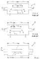
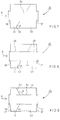
- Figure A is a schematic illustration of a prior-art tube-resonator sound attenuator.
- Figure B is a schematic illustration of a second embodiment of a prior-art tube resonator.
- Figure 1 is a schematic illustration of a tube resonator in accordance with the invention.
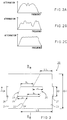
- Figures 2A to 2C illustrate the attenuations of principle in the tube resonators shown in Figs. A, B and 1.
- Figure 3 is a schematic illustration of an exemplifying embodiment of a tube resonator in accordance with the invention.
- Figures 4A to 4C are schematic illustrations of examples of cross sections B-B (Fig. 3) of a sound attenuator in accordance with the invention in the direction perpendicular to the flow direction of the air flowing through the sound attenuator.
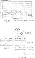
- Figures 5A to 5E show the results of a measurement of attenuation of a chamber-resonator sound attenuator in accordance with the invention as compared with the results of measurements of attenuation of prior-art chamber-resonator attenuators.
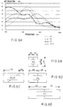
- Figures 6A to 6E show the results of a measurement of attenuation of a tube-resonator sound attenuator in accordance with the invention as compared with the results of measurements of attenuation of prior-art tube-resonator sound attenuators.
- FIG. 7 is a schematic illustration of a chamber resonator in accordance with the invention
- Figure 8 is a schematic illustration of a further exemplifying embodiment of a sound attenuator in accordance with the invention.
- Figure 9 is a schematic illustration of a second further exemplifying embodiment of a sound attenuator in accordance with the invention.
- a prior-art tube-resonator sound attenuator 10 as shown in Fig. A usually consists of two chambers 11 separated by a partition wall 12. Through the partition wall 12, a tube 13 has been installed, whose ends 16 have been dimensioned to be placed in the middle of the chambers 11 in order to obtain the best attenuation.
- the length of the chamber 11 is denoted with the reference 1
- the length of the tube 13 installed through the partition wall 12, at the side of each chamber is denoted with the reference 1/2.
- the chambers 11 are equally large.
- the chambers 14 and 15 in the tube resonator 10 are constructed, in the way shown in Fig. B and in the way known from the prior art, so that the chambers have different lengths l1, l2, at the frequency of zero attenuation of one chamber 14,15, attenuation is produced in the other chamber 15, 14 at said frequency.
- a tube 13 is installed through the partition wall 12, the ends 16 of said tube being placed in the middle of the resistive chamber 14, 15, i. e. the length of the tube 13 portion placed at the side of the chamber 14 is l1/2, and the length of the tube 13 portion placed at the side of the chamber 15 is l2/2.
- the partition wall 22 that separates the chambers 21,23 is installed at an acute angle ⁇ in relation to the flow direction A of the air that flows through the sound attenuator.
- ⁇ the kl number of each chamber 21,23 can be made continuously varying within certain limits.
- a tube 24 is installed, which is placed in the flow direction A of the air that flows through the sound attenuator.
- the lengths of the chambers 21,23 are denoted with the references l1, l2 and l3, l4, respectively.
- Figs. 2A to 2C show the attenuations of principle of the tube resonators shown above in Figs. A, B and 1.
- Fig. 2A shows the attenuation in a prior-art tube-resonator attenuator as shown in Fig. A.
- the attenuation shown in Fig. 2B represents a prior-art attenuator as shown in Fig. B
- Fig. 2C shows the attenuation in a tube-resonator sound attenuator of the invention as shown in Fig. 1.
- Fig. 2C shows the attenuation in a wider and more uniform attenuation is achieved than by means of corresponding prior-art attenuators.
- Fig. 3 is a schematic illustration of a tube-resonator sound attenuator 20 in accordance with the invention, which consists of two chambers 21,23 separated from one another by a partition wall 22 placed at an acute angle ⁇ in relation to the flow direction A of the air that flows through the sound attenuator.
- a tube 24 has been installed through the partition wall 22, which tube is parallel to the flow direction A of the air that flows through the sound attenuator.
- the dimensioning of the tube 24 is calculated in accordance with the Equations IV and V, and the terms given in said equations refer to the dimensions contained in Fig. 3.
- the shorter length of the tube 24 placed at the side of each chamber 21, 23 is denoted with the reference a, and the longer length with the reference b.
- L1 is the shorter distance extending from the end of the chamber to the partition wall, and L2 is the longer length extending from the end of the chamber to the partition wall 22.
- D1 is the diameter of the duct system and, at the same time, of the end part 26,27, and D2 is the diameter of the chamber.
- the tube-resonator sound attenuator 20 is connected to the system of air-conditioning ducts by mean of the end parts 26 and 27.
- the planes parallel to the ends 25 of the central tube 24 are also placed at an acute angle in relation to the flow direction A in a way similar to the main plane of the partition wall 22.
- the angle ⁇ formed by the main plane of the partition wall 22 in relation to the flow direction A of the air that flows through the sound attenuator is 40°...70°. If necessary, the angle ⁇ can be adjusted in accordance with the range of attenuation.
- Figs. 4A to 4C are schematic illustrations of alternative cross sections of a tube-resonator or chamber-resonator sound attenuator in accordance with the invention in the direction perpendicular to the flow direction A of the air that flows through the sound attenuator at the point B-B indicated schematically in Fig. 3.
- the cross section as shown in Fig. 4A is circular, and in such a sound attenuator the attenuation face is variable, as comes out from the slice 60 of attenuation face.
- the slice 60 of attenuation face represents an extremely thin attenuation face.
- the cross section B-B shown in Fig. 4B is rectangular, and with such a cross section a partly invariable attenuation face is obtained.
- the slice of attenuation face is denoted with the reference numeral 60.
- the cross section B-B shown in Fig. 4C the slice of attenuation face is denoted with the reference numeral 60.
- the cross section is rectangular in shape and comprises semi-circles penetrating to the sides.
- Figs. 5A to 5C show examples of results of attenuation measurements when a chamber-resonator sound attenuator KV27 in accordance with the invention as shown in Fig. 5C is compared with prior-art chamber resonators K2,K4,K7 as shown in Figs. 5B to 5E.
- Fig. 5A shows the measurement results given in Fig. 5A, by means of the chamber-resonator sound attenuator in accordance with the invention a wide and uniform attenuation of sound is achieved.
- examples of dimensioning are given in respect of said measurement, whose results are, thus, given in Fig. 5A.
- the vertical axis represents the attenuation in decibels
- the horizontal axis represents the frequency as cycles per second (Hz).
- Figs. 6A to 6E show the results of attenuation measurements with a tube-resonator sound attenuator PV27 as compared with results of sound attenuation with prior-art tube-resonator sound attenuators P2,P4,P7.
- Figs. 6B to 6E show the dimensioning of the tube resonators used in the measurement, and Fig. 6A gives the measurement results.
- the vertical axis represents the attenuation in decibels, and the horizontal axis the frequency as cycles per second.
- Fig. 7 is a schematic illustration of a chamber-resonator sound attenuator 30 in accordance with the invention.
- the chamber resonator 30 consists of two chambers 31 and 33, which are separated from one another by a partition wall 32 provided with an opening 34.
- the main plane of the partition wall 32 is placed at an acute angle ⁇ in relation to the flow direction A of the air that flows through the sound attenuator.
- the angle ⁇ is about 40°...70°.
- the chamber resonator 30 is connected to the system of air-conditioning ducts by means of the end parts 36 and 37. The air flows through the end part 36 into the first chamber 31 of the sound attenuator and further through the opening 34 into the second chamber 33 and finally through the end part 37 out of the sound attenuator.
- the exemplifying embodiment of a sound attenuator in accordance with the invention shown in Fig. 7 corresponds to the exemplifying embodiments shown in Figs. 1 ,3, and 4A to 4C.
- Fig. 8 shows a tube-resonator sound attenuator 40 in principle corresponding to the tube resonator in accordance with the invention shown in Figs. 1 and 3 and, thus, consisting of two chambers 41,43 and of a partition wall 42 separating them, the main plane of said wall being at an acute angle ⁇ in relation to the flow direction A of the air that flows through the sound attenuator.
- a central tube 44 is installed in the partition wall 42.
- a perforated tube 48 has been installed between the central tube 44 and the ends 46 and 47 of the chamber.
- the diameter of the holes may be, e.g., 4 mm, and the proportion of the holes may be 30 % of the total area.
- Fig. 9 is a schematic illustration of an exemplifying embodiment of a sound attenuator in accordance with the invention in which the partition wall 52 that separates the chambers 51 and 53 in the tube resonator 50 has been installed in conical shape in connection with the central tube 54.
- the partition wall 52 is placed at the angles ⁇ , ⁇ in relation to the flow direction A of the air that flows through the sound attenuator.
- the angle ⁇ 180° - ⁇ .
- the sound attenuator 50 is connected to the system of air-conditioning ducts by means of the end parts 56 and 57.
- the chambers 51,53 of a sound attenuator as shown in Fig. 9 may be lined with a material that absorbs sound. Either the walls of the chambers 51,53 are provided with a lining 61 that absorbs sound, or the ends are provided with a lining 62 that absorbs sound, or both are provided with a lining 61,62 that absorbs sound.
- the other sound attenuators in accordance with the invention described above may also be provided with a material that absorbs sound and is fitted on the chamber walls and/or ends.
- the partition wall is conical or spiral-shaped.
- the planes parallel to the ends of the central tube in a tube resonator may be at an acute angle in relation to the flow direction of the air that flows through the sound attenuator. It is also possible to combine partition walls and ends of different types. Different cross-sectional forms are also possible in addition to those shown in Figs. 4A to 4C, for example the shape of a polygon.
- the partition wall is placed at an acute angle in relation to the flow direction of the air that flows through the sound attenuator, and the ends of the central tube are, in a corresponding way, at an acute angle in relation to the flow direction of the air that flows through the sound attenuator, and the cross-sectional shape of the chamber is rectangular in the direction perpendicular to the flow direction of the air that flows through the sound attenuator.
Landscapes
- Engineering & Computer Science (AREA)
- Mechanical Engineering (AREA)
- Acoustics & Sound (AREA)
- Multimedia (AREA)
- Chemical & Material Sciences (AREA)
- Combustion & Propulsion (AREA)
- Physics & Mathematics (AREA)
- General Engineering & Computer Science (AREA)
- Soundproofing, Sound Blocking, And Sound Damping (AREA)
- Paper (AREA)
- Exhaust Silencers (AREA)
- Duct Arrangements (AREA)
- Pipe Accessories (AREA)
Applications Claiming Priority (2)
| Application Number | Priority Date | Filing Date | Title |
|---|---|---|---|
| FI911305 | 1991-03-18 | ||
| FI911305A FI90588C (fi) | 1991-03-18 | 1991-03-18 | Reaktiivinen äänenvaimennin, etenkin paperitehtaiden ilmakanaviin |
Publications (3)
| Publication Number | Publication Date |
|---|---|
| EP0505342A2 true EP0505342A2 (de) | 1992-09-23 |
| EP0505342A3 EP0505342A3 (en) | 1993-08-04 |
| EP0505342B1 EP0505342B1 (de) | 1997-08-06 |
Family
ID=8532134
Family Applications (1)
| Application Number | Title | Priority Date | Filing Date |
|---|---|---|---|
| EP92850058A Expired - Lifetime EP0505342B1 (de) | 1991-03-18 | 1992-03-17 | Reaktiver Schalldämpfer, insbesondere für Luftleitungen in Papierfabriken |
Country Status (6)
| Country | Link |
|---|---|
| US (1) | US5285026A (de) |
| EP (1) | EP0505342B1 (de) |
| AT (1) | ATE156621T1 (de) |
| CA (1) | CA2062523C (de) |
| DE (1) | DE69221351T2 (de) |
| FI (1) | FI90588C (de) |
Cited By (2)
| Publication number | Priority date | Publication date | Assignee | Title |
|---|---|---|---|---|
| WO1997018549A1 (en) * | 1995-11-16 | 1997-05-22 | Phoenix Controls Corporation | Acoustic resonator |
| GB2361050A (en) * | 2000-04-05 | 2001-10-10 | Peter John Bayram | Ventilation duct having non-parallel sound absorber splitter plates |
Families Citing this family (9)
| Publication number | Priority date | Publication date | Assignee | Title |
|---|---|---|---|---|
| US5663535A (en) * | 1995-08-28 | 1997-09-02 | Venturedyne, Ltd. | Sound attenuator for HVAC systems |
| FI113892B (fi) | 1998-09-30 | 2004-06-30 | Metso Paper Inc | Reaktiivinen äänenvaimennin teollisuuden ilmakanavia varten ja sen käyttö |
| FR2816991B1 (fr) * | 2000-11-23 | 2003-01-17 | Westaflex Automobile | Dispositif formant silencieux, notamment pour un moteur turbo |
| FR2838476B1 (fr) * | 2002-04-12 | 2005-06-24 | Faurecia Sys Echappement | Volume d'echappement comportant une enveloppe delimitant un passage de circulation des gaz |
| US7581620B2 (en) * | 2006-08-10 | 2009-09-01 | Woodrow Woods | Marine muffler with angularly disposed internal baffle |
| US7905322B2 (en) * | 2006-08-10 | 2011-03-15 | Woodrow Woods | Marine muffler with angularly disposed internal baffle |
| US20110005860A1 (en) * | 2009-07-13 | 2011-01-13 | Kwin Abram | Exhaust component with reduced pack |
| US9943661B2 (en) * | 2013-11-20 | 2018-04-17 | Chart Inc. | Dual expansion chamber with internal connecting tube for use with an oxygen concentrator |
| SE1850117A1 (en) * | 2018-02-01 | 2019-08-02 | Hiak Ab | An air vent |
Family Cites Families (10)
| Publication number | Priority date | Publication date | Assignee | Title |
|---|---|---|---|---|
| DE852479C (de) * | 1950-10-21 | 1952-10-16 | Linde Eismasch Ag | Stossbleche fuer Dampf- und Gasleitungen |
| DE891343C (de) * | 1950-12-01 | 1953-09-28 | Karl Dr-Ing Habil Goesele | Anordnung zur Unterdrueckung von Durchlass-Resonanzen bei Rohrstuecken |
| US2730188A (en) * | 1951-05-21 | 1956-01-10 | John H Bailey | Baffle muffler silencer |
| DE2438794A1 (de) * | 1974-08-13 | 1976-02-26 | Walter Dykhoff | Daemmscheibe fuer lueftungsrohre |
| JPS53146047A (en) * | 1977-05-25 | 1978-12-19 | Honda Motor Co Ltd | Muffler for internal combustion engine |
| US4305477A (en) * | 1979-12-20 | 1981-12-15 | Deere & Company | Exhaust tuning means for internal combustion engines |
| DE3236568A1 (de) * | 1982-10-02 | 1984-04-05 | Ruhrkohle Ag, 4300 Essen | Schalldaempfer fuer grubenluefteranlagen |
| JPS60175717A (ja) * | 1984-02-20 | 1985-09-09 | Honda Motor Co Ltd | 内燃機関用消音器 |
| US4660676A (en) * | 1986-03-12 | 1987-04-28 | The United States Of America As Represented By The Secretary Of The Air Force | Ductless acoustical noise attenuator |
| FI880799A7 (fi) * | 1988-02-19 | 1989-08-20 | Halton Oy | Luftfoerdelningsenhet. |
-
1991
- 1991-03-18 FI FI911305A patent/FI90588C/fi active
-
1992
- 1992-03-03 US US07/844,839 patent/US5285026A/en not_active Expired - Lifetime
- 1992-03-09 CA CA002062523A patent/CA2062523C/en not_active Expired - Lifetime
- 1992-03-17 EP EP92850058A patent/EP0505342B1/de not_active Expired - Lifetime
- 1992-03-17 AT AT92850058T patent/ATE156621T1/de not_active IP Right Cessation
- 1992-03-17 DE DE69221351T patent/DE69221351T2/de not_active Expired - Lifetime
Cited By (3)
| Publication number | Priority date | Publication date | Assignee | Title |
|---|---|---|---|---|
| WO1997018549A1 (en) * | 1995-11-16 | 1997-05-22 | Phoenix Controls Corporation | Acoustic resonator |
| US6116375A (en) * | 1995-11-16 | 2000-09-12 | Lorch; Frederick A. | Acoustic resonator |
| GB2361050A (en) * | 2000-04-05 | 2001-10-10 | Peter John Bayram | Ventilation duct having non-parallel sound absorber splitter plates |
Also Published As
| Publication number | Publication date |
|---|---|
| CA2062523C (en) | 1997-05-06 |
| FI911305L (fi) | 1992-09-19 |
| FI911305A0 (fi) | 1991-03-18 |
| FI90588B (fi) | 1993-11-15 |
| EP0505342A3 (en) | 1993-08-04 |
| DE69221351D1 (de) | 1997-09-11 |
| CA2062523A1 (en) | 1992-09-19 |
| FI90588C (fi) | 1994-02-25 |
| US5285026A (en) | 1994-02-08 |
| DE69221351T2 (de) | 1997-11-20 |
| ATE156621T1 (de) | 1997-08-15 |
| EP0505342B1 (de) | 1997-08-06 |
Similar Documents
| Publication | Publication Date | Title |
|---|---|---|
| EP0505342B1 (de) | Reaktiver Schalldämpfer, insbesondere für Luftleitungen in Papierfabriken | |
| KR970001834B1 (ko) | 횡치 팬용 임펠러 | |
| EP0219218B1 (de) | Schalldämpfer | |
| FI56584C (fi) | Ljuddaempare foer luft- eller gasstoemningar | |
| FI75415C (fi) | Ljuddaempare. | |
| CA1042809A (en) | Free flow sound attenuating device and method of using | |
| KR0142112B1 (ko) | 횡방향 팬용 임펠러 | |
| JPH0370932A (ja) | 消音装置 | |
| US5449271A (en) | Transverse fan with randomly varying I-shaped tongue | |
| US3263771A (en) | Sound absorbing pipe lining having packing with different densities | |
| CA2498409C (en) | Compact silencer | |
| EP1117965B1 (de) | Reaktiver schalldämpfer für lüftungskanäle und dessen verwendung | |
| US4903249A (en) | Rigid foraminous microphone probe for acoustic measurement in turbulent flow | |
| CA1128135A (en) | Microwave mixing circuit | |
| EP0558472A1 (de) | Verbesserungen an schalldämpfern | |
| Warnaka et al. | Improvements in adaptive active attenuators | |
| JPH09212175A (ja) | 消音装置 | |
| GB2231916A (en) | Gas flow silencer | |
| KR102583152B1 (ko) | 음향 메타 구조체 | |
| CN120126438B (zh) | 一种降噪组件、消声器及车辆 | |
| JPH05195893A (ja) | 通路断面積変化型消音装置 | |
| GB2049035A (en) | Silencing Gaseous Flow | |
| SU1239468A1 (ru) | Устройство шумоглушени в вентил ционных установках | |
| WO2023175300A1 (en) | Noise attenuator | |
| Wu | No-media silencer design based on micro-perforation theory |
Legal Events
| Date | Code | Title | Description |
|---|---|---|---|
| PUAI | Public reference made under article 153(3) epc to a published international application that has entered the european phase |
Free format text: ORIGINAL CODE: 0009012 |
|
| AK | Designated contracting states |
Kind code of ref document: A2 Designated state(s): AT DE FR GB SE |
|
| PUAL | Search report despatched |
Free format text: ORIGINAL CODE: 0009013 |
|
| AK | Designated contracting states |
Kind code of ref document: A3 Designated state(s): AT DE FR GB SE |
|
| 17P | Request for examination filed |
Effective date: 19931012 |
|
| GRAG | Despatch of communication of intention to grant |
Free format text: ORIGINAL CODE: EPIDOS AGRA |
|
| 17Q | First examination report despatched |
Effective date: 19960910 |
|
| RAP1 | Party data changed (applicant data changed or rights of an application transferred) |
Owner name: VALMET CORPORATION |
|
| GRAH | Despatch of communication of intention to grant a patent |
Free format text: ORIGINAL CODE: EPIDOS IGRA |
|
| GRAH | Despatch of communication of intention to grant a patent |
Free format text: ORIGINAL CODE: EPIDOS IGRA |
|
| GRAA | (expected) grant |
Free format text: ORIGINAL CODE: 0009210 |
|
| AK | Designated contracting states |
Kind code of ref document: B1 Designated state(s): AT DE FR GB SE |
|
| REF | Corresponds to: |
Ref document number: 156621 Country of ref document: AT Date of ref document: 19970815 Kind code of ref document: T |
|
| REF | Corresponds to: |
Ref document number: 69221351 Country of ref document: DE Date of ref document: 19970911 |
|
| ET | Fr: translation filed | ||
| PLBE | No opposition filed within time limit |
Free format text: ORIGINAL CODE: 0009261 |
|
| 26N | No opposition filed | ||
| REG | Reference to a national code |
Ref country code: GB Ref legal event code: IF02 |
|
| PGFP | Annual fee paid to national office [announced via postgrant information from national office to epo] |
Ref country code: FR Payment date: 20100402 Year of fee payment: 19 |
|
| PGFP | Annual fee paid to national office [announced via postgrant information from national office to epo] |
Ref country code: GB Payment date: 20100322 Year of fee payment: 19 Ref country code: AT Payment date: 20100311 Year of fee payment: 19 |
|
| PGFP | Annual fee paid to national office [announced via postgrant information from national office to epo] |
Ref country code: DE Payment date: 20100419 Year of fee payment: 19 |
|
| PGFP | Annual fee paid to national office [announced via postgrant information from national office to epo] |
Ref country code: SE Payment date: 20100312 Year of fee payment: 19 |
|
| REG | Reference to a national code |
Ref country code: SE Ref legal event code: EUG |
|
| GBPC | Gb: european patent ceased through non-payment of renewal fee |
Effective date: 20110317 |
|
| PG25 | Lapsed in a contracting state [announced via postgrant information from national office to epo] |
Ref country code: AT Free format text: LAPSE BECAUSE OF NON-PAYMENT OF DUE FEES Effective date: 20110317 |
|
| REG | Reference to a national code |
Ref country code: FR Ref legal event code: ST Effective date: 20111130 |
|
| PG25 | Lapsed in a contracting state [announced via postgrant information from national office to epo] |
Ref country code: FR Free format text: LAPSE BECAUSE OF NON-PAYMENT OF DUE FEES Effective date: 20110331 Ref country code: DE Free format text: LAPSE BECAUSE OF NON-PAYMENT OF DUE FEES Effective date: 20111001 |
|
| REG | Reference to a national code |
Ref country code: DE Ref legal event code: R119 Ref document number: 69221351 Country of ref document: DE Effective date: 20111001 |
|
| PG25 | Lapsed in a contracting state [announced via postgrant information from national office to epo] |
Ref country code: GB Free format text: LAPSE BECAUSE OF NON-PAYMENT OF DUE FEES Effective date: 20110317 |
|
| PG25 | Lapsed in a contracting state [announced via postgrant information from national office to epo] |
Ref country code: SE Free format text: LAPSE BECAUSE OF NON-PAYMENT OF DUE FEES Effective date: 20110318 |