EP0504631A1 - Rückschlagventil - Google Patents
Rückschlagventil Download PDFInfo
- Publication number
- EP0504631A1 EP0504631A1 EP19920103227 EP92103227A EP0504631A1 EP 0504631 A1 EP0504631 A1 EP 0504631A1 EP 19920103227 EP19920103227 EP 19920103227 EP 92103227 A EP92103227 A EP 92103227A EP 0504631 A1 EP0504631 A1 EP 0504631A1
- Authority
- EP
- European Patent Office
- Prior art keywords
- closure body
- check valve
- ball
- diameter
- ball closure
- Prior art date
- Legal status (The legal status is an assumption and is not a legal conclusion. Google has not performed a legal analysis and makes no representation as to the accuracy of the status listed.)
- Granted
Links
- 238000006073 displacement reaction Methods 0.000 claims abstract description 5
- 238000007789 sealing Methods 0.000 claims description 5
- 239000000463 material Substances 0.000 description 3
- 239000002245 particle Substances 0.000 description 2
- 229910001369 Brass Inorganic materials 0.000 description 1
- RYGMFSIKBFXOCR-UHFFFAOYSA-N Copper Chemical compound [Cu] RYGMFSIKBFXOCR-UHFFFAOYSA-N 0.000 description 1
- 229910000831 Steel Inorganic materials 0.000 description 1
- 239000011324 bead Substances 0.000 description 1
- 238000010009 beating Methods 0.000 description 1
- 239000010951 brass Substances 0.000 description 1
- 239000003795 chemical substances by application Substances 0.000 description 1
- 239000010949 copper Substances 0.000 description 1
- 229910052802 copper Inorganic materials 0.000 description 1
- 230000001419 dependent effect Effects 0.000 description 1
- 230000000694 effects Effects 0.000 description 1
- 230000007774 longterm Effects 0.000 description 1
- 229920003023 plastic Polymers 0.000 description 1
- 239000004033 plastic Substances 0.000 description 1
- 229920000915 polyvinyl chloride Polymers 0.000 description 1
- 239000004800 polyvinyl chloride Substances 0.000 description 1
- 239000010959 steel Substances 0.000 description 1
Images
Classifications
-
- F—MECHANICAL ENGINEERING; LIGHTING; HEATING; WEAPONS; BLASTING
- F16—ENGINEERING ELEMENTS AND UNITS; GENERAL MEASURES FOR PRODUCING AND MAINTAINING EFFECTIVE FUNCTIONING OF MACHINES OR INSTALLATIONS; THERMAL INSULATION IN GENERAL
- F16K—VALVES; TAPS; COCKS; ACTUATING-FLOATS; DEVICES FOR VENTING OR AERATING
- F16K15/00—Check valves
- F16K15/02—Check valves with guided rigid valve members
- F16K15/04—Check valves with guided rigid valve members shaped as balls
-
- F—MECHANICAL ENGINEERING; LIGHTING; HEATING; WEAPONS; BLASTING
- F16—ENGINEERING ELEMENTS AND UNITS; GENERAL MEASURES FOR PRODUCING AND MAINTAINING EFFECTIVE FUNCTIONING OF MACHINES OR INSTALLATIONS; THERMAL INSULATION IN GENERAL
- F16K—VALVES; TAPS; COCKS; ACTUATING-FLOATS; DEVICES FOR VENTING OR AERATING
- F16K27/00—Construction of housing; Use of materials therefor
- F16K27/02—Construction of housing; Use of materials therefor of lift valves
- F16K27/0245—Construction of housing; Use of materials therefor of lift valves with ball-shaped valve members
-
- Y—GENERAL TAGGING OF NEW TECHNOLOGICAL DEVELOPMENTS; GENERAL TAGGING OF CROSS-SECTIONAL TECHNOLOGIES SPANNING OVER SEVERAL SECTIONS OF THE IPC; TECHNICAL SUBJECTS COVERED BY FORMER USPC CROSS-REFERENCE ART COLLECTIONS [XRACs] AND DIGESTS
- Y10—TECHNICAL SUBJECTS COVERED BY FORMER USPC
- Y10T—TECHNICAL SUBJECTS COVERED BY FORMER US CLASSIFICATION
- Y10T137/00—Fluid handling
- Y10T137/7722—Line condition change responsive valves
- Y10T137/7837—Direct response valves [i.e., check valve type]
- Y10T137/7854—In couplings for coaxial conduits, e.g., drill pipe check valves
- Y10T137/7857—Valve seat clamped between coupling elements
-
- Y—GENERAL TAGGING OF NEW TECHNOLOGICAL DEVELOPMENTS; GENERAL TAGGING OF CROSS-SECTIONAL TECHNOLOGIES SPANNING OVER SEVERAL SECTIONS OF THE IPC; TECHNICAL SUBJECTS COVERED BY FORMER USPC CROSS-REFERENCE ART COLLECTIONS [XRACs] AND DIGESTS
- Y10—TECHNICAL SUBJECTS COVERED BY FORMER USPC
- Y10T—TECHNICAL SUBJECTS COVERED BY FORMER US CLASSIFICATION
- Y10T137/00—Fluid handling
- Y10T137/7722—Line condition change responsive valves
- Y10T137/7837—Direct response valves [i.e., check valve type]
- Y10T137/7904—Reciprocating valves
- Y10T137/7908—Weight biased
- Y10T137/7909—Valve body is the weight
- Y10T137/791—Ball valves
- Y10T137/7911—Removable cage
-
- Y—GENERAL TAGGING OF NEW TECHNOLOGICAL DEVELOPMENTS; GENERAL TAGGING OF CROSS-SECTIONAL TECHNOLOGIES SPANNING OVER SEVERAL SECTIONS OF THE IPC; TECHNICAL SUBJECTS COVERED BY FORMER USPC CROSS-REFERENCE ART COLLECTIONS [XRACs] AND DIGESTS
- Y10—TECHNICAL SUBJECTS COVERED BY FORMER USPC
- Y10T—TECHNICAL SUBJECTS COVERED BY FORMER US CLASSIFICATION
- Y10T137/00—Fluid handling
- Y10T137/7722—Line condition change responsive valves
- Y10T137/7837—Direct response valves [i.e., check valve type]
- Y10T137/7904—Reciprocating valves
- Y10T137/7908—Weight biased
- Y10T137/7909—Valve body is the weight
- Y10T137/791—Ball valves
- Y10T137/7912—Separable seat
Definitions
- the invention relates to a check valve, as characterized in the preamble of claim 1.
- check valves are known (e.g. brochure from Georg Fischer AG "ball check valve” brochure No. FI 679M from March 1984).
- a disadvantage of this non-return valve is that when the non-return valve is opened, a large flow cross-section is created immediately, so that at somewhat higher flow velocities of the medium, turbulence and vibrations occur, by which the spherical closure body is flipped back and forth. This causes wear and material breakouts on the closure body, which means that in the long run no perfect sealing effect is guaranteed in the closed position. Wear also occurs on the stop surfaces and guide ribs for the closure body. The worn or knocked-out material parts contaminate the medium and can lead to further damage to other valves, pumps and other fittings arranged in the piping system.
- the object of the present invention is to create a check valve of the type mentioned at the outset, in which turbulence and thus impacts of the closure body and its damage are avoided even at different flow rates.
- the spherical closure body is accelerated in a central position by the ring-shaped beam in the ring part shortly after opening and is moved as far as possible without major deflection, so that the ball closure body strikes and vibrates be prevented.
- the invention is illustrated, for example, in the accompanying drawing and described below.
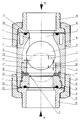
- the single figure shows a longitudinal section of a check valve.
- the check valve shown has a valve body 1 with a flow channel 2.
- the pressure ring 5 has an inlet opening 6 for the medium, which preferably has the same cross section as the outlet opening 7 of the flow channel 2 arranged on the opposite end of the housing 1.
- three guide ribs 8, which have a stop surface 9, are preferably arranged uniformly distributed on the inner circumference.
- a closure body 10 designed as a ball is displaceable and guided, which rests against the stop surfaces 9 in the direction of arrow 11 during normal media flow.
- the closure body 10 is pressed against the seal 30 by the medium pressure, so that the backflow is blocked.
- the guide ribs 8 have an end face 13 against which the ring part 4 rests.
- the inner contour of the flow channel 2 is designed to be streamlined in the direction of the outlet opening 7.
- the valve housing 1 is provided at both ends with external threads 14, 15, onto which collar nuts 16, 17 can be screwed.
- a collar bushing 18 can be pressed against the end faces 21 of the valve housing 1 provided with a seal 20 and fastened in a sealing manner to the valve housing 1.
- the pressure ring 5 is screwed directly into an internal thread 26 of the housing 1, as a result of which the ring part 4 is pressed against the end face 13 via the seal 30.
- the parts of the check valve are preferably made of a plastic such as e.g. Made of polyvinyl chloride, which makes it suitable for aggressive media.
- a plastic such as e.g. Made of polyvinyl chloride, which makes it suitable for aggressive media.
- the check valve can also be made of other materials such as Steel, copper, brass, etc.
- the seal 30 is arranged with its outer diameter centered in the housing 1 and held between the ring part 4 and the pressure ring 5.
- an annular bead of the seal 30 engages in a recess 24 of the pressure ring 5 and in a recess 25 of the ring part 4, whereby the seal 30 is firmly clamped.
- the ring part 4 has a preferably cylindrical inner bore 28 which is larger in the inside diameter 2/100 to 5/100, preferably 2.5 / 100 to 4.2 / 100 of the diameter of the ball closure body 10 than the diameter of the ball closure body 10, which gives a gap 29.
- the partial length (1) of the inner bore 28 is approx. 1/7 to 1, starting from the position of the ball equator 27 in the closed position (see dash-dot position of the ball closure body 10) in the direction of the displacement path or the flow direction according to arrow 11 / 2 - preferably 1/6 to 1/3 - of the diameter of the ball closure body 10.
- the displacement (L) of the ball closure body 10 is approximately 1/2 to 4/5 - preferably 1/2 to 3/4 of the Diameter of the ball closure body 10.
- This configuration of the inner bore 28 of the ring part 4 and the above-mentioned dimensional dependency on the ball closure body or on the displacement path means that the ball closure body 10 accelerates when the check valve is opened and comes into contact with the stop surface 9 by means of an annular medium jet which arises through the ring part 4, without vibration and back and forth beating. Damage to the ball closure body is thus largely avoided and the check valve can also be used for flow velocities of the flow medium which are greater than 2 m / sec. , it has been shown that even at low flow rates of approx. 0.5 m / sec. the ball closure body 10 comes to bear against the stop surface 9 without vibration.
- the gap 29 is so large that no particles present in the medium can get stuck or these are flushed out again when the check valve is fully opened.
Landscapes
- Engineering & Computer Science (AREA)
- General Engineering & Computer Science (AREA)
- Mechanical Engineering (AREA)
- Check Valves (AREA)
- Compressor (AREA)
- Valve-Gear Or Valve Arrangements (AREA)
Abstract
Description
- Die Erfindung betrifft ein Rückschlagventil, wie es im Oberbegriff von Anspruch 1 gekennzeichnet ist.
- Derartige Rückschlagventile sind bekannt (z.B. Prospekt der Firma Georg Fischer AG "Kugelrückschlagventil" Prospekt Nr. FI 679M vom März 1984).
- Nachteilig bei diesem Rückschlagventil ist, dass beim Öffnen des Rückschlagventils sofort ein grosser Durchflussquerschnitt entsteht, so dass bei etwas grösseren Strömungsgeschwindigkeiten des Mediums Turbulenzen und Vibrationen auftreten, durch welche der kugelige Verschlusskörper hin- und hergeschlagen wird. Dabei entstehen Abnützungen und Materialausbrüche am Verschlusskörper, wodurch auf die Dauer keine einwandfreie Dichtwirkung in Schliess-Stellung gewährleistet ist. Auch an den Anschlagflächen und Führungsrippen für den Verschlusskörper entstehen Abnützungen. Die abgenützten bzw. ausgeschlagenen Materialteile verunreinigen das Medium und können zu weiteren Schäden an anderen, im Rohrleitungssystem angeordneten Ventilen, Pumpen und anderen Armaturen führen.
- Aufgabe der vorliegenden Erfindung ist die Schaffung eines Rückschlagventils der eingangs genannten Art, bei welchem auch bei unterschiedlichen Durchflussgeschwindigkeiten Turbulenzen und somit Schläge des Verschlusskörpers und dessen Beschädigung vermieden werden.
- Erfindungsgemäss wird diese Aufgabe durch die kennzeichnenden Merkmale von Anspruch 1 gelöst.
- Besonders vorteilhafte Ausgestaltungen der Erfindung sind in den abhängigen Ansprüchen gekennzeichnet.
- Durch die erfindungsgemässe Anordnung und Ausbildung eines Ringteils anschliessend an die Dichtung wird der Kugel-Verschlusskörper durch den im Ringteil kurz nach dem Öffnen ringförmigen Strahl in zentrischer Lage beschleunigt und ohne grösseres Ausweichen bis zum Anschlag bewegt, so dass ein Schlagen des Kugel-Verschlusskörpers sowie Vibrationen verhindert werden.
- Dadurch werden Beschädigungen am Ventil und Partikel im Medium vermieden, wodurch eine dauerhafte Betriebssicherheit des Ventils gewährleistet wird.
- Es hat sich gezeigt, dass bei niedrigen als auch bei höheren als bisher üblichen Durchflussgeschwindigkeiten der Kugel-Verschlusskörper ohne Vibration an der Anschlagfläche zum Anliegen kommt.
- Die Erfindung ist in der beiliegenden Zeichnung beispielsweise dargestellt und nachfolgend beschrieben. Die einzige Figur zeigt einen Längsschnitt eines Rückschlagventils.
- Das dargestellt Rückschlagventil weist einen Ventilkörper 1 mit einem Durchflusskanal 2 auf.
- An einer Seite des Durchflusskanals 2 ist eine Dichtpartie 3 mit einer Dichtung 30 angeordnet, welche zwischen einem Ringteil 4 und einem Druckring 5 fest eingespannt ist. Der Druckring 5 weist eine Eintrittsöffnung 6 für das Medium auf, welche vorzugsweise den gleichen Querschnitt aufweist, wie die auf dem gegenüberliegenden Ende des Gehäuses 1 angeordnete Austritts-Öffnung 7 des Durchflusskanals 2.
- Im Durchflusskanal 2 sind am Innenumfang vorzugsweise drei Führungsrippen 8 gleichmässig verteilt angeordnet, welche eine Anschlagfläche 9 aufweisen. Zwischen den Führungsrippen 8 ist ein als Kugel ausgebildeter Verschlusskörper 10 verschiebbar und geführt angeordnet, welcher beim normalen Mediendurchfluss in Richtung des Pfeiles 11 an den Anschlagflächen 9 anliegt. Bei einem Rückfluss des Mediums gemäss Pfeil 12 wird der Verschlusskörper 10 durch den Mediendruck gegen die Dichtung 30 gedrückt, so dass der Rückfluss gesperrt wird. Die Führungsrippen 8 weisen eine Stirnfläche 13 auf, an welcher das Ringteil 4 anliegt.
- Die Innenkontur des Durchflusskanals 2 ist in Richtung der Austrittsöffnung 7 strömungsgünstig ausgebildet.
- Das Ventilgehäuse 1 ist an beiden Enden mit Aussengewinden 14, 15 versehen, auf welche Bundmuttern 16, 17 aufschraubbar sind.
- Mittels der Bundmutter 16 kann eine Bundbuchse 18 gegen die mit einer Dichtung 20 versehenen Endstirnflächen 21 des Ventilgehäuses 1 gedrückt und am Ventilgehäuse 1 dichtend befestigt werden.
- Mit der Bundmutter 17 wird eine Bundbuchse 19 gegen eine mit einer Dichtung 23 versehenen Endstirnfläche 22 des Druckringes 5 gedrückt.
- Der Druckring 5 ist in ein Innengewinde 26 des Gehäuses 1 direkt eingeschraubt, wodurch das Ringteil 4 über die Dichtung 30 gegen die Stirnfläche 13 gedrückt wird.
- Die Teile des Rückschlagventils sind vorzugsweise aus einem Kunststoff wie z.B. Polyvinylchlorid hergestellt, wodurch es für aggressive Medien verwendbar ist. Selbstverständlich kann das Rückschlagventil auch aus anderen Materialien wie z.B. Stahl, Kupfer, Messing usw. hergestellt sein.
- Die Dichtung 30 ist mit ihrem Aussendurchmesser im Gehäuse 1 zentriert angeordnet und zwischen dem Ringteil 4 und dem Druckring 5 gehalten. Hierbei greift je ein Ringwulst der Dichtung 30 in eine Ausnehmung 24 des Druckringes 5 und in eine Ausnehmung 25 des Ringteils 4 ein, wodurch die Dichtung 30 fest eingespannt ist.
- Der Ringteil 4 weist eine vorzugsweise zylindrische Innenbohrung 28 auf, welche im Innendurchmesser 2/100 bis 5/100, vorzugsweise 2,5/100 bis 4,2/100 des Druchmessers des Kugel-Verschlusskörpers 10 grösser ist als der Durchmesser des Kugel-Verschlusskörpers 10, was einen Spalt 29 ergibt. Die Teil-Länge (1) der Innenbohrung 28 ist ausgehend von der Lage des Kugeläquators 27 in Schliess-Stellung (siehe strichpunktierte Lage des Kugel-Verschlusskörpers 10) in Richtung des Verschiebeweges bzw. der Durchflussrichtung gemäss Pfeil 11 ca. 1/7 bis 1/2 - vorzugsweise 1/6 bis 1/3 - des Durchmessers des Kugel-Verschlusskörpers 10. Vorzugsweise beträgt der Verschiebeweg (L) des Kugel-Verschlusskörpers 10 etwa 1/2 bis 4/5 - vorzugsweise 1/2 bis 3/4 des Durchmessers des Kugel-Verschlusskörpers 10.
- Durch diese Ausbildung der Innenbohrung 28 des Ringteils 4 und die angeführte Massabhängigkeit vom Kugel-Verschluss-körper bzw.vom Verschiebeweg wird erreicht, dass beim Öffnen des Rückschlagventils der Kugel-Verschlusskörper 10 beschleunigt wird und durch einen, durch das Ringteil 4 entstehenden kreisringförmigen Mediumsstrahl zentrisch ohne Vibration und Hin- und Herschlagen an der Anschlagfläche 9 zum Anliegen kommt. Somit werden Beschädigungen des Kugel-Verschlusskörpers weitgehend vermieden und das Rückschlagventil kann auch für Strömungsgeschwindigkeiten des Durchflussmediums eingesetzt werden, die grösser als 2 m/sek. sind, wobei es sich gezeigt hat, dass auch bei niedrigen Durchflussgeschwindigkeiten von ca. 0,5 m/sek. der Kugel-Verschlusskörper 10 ohne Vibration an der Anschlagfläche 9 zum Anliegen kommt.
- Der Spalt 29 ist dabei so gross, dass sich keine im Medium vorhandene Partikel festsetzen können bzw. diese werden beim vollständigen öffnen des Rückschlagventils wieder herausgespült.
Claims (5)
- Rückschlagventil mit einem in einem Durchflusskanal eines Ventilkörpers angeordenten, durch das Durchflussmedium verschiebbaren und in Schliess-Stellung an einer Dichtpartie mit einer elastischen Dichtung anliegenden Kugel-Verschlusskörpers, welcher durch im Durchflusskanal angeordneten und Anschlagflächen aufweisenden Führungsrippen geführt ist, dadurch gekennzeichnet, dass in Durchflussrichtung (11) gesehen anschliessend an die Dichtpartie (3) ein Ringteil (4) angeordnet ist, dessen Innenbohrung (28) mit dem Kugeläquator (27) des an der Dichtung (30) anliegenden Kugel-Verschlusskörpers (10) einen engen Spalt (29) bildet, wobei die Teil-Länge (1) der Innenbohrung (28) des Ringteiles (4) ausgehend von der Lage des Kugeläquators (27) in Schliess-Stellung in Durchflussrichtung (11) 1/7 bis 1/2 des Durchmessers des Kugel-Verschlusskörpers (10) entspricht.
- Rückschlagventil nach Anspruch 1, dadurch gekennzeichnet, dass die Teil-Länge (1) 1/6 bis 1/3 des Durchmessers des Kugelverschlusskörpers (10) entspricht.
- Rückschlagventil nach Anspruch 1 oder 2, dadurch gekennzeichnet, dass der Verschiebeweg (L) des Kugelverschlusskörpers (10) 1/2 bis 4/5 des Durchmessers des Kugelverschlusskörpres (10) entspricht.
- Rückschlagventil nach einem der Ansprüche 1 bis 3, dadurch gekennzeichnet, dass die Innenbohrung (28) um 2/100 bis 5/100 des Durchmessers des Kugelverschlusskörpers (10) grösser ist als dieser.
- Rückschlagventil nach einem der Ansprüche 1 bis 4, dadurch gekennzeichnet, dass das Ringteil (4) mittels eines in ein Innengewinde (26) des Gehäuses (1) einschraubbaren Druckringes (5) gegen eine Stirnfläche (13) des Gehäuses (1) drückbar ist.
Applications Claiming Priority (2)
| Application Number | Priority Date | Filing Date | Title |
|---|---|---|---|
| DE19914108790 DE4108790A1 (de) | 1991-03-18 | 1991-03-18 | Rueckschlagventil |
| DE4108790 | 1991-03-18 |
Publications (2)
| Publication Number | Publication Date |
|---|---|
| EP0504631A1 true EP0504631A1 (de) | 1992-09-23 |
| EP0504631B1 EP0504631B1 (de) | 1999-02-03 |
Family
ID=6427576
Family Applications (1)
| Application Number | Title | Priority Date | Filing Date |
|---|---|---|---|
| EP19920103227 Expired - Lifetime EP0504631B1 (de) | 1991-03-18 | 1992-02-26 | Rückschlagventil |
Country Status (4)
| Country | Link |
|---|---|
| US (1) | US5232014A (de) |
| EP (1) | EP0504631B1 (de) |
| AT (1) | ATE176521T1 (de) |
| DE (2) | DE4108790A1 (de) |
Cited By (3)
| Publication number | Priority date | Publication date | Assignee | Title |
|---|---|---|---|---|
| WO2012106736A1 (en) * | 2011-01-31 | 2012-08-09 | Erls Mining (Pty) Ltd | Valve |
| DE102013106607A1 (de) | 2013-06-25 | 2015-01-08 | Geiger Automotive Gmbh | Schlauchanschluss mit Rückschlagventil |
| CN107781468A (zh) * | 2017-11-24 | 2018-03-09 | 中船黄埔文冲船舶有限公司 | 一种透气止回阀 |
Families Citing this family (18)
| Publication number | Priority date | Publication date | Assignee | Title |
|---|---|---|---|---|
| US5348454A (en) * | 1993-05-26 | 1994-09-20 | Graco Inc. | Liquid pump resilient inlet insert for pumping high solids content liquids |
| US5368069A (en) * | 1993-05-28 | 1994-11-29 | Eg&G Pressure Science, Inc. | Conduit joint assembly |
| US5749394A (en) * | 1996-10-09 | 1998-05-12 | Vernay Laboratories, Inc. | Check valve including molded valve seat |
| US5819792A (en) * | 1997-03-05 | 1998-10-13 | Warren Rupp, Inc. | Check ball valve seat |
| HUP9800248A1 (hu) | 1998-02-05 | 1999-12-28 | József Bereznai | Bereznai System féle csőzár-automata |
| US7082847B2 (en) * | 2003-01-30 | 2006-08-01 | Techelan, Llc | Sealing device |
| CA2628190C (en) * | 2007-04-03 | 2015-04-07 | Harbison-Fischer, Inc. | High compression downhole pump |
| US7628140B2 (en) * | 2007-09-27 | 2009-12-08 | Caterpillar Inc. | High-pressure pump or injector plug or guide with decoupled sealing land |
| JP5549005B2 (ja) * | 2009-03-31 | 2014-07-16 | 旭有機材工業株式会社 | ボールチェックバルブ |
| CN103307320B (zh) * | 2013-06-18 | 2016-06-15 | 清华大学 | 一种非能动单向隔离阀、管道及球床高温气冷堆 |
| CN105874252A (zh) * | 2014-01-02 | 2016-08-17 | 耆那灌溉系统有限公司 | 在水位线中使用的止回阀 |
| EP3374637B1 (de) | 2015-11-11 | 2021-03-17 | Graco Minnesota Inc. | Kugelkäfig mit gerichteten strömungswegen für eine kugelpumpe |
| CN107304854A (zh) * | 2016-04-18 | 2017-10-31 | 迈克尔·安东尼·迪蒙特 | 用以允许或阻止流进入到管道系统或封闭环境中的设备 |
| CA3012065A1 (en) * | 2017-07-21 | 2019-01-21 | Global Oil And Gas Supplies Inc. | Ball valve cage assembly for reciprocating downhole pump |
| US11572876B2 (en) | 2017-08-30 | 2023-02-07 | Graco Minnesota Inc. | Pump piston |
| JP7173536B2 (ja) * | 2018-10-02 | 2022-11-16 | 橋本産業株式会社 | ボール型逆止弁 |
| US11079033B2 (en) | 2019-03-05 | 2021-08-03 | Graco Minnesota Inc. | Check valve ball stop having gasket compression stand off |
| US11549613B2 (en) * | 2020-10-06 | 2023-01-10 | Vianney Rabhi | Valve plate with free micro-balls |
Citations (4)
| Publication number | Priority date | Publication date | Assignee | Title |
|---|---|---|---|---|
| DE2728486A1 (de) * | 1977-06-24 | 1979-01-04 | Zahnradfabrik Friedrichshafen | Rueckschlagventil |
| DE3003480A1 (de) * | 1980-01-31 | 1981-08-06 | Asahi Yukizai Kogyo Co., Ltd., Nobeoka, Miyazaki | Rueckschlagventil |
| GB2176267A (en) * | 1985-06-07 | 1986-12-17 | Teves Gmbh Alfred | Valve |
| EP0315797A1 (de) * | 1987-11-12 | 1989-05-17 | Georg Fischer Aktiengesellschaft | Rückschlagventil |
Family Cites Families (5)
| Publication number | Priority date | Publication date | Assignee | Title |
|---|---|---|---|---|
| US2322139A (en) * | 1942-02-18 | 1943-06-15 | Frederick C Kingston | Safety valve |
| US4197875A (en) * | 1978-05-16 | 1980-04-15 | Liquid Metronics Incorporated | Ball check valve |
| JPS5590768A (en) * | 1978-12-28 | 1980-07-09 | Seibu Suido Kiki Seisakusho:Kk | Check valve apparatus for upright-type distribution pipe line |
| US4347915A (en) * | 1980-02-25 | 1982-09-07 | General Screw Products Company | Grease fitting |
| US4474208A (en) * | 1983-04-13 | 1984-10-02 | Baird Manufacturing Company | Safety valve |
-
1991
- 1991-03-18 DE DE19914108790 patent/DE4108790A1/de active Granted
-
1992
- 1992-02-26 AT AT92103227T patent/ATE176521T1/de not_active IP Right Cessation
- 1992-02-26 DE DE59209629T patent/DE59209629D1/de not_active Expired - Fee Related
- 1992-02-26 EP EP19920103227 patent/EP0504631B1/de not_active Expired - Lifetime
- 1992-03-09 US US07/848,330 patent/US5232014A/en not_active Expired - Fee Related
Patent Citations (4)
| Publication number | Priority date | Publication date | Assignee | Title |
|---|---|---|---|---|
| DE2728486A1 (de) * | 1977-06-24 | 1979-01-04 | Zahnradfabrik Friedrichshafen | Rueckschlagventil |
| DE3003480A1 (de) * | 1980-01-31 | 1981-08-06 | Asahi Yukizai Kogyo Co., Ltd., Nobeoka, Miyazaki | Rueckschlagventil |
| GB2176267A (en) * | 1985-06-07 | 1986-12-17 | Teves Gmbh Alfred | Valve |
| EP0315797A1 (de) * | 1987-11-12 | 1989-05-17 | Georg Fischer Aktiengesellschaft | Rückschlagventil |
Cited By (3)
| Publication number | Priority date | Publication date | Assignee | Title |
|---|---|---|---|---|
| WO2012106736A1 (en) * | 2011-01-31 | 2012-08-09 | Erls Mining (Pty) Ltd | Valve |
| DE102013106607A1 (de) | 2013-06-25 | 2015-01-08 | Geiger Automotive Gmbh | Schlauchanschluss mit Rückschlagventil |
| CN107781468A (zh) * | 2017-11-24 | 2018-03-09 | 中船黄埔文冲船舶有限公司 | 一种透气止回阀 |
Also Published As
| Publication number | Publication date |
|---|---|
| US5232014A (en) | 1993-08-03 |
| DE4108790A1 (de) | 1992-09-24 |
| DE59209629D1 (de) | 1999-03-18 |
| EP0504631B1 (de) | 1999-02-03 |
| DE4108790C2 (de) | 1993-06-09 |
| ATE176521T1 (de) | 1999-02-15 |
Similar Documents
| Publication | Publication Date | Title |
|---|---|---|
| EP0504631B1 (de) | Rückschlagventil | |
| DE1450657A1 (de) | Drosselhahn | |
| EP0065593A1 (de) | Rückschlagventil | |
| DE3935448A1 (de) | Scheibenventil | |
| DE69501828T2 (de) | Hahn mit konischem küken | |
| DE1500277A1 (de) | Drosselventile und entsprechende erosionsfeste Sitze | |
| EP0315797B1 (de) | Rückschlagventil | |
| DE2525243A1 (de) | Heizungsventil | |
| EP0176528B1 (de) | Drosselorgan zur herabsetzung des drucks in förderleitungen | |
| DE8912046U1 (de) | Ventileinrichtung | |
| DE3003480C2 (de) | ||
| DE29604196U1 (de) | Absperrventil | |
| DE1185435B (de) | Absperrhahn mit einer Ringkolbendichtung fuer das Kueken | |
| DE10043079C2 (de) | Rückschlagventil mit Schwingungsdämpfung | |
| DE2853719A1 (de) | Ventil fuer fluessigkeiten mit hoher stroemungsgeschwindigkeit | |
| AT227050B (de) | Ventildichtung | |
| DE1050623B (de) | Absperrhahn mit Kugelküken | |
| AT412220B (de) | Hydrant | |
| CH625295A5 (en) | Pipe disconnecter | |
| DE1806748C3 (de) | Rückschlagventil | |
| DE1098775B (de) | Ventildichtung | |
| DE1450628C3 (de) | Strömungsgesteuerter Rückflußverhinderer | |
| AT144596B (de) | Hahn. | |
| DE102019201921A1 (de) | Rückschlagventil mit einer Ventilkörperführung | |
| DE2834132C3 (de) |
Legal Events
| Date | Code | Title | Description |
|---|---|---|---|
| PUAI | Public reference made under article 153(3) epc to a published international application that has entered the european phase |
Free format text: ORIGINAL CODE: 0009012 |
|
| 17P | Request for examination filed |
Effective date: 19920226 |
|
| AK | Designated contracting states |
Kind code of ref document: A1 Designated state(s): AT BE CH DE FR GB IT LI NL SE |
|
| 17Q | First examination report despatched |
Effective date: 19960711 |
|
| GRAG | Despatch of communication of intention to grant |
Free format text: ORIGINAL CODE: EPIDOS AGRA |
|
| GRAG | Despatch of communication of intention to grant |
Free format text: ORIGINAL CODE: EPIDOS AGRA |
|
| GRAH | Despatch of communication of intention to grant a patent |
Free format text: ORIGINAL CODE: EPIDOS IGRA |
|
| GRAH | Despatch of communication of intention to grant a patent |
Free format text: ORIGINAL CODE: EPIDOS IGRA |
|
| GRAA | (expected) grant |
Free format text: ORIGINAL CODE: 0009210 |
|
| PGFP | Annual fee paid to national office [announced via postgrant information from national office to epo] |
Ref country code: FR Payment date: 19990115 Year of fee payment: 8 |
|
| PGFP | Annual fee paid to national office [announced via postgrant information from national office to epo] |
Ref country code: SE Payment date: 19990125 Year of fee payment: 8 |
|
| PGFP | Annual fee paid to national office [announced via postgrant information from national office to epo] |
Ref country code: AT Payment date: 19990126 Year of fee payment: 8 |
|
| PGFP | Annual fee paid to national office [announced via postgrant information from national office to epo] |
Ref country code: BE Payment date: 19990201 Year of fee payment: 8 |
|
| AK | Designated contracting states |
Kind code of ref document: B1 Designated state(s): AT BE CH DE FR GB IT LI NL SE |
|
| PGFP | Annual fee paid to national office [announced via postgrant information from national office to epo] |
Ref country code: GB Payment date: 19990203 Year of fee payment: 8 |
|
| REF | Corresponds to: |
Ref document number: 176521 Country of ref document: AT Date of ref document: 19990215 Kind code of ref document: T |
|
| REG | Reference to a national code |
Ref country code: CH Ref legal event code: NV Representative=s name: ROTTMANN, ZIMMERMANN + PARTNER AG Ref country code: CH Ref legal event code: EP |
|
| GBT | Gb: translation of ep patent filed (gb section 77(6)(a)/1977) |
Effective date: 19990204 |
|
| ITF | It: translation for a ep patent filed | ||
| ET | Fr: translation filed | ||
| PGFP | Annual fee paid to national office [announced via postgrant information from national office to epo] |
Ref country code: NL Payment date: 19990315 Year of fee payment: 8 |
|
| REF | Corresponds to: |
Ref document number: 59209629 Country of ref document: DE Date of ref document: 19990318 |
|
| PLBE | No opposition filed within time limit |
Free format text: ORIGINAL CODE: 0009261 |
|
| STAA | Information on the status of an ep patent application or granted ep patent |
Free format text: STATUS: NO OPPOSITION FILED WITHIN TIME LIMIT |
|
| PGFP | Annual fee paid to national office [announced via postgrant information from national office to epo] |
Ref country code: CH Payment date: 20000117 Year of fee payment: 9 |
|
| 26N | No opposition filed | ||
| PG25 | Lapsed in a contracting state [announced via postgrant information from national office to epo] |
Ref country code: GB Free format text: LAPSE BECAUSE OF NON-PAYMENT OF DUE FEES Effective date: 20000226 Ref country code: AT Free format text: LAPSE BECAUSE OF NON-PAYMENT OF DUE FEES Effective date: 20000226 |
|
| PG25 | Lapsed in a contracting state [announced via postgrant information from national office to epo] |
Ref country code: SE Free format text: LAPSE BECAUSE OF NON-PAYMENT OF DUE FEES Effective date: 20000227 |
|
| PG25 | Lapsed in a contracting state [announced via postgrant information from national office to epo] |
Ref country code: BE Free format text: LAPSE BECAUSE OF NON-PAYMENT OF DUE FEES Effective date: 20000228 |
|
| BERE | Be: lapsed |
Owner name: GEORG FISCHER A.G. Effective date: 20000228 |
|
| PG25 | Lapsed in a contracting state [announced via postgrant information from national office to epo] |
Ref country code: NL Free format text: LAPSE BECAUSE OF NON-PAYMENT OF DUE FEES Effective date: 20000901 |
|
| EUG | Se: european patent has lapsed |
Ref document number: 92103227.2 |
|
| GBPC | Gb: european patent ceased through non-payment of renewal fee |
Effective date: 20000226 |
|
| PG25 | Lapsed in a contracting state [announced via postgrant information from national office to epo] |
Ref country code: FR Free format text: LAPSE BECAUSE OF NON-PAYMENT OF DUE FEES Effective date: 20001031 |
|
| NLV4 | Nl: lapsed or anulled due to non-payment of the annual fee |
Effective date: 20000901 |
|
| REG | Reference to a national code |
Ref country code: FR Ref legal event code: ST |
|
| PG25 | Lapsed in a contracting state [announced via postgrant information from national office to epo] |
Ref country code: LI Free format text: LAPSE BECAUSE OF NON-PAYMENT OF DUE FEES Effective date: 20010228 Ref country code: CH Free format text: LAPSE BECAUSE OF NON-PAYMENT OF DUE FEES Effective date: 20010228 |
|
| REG | Reference to a national code |
Ref country code: CH Ref legal event code: PL |
|
| PGFP | Annual fee paid to national office [announced via postgrant information from national office to epo] |
Ref country code: DE Payment date: 20020207 Year of fee payment: 11 |
|
| PG25 | Lapsed in a contracting state [announced via postgrant information from national office to epo] |
Ref country code: DE Free format text: LAPSE BECAUSE OF NON-PAYMENT OF DUE FEES Effective date: 20030902 |
|
| PG25 | Lapsed in a contracting state [announced via postgrant information from national office to epo] |
Ref country code: IT Free format text: LAPSE BECAUSE OF NON-PAYMENT OF DUE FEES;WARNING: LAPSES OF ITALIAN PATENTS WITH EFFECTIVE DATE BEFORE 2007 MAY HAVE OCCURRED AT ANY TIME BEFORE 2007. THE CORRECT EFFECTIVE DATE MAY BE DIFFERENT FROM THE ONE RECORDED. Effective date: 20050226 |