EP0504582B1 - Thermostatkopf für das Steuerventil eines Heizkörpers - Google Patents
Thermostatkopf für das Steuerventil eines Heizkörpers Download PDFInfo
- Publication number
- EP0504582B1 EP0504582B1 EP92102174A EP92102174A EP0504582B1 EP 0504582 B1 EP0504582 B1 EP 0504582B1 EP 92102174 A EP92102174 A EP 92102174A EP 92102174 A EP92102174 A EP 92102174A EP 0504582 B1 EP0504582 B1 EP 0504582B1
- Authority
- EP
- European Patent Office
- Prior art keywords
- sleeve
- knob
- clamping
- connecting piece
- clamping jaws
- Prior art date
- Legal status (The legal status is an assumption and is not a legal conclusion. Google has not performed a legal analysis and makes no representation as to the accuracy of the status listed.)
- Expired - Lifetime
Links
Images


Classifications
-
- G—PHYSICS
- G05—CONTROLLING; REGULATING
- G05D—SYSTEMS FOR CONTROLLING OR REGULATING NON-ELECTRIC VARIABLES
- G05D23/00—Control of temperature
- G05D23/01—Control of temperature without auxiliary power
- G05D23/02—Control of temperature without auxiliary power with sensing element expanding and contracting in response to changes of temperature
- G05D23/021—Control of temperature without auxiliary power with sensing element expanding and contracting in response to changes of temperature the sensing element being a non-metallic solid, e.g. elastomer, paste
- G05D23/023—Control of temperature without auxiliary power with sensing element expanding and contracting in response to changes of temperature the sensing element being a non-metallic solid, e.g. elastomer, paste the sensing element being placed outside a regulating fluid flow
Definitions
- the above invention relates to a thermostatic head for the control valve of a radiator of a heating system, according to the preamble of claim 1.
- Thermostatic heads for radiator valves are already known which have a locking part which is designed as a clamp-like locking part which can be clamped around the pipe socket with the aid of a screw and a nut.
- the pliers-shaped components In order to ensure a correct positional arrangement during the tensioning process of the locking part on the connecting pliers of the connecting piece, the pliers-shaped components have an annular outer groove. The inner surface of the clamp-like locking part engages in this groove with a positive connection.
- the connecting piece In the vicinity of the cheek-shaped components, has a construction length which enables the ring-shaped pipe clamp in a rest position, ie out of operative connection with the ring groove, to be arranged on the outside of the tong-shaped components.
- the cheek-shaped components can carry out the elastic spreading movement which is required for mounting the thermostatic head on the tubular end piece of the control valve of the radiator.
- the adjusting knob of the thermostatic head can be screwed onto the socket of the known thermostatic head.
- the end of the thermostatic head facing the radiator valve is designed as a connecting piece which consists of clamping jaws which can be expanded elastically and radially apart.
- a circumferential groove is provided on the inside of the clamping jaws, the cross section of which is adapted to the shape of a thickening formed on the connecting piece of the radiator valve.
- a clamping sleeve is axially displaceable on the clamping jaws from a rest position in which the sleeve is disengaged from the clamping area of the clamping jaws and the clamping jaws can be expanded for mounting on the radiator valve, in a clamping position in which the sleeve engages with the clamping area means with the free end of the jaws.
- the disclosed design of the clamping sleeve and the clamping jaws does not allow the clamping jaws to be freely expanded when the thermostatic head is mounted on the radiator valve. With this thermostatic head an automatic displacement of the sleeve from the rest position to the clamping position during assembly on the radiator valve is also not feasible.
- thermostatic head of the type mentioned with which the disadvantages of the prior art can be avoided and which is equipped with a clamping part, which can be lost Additional parts are missing and which also allows the thermostatic head piece to be clamped on the valve of the radiator only in the position provided for the bracing.
- the advantage that can be achieved with the thermostatic head according to the invention is mainly that the clamping part can be produced in one piece and does not require any subsequent processing.
- thermostatic head can be tightened by hand, ie without the use of tools. This enables the installation time of the thermostatic head to be shortened considerably.
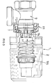
- the thermostatic head is marked in its entirety with 1. It consists in a manner known per se from a bell-shaped rotary handle 2 with which the heating power can be adjusted.
- a thermostatic control element not shown and designated 115 in FIG. 3, is installed in the interior of the rotary handle 2 in FIGS. 1 and 2.
- the bell-shaped rotary handle 2 is slidably screwed onto a connecting piece 3 and can be between one Position, which corresponds to the maximum valve opening (Fig. 1), and a closed position (shown in Fig. 2 with chain lines).
- the connector 3 has a connecting end 12 which has clamping jaws 4 which are arranged in a known manner in the circumferential direction and are separated from one another by axial incisions 5.
- the mounting jaws 4 extend in the circumferential direction and on their inner surface they have a circumferential groove 6.
- the cross section of the circumferential groove 6 is adapted to the shape of an annular thickening 7, which is provided on a connecting piece 8 of the valve body 9 of the radiator valve, not shown.
- a control pin of the radiator valve 9 is shown in FIG. 1 by reference number 10. This pin is in operative connection with a thermocouple (115 in FIG. 3) which is provided in the interior of the thermostatic head 2.
- the clamping sleeve which cooperate with the clamping jaws 4 for the fixed connection of the thermostatic head on the connecting piece of the control valve 9 of the heating body, consists of a sleeve 11 which is arranged in the longitudinal direction on the connecting piece 3.
- the inner surface of the sleeve 11 and the outer surface of the clamping jaws 4 have a stepped design in the clamping region 12.
- the surfaces to be joined which can advantageously be connected with a form fit, are conceivable, for example frustoconical or similar surfaces.
- the connecting piece 3 and the sleeve 11 are advantageously made of plastic.
- the sleeve 11 has bell-shaped extension 13 on the side facing the rotary handle 2, which has an outer diameter that corresponds to the outer diameter of the free end of the rotary handle 2 facing the sleeve 11 .
- the length of the bell-shaped widening 13 is chosen such that when the sleeve 11 is in the rest position, the free end of the bell-shaped widening 13 rests against the free end of the rotary handle 2 with the maximum valve opening (FIG. 1).
- valve body 9 with a pin-like projection of the valve body 9 is identified, which cooperates in a known manner with a recess, not shown, on the connecting piece 3, in order to enable a correct positional arrangement of the components during the assembly of the thermostatic head 1.
- the method of operation of the thermostatic head according to the invention is as follows:
- the sleeve 11 can be plugged in by simply compressing the clamping jaws 4 in the radial direction onto the nozzle end 12 consisting of the clamping jaws 4.
- the sleeve 11 may have one or more chamfers in the circumferential direction, as is e.g. is indicated by the reference number 16 in FIG. 2.
- FIG. 3 shows another embodiment of the thermostatic head 1 designed according to the invention.
- the clamping sleeve 11 is displaced by the free end of the rotary handle 2
- an elastic clamping sleeve 111 is provided according to FIG. 3, one in diameter has a reduced collar 114 which projects into the interior of the thermostatic head 1.
- thermocouple 115 acts on the collar 114, which likewise performs a displacement movement in the direction of the arrow (f) when the rotary handle 2 rotates.
- the embodiment according to FIG. 3 has the advantage that the Clamping sleeve 111 has very small dimensions and there is no ring-shaped opening on the circumference of the thermostatic head 1, in which dirt could accumulate, for example.
- the operation of the tensioning sleeve 111 corresponds to the operation of the tensioning sleeve 11 according to FIGS. 1 and 2, i.e.
- the clamping sleeve 111 can also be pushed out of a rest position due to a longitudinal displacement in the direction of the arrow f via a collet-like extension 112 of the thermostatic head in order to enable a positive connection between the pliers-like extension 112 of the thermostatic head 1 and the connecting piece 8 projecting from the valve 9.
Landscapes
- Physics & Mathematics (AREA)
- Fluid Mechanics (AREA)
- General Physics & Mathematics (AREA)
- Engineering & Computer Science (AREA)
- Automation & Control Theory (AREA)
- Preventing Unauthorised Actuation Of Valves (AREA)
- Temperature-Responsive Valves (AREA)
- Mechanically-Actuated Valves (AREA)
- Clamps And Clips (AREA)
Description
- Die vorstehende Erfindung betrifft einen Thermostatkopf fuer das Steuerventil eines Heizkoerpers einer Heizungsanlage, entsprechend dem Oberbegriff des Anspruchs 1.
- Es sind bereits Thermostatkoepfe fuer Heizkoerperventile bekannt, die ein Feststellteil aufweisen, das als rohrschellenartiges Feststellteil ausgebildet ist, das unter Zuhilfenahme einer Schraube und einer Mutter um den Rohrstutzen verspannbar ist. Um eine ordnungsgemaesse Lageanordnung waehrend des Spannvorganges des Feststellteiles auf den Verbindungszangen des Verbindungsstutzens zu gewaehrleisten, weisen die zangenfoermig ausgebildeten Bauteile eine ringfoermige Aussennut auf. In diese Nut greift mit formschluessiger Verbindung die Innenflaeche des rohrschellenartigen Feststellteils ein. Der Stutzen weist in der Naehe der backenfoermigen Bauteile eine Baulaenge auf, die es ermoeglicht, die ringfoermig angeordnete Rohrschelle in einer Ruhelage, d.h. ausser Wirkverbindung mit der Ringnut, auf der Aussenseite der zangenfoermigen Bauteile anzuordnen. Befindet sich die Rohrschelle in Ruhelage, so koennen die backenfoermigen Bauteile die elastische Spreizbewegung durchfuehren, die fuer die Montage des Thermostatkopfes auf dem rohrfoermigen Endstueck des Steuerventils des Heizkoerpers erforderlich ist. Auf dem Stutzen der bekannten Thermostatkoepfe kann der Einstelldrehgriff des Thermostatkopfes aufgeschraubt werden.
- Bei den bekannten Thermostatkoepfen sind im wesentlichen zwei Nachteile festzustellen. Die Schraube sowie die Spannmutter der Rohrschelle stellen zusaetzliche Bauteile dar, die nicht nur verloren werden koennen, sondern zu einer Verteuerung der Spanneinrichtung fuehren. Ferner sind Schraube und Mutter in der Rohrschelle zu montieren und gegenseitig zu verbinden. Es besteht die Gefahr, dass aus Gruenden der Zeitersparnis durch den Heizungsmonteur die bisher uebliche Rohrschelle in ihrer Ruhelage verspannt wird. Dies fuehrt zu einer ungenauen Montage sowie zu einem fehlerhaften Einstellen der gewuenschten Heizungstemperatur.
- Das Dokument DE-A-3 521 965 offenbart einen Thermostat fuer Heizkoerperventile. Derartige Thermostate sind auch als Thermostatkoerper bezeichnet.
- Das dem Heizkoerperventil zugewandte Ende des Thermostatkopfes ist als Verbindungsstutzen ausgebildet, der aus elastisch radial auseinander spreizbaren Spannbacken besteht. Auf der Innenseite der Spannbacken ist eine Umfangsnut vorgesehen, deren Querschnitt der Form einer auf dem Verbindungsstutzen des Heizkoerperventils angeformten Verdickung angepasst ist. Eine Spannhuelse ist auf die Spannbacken von einer Ruhelage, in der die Huelse mit dem Spannbereich der Spannbacken ausser Eingriff ist und die Spannbacken zur Montage auf das Heizkoerperventil aufweitbar sind, in eine Spannlage axial verschiebbar, in der die Huelse in Eingriff mit dem Spannbereich, das heisst mit dem freien Ende der Spannbacken ist.
- Die offenbarte Gestaltung der Spannhuelse und der Spannbacken laesst kein freies Aufweiten der Spannbacken bei der Montage des Thermostatkopfes auf das Heizkoerperventil zu. Mit diesem Thermostatkopf ist ferner eine automatische Verschiebung der Huelse von der Ruhelage in die Spannlage bei der Montage auf das Heizkoerperventil nicht durchfuehrbar.
- Es ist daher Aufgabe der vorstehenden Erfindung, einen Thermostatkopf der genannten Art vorzuschlagen, mit dem die Nachteile des Standes der Technik vermieden werden koennen und der mit einem Festspannteil ausgeruestet ist, dem verlierbare Zusatzteile fehlen und der ferner ein Spannen des Thermostatkopfstutzens auf dem Ventil des Heizkoerpers nur in der fuer die Verspannung vorgesehenen Lage erlaubt.
- Bei dem erfindungsgemaess ausgebildeten Thermostatkopf wird diese Aufgabe durch die Merkmale des Anspruches 1 geloest. Weitere vorteilhafte Ausgestaltungen der Erfindung sind in den Unteranspruechen 2 und 3 beschrieben.
- Der mit dem erfindungsgemaessen Thermostatkopf erzielbare Vorteil besteht hauptsaechlich darin, dass das Festspannteil einstueckig herstellbar ist und keine nachtraegliche Bearbeitung erfordert.
- Ein besonderer Vorteil der Erfindung ist darin zu sehen, dass das Festspannen des Thermostatkopfes von Hand erfolgen kann, d.h. ohne den Einsatz von Werkzeugen. Dies ermoeglicht es, die Installationszeit des Thermostatkopfes wesentlich zu verkuerzen.
- Zwei Ausfuehrungsbeispiele der Erfindung werden nun genauer beschrieben und in den Zeichnungen dargestellt. Es zeigen:
- Fig. 1 eine Seitenansicht einer ersten Ausfuehrungsform eines Thermostatkopfes mit Verbindungsende im Schnitt, vor Montage des Thermostatkopfes auf dem Koerper eines Heizkoerperventiles;
- Fig. 2 eine Darstellung gemaess Fig. 1 mit dem Thermostatkopf in montierter Lage am Koerper des Heizkoerperventiles;
- Fig. 3 zeigt eine weitere Ausfuehrungsform des erfindungsgemaessen Thermostatkopfes.
- Der Thermostatkopf wird in seiner Gesamtheit mit 1 gekennzeichnet. Es besteht in an sich bekannter Weise aus einem glockenfoermigen Drehgriff 2, mit dem die Heizleistung einstellbar ist. Zu diesem Zweck ist im Inneren des Drehgriffes 2 in Fig. 1 und 2 ein nicht dargestelltes und in Fig. 3 mit 115 bezeichnetes thermostatisches Steuerelement einqebaut.
- Der glockenfoermige Drehgriff 2 ist verschiebbar auf einem Anschlußstutzen 3 aufgeschraubt und kann zwischen einer Stellung, die der maximalen Ventiloeffnung (Fig. 1 ) -entspricht, und einer Verschlußstellung (in Fig. 2 mit Strichpunktlinien dargestellt) verschoben werden. Der Stutzen 3 weist ein Verbindungsende 12 auf, das Spannbacken 4 aufweist, die in bekannter Weise in Umfangsrichtung angeordnet sind und untereinander durch Axialeinschnitte 5 getrennt sind.
- In den dargestellten Beispielen sind vier Spannbacken 4 vorgesehen. Die Befestigungsbacken 4 erstrecken sich in Umfangsrichtung und auf ihrer Innenflaeche weisen sie eine Umfangsnut 6 auf. In bekannter Weise ist der Querschnitt der Umfangsnut 6 an die Form einer ringfoermigen Verdickung 7 angepasst, die an einem Verbindungsstutzen 8 des Ventilkoerpers 9 des nicht dargestellten Heizkoerperventiles vorgesehen ist. Mit dem Bezugszeichen 10 ist in Fig. 1 ein Steuerstift des Heizkoerperventiles 9 dargestellt. Dieser Stift steht mit einem Thermoelement (115 in Fig. 3), das im Inneren des Thermostatkopfes 2 vorgesehen ist, in Wirkverbindung.
- Erfindungsgemaess besteht die Spannhuelse, die mit den Spannbacken 4 zur festen Verbindung des Thermostatkopfes auf dem Verbindungsstutzen des Steuerventils 9 des Heizkoerpers zusammenarbeiten, aus einer Huelse 11, die in Laengsrichtung auf dem Stutzen 3 verschiebbar angeordnet ist.
- In den dargestellten Beispielen weist die Innenflaeche der Huelse 11 und die Aussenflaeche der Spannbacken 4 im Spannbereich 12 stufenfoermige Ausbildung auf. Es sind natuerlich auch andere Ausfuehrungsformen fuer die zusammenzufuegenden Flaechen, die in vorteilhafter Weise mit Formschluss verbindbar sind, denkbar, z.B. kegelstumpfartig ausgebildete oder aehnliche Flaechen.
- Wie der Fig. 1 zu entnehmen ist, ist zwischen der sich in Ruhelage befindlichen Huelse 11 und der Aussenflaeche der Spannbacken 4 ein gewisses Spiel vorgesehen.
- Der Verbindungsstutzen 3 und die Huelse 11 sind in vorteilhafter Weise aus Kunststoff hergestellt.
- In dem bevorzugten Ausfuehrungsbeispiel, das in Fig. 1u.2 dargestellt ist, weist die Huelse 11 auf der dem Drehgriff 2 zugewandten Seite glockenfoermige Erweiterung 13 auf, die einen Aussendurchmesser hat, der dem Aussendurchmesser des der Huelse 11 zugewandten freien Ende des Drehgriffes 2 entspricht. Die Laenge der glockenfoermigen Aufweitung 13 ist so gewaehlt, dass bei in Ruhelage befindlicher Huelse 11, das freie Ende der glockenfoermigen Erweiterung 13 am freien Ende des Drehgriffes 2 bei maximaler Ventiloeffnung (Fig. 1) anliegt.
- Mit 14 ist ein zapfenartiger Vorsprung des Ventilkoerpers 9 gekennzeichnet, der in bekannter Weise mit einer nicht dargestellten Ausnehmung am Verbindungsstutzen 3 zusammenwirkt, um eine ordnungsgemaesse Lageanordnung der Bauteile waehrend der Montage des Thermostatkopfes 1 zu ermoeglichen.
- Die Arbeitsweise des erfindungsgemaessen Thermostatkopfes ist folgende:
- Die Huelse 11 ist durch einfaches Zusammendruecken der Spannbacken 4 in Radialrichtung auf das aus den Spannbacken 4 bestehende Stutzenende 12 aufsteckbar.
- Wird bei der Montage der Stutzen 3 unter Aufbringung einer leichten Schubkraft in Richtung auf den Verbindungsstutzen 8 des Ventilkoerpers 9 verschoben, erfolgt ein elastisches Aufweiten der Spannbacken 4. Durch den inneren Ringwulst 15 wird ein Anschlag gebildet, der den Montagehub des Thermostatkopfes 1 begrenzt. Die Spannbacken 4 schliessen sich elastisch, wobei der Ringwulst 7 in der Ringnut 6 zu liegen kommt. Fuer die sichere Befestigung des Stutzens 3 auf dem Ventilkoerper 9 ist es nun erforderlich, die Huelse 11 axial aus der Ruhelage (Fig. 1) in die Spannlage (Fig. 2) zu verschieben. Mit einer glockenfoermig ausgebildeten Huelse 11 erfolgt diese Verschiebung automatisch durch eine Drehbewegung des Drehgriffes 2 aus der Stellung maximaler Ventiloeffnung (Fig. 1) in die Stellung des Ventilabschlusses (Strichpunktlinien in Fig. 2).
- Um eine einwandfreie Montage der Huelse 11 auch bei Ventilkoerpern 9 mit groesseren Abmessungen zu ermoeglichen, z. B. bei groesseren Vierwegeventilen, kann die Huelse 11 eine oder mehrere Anfasungen in Umfangsrichtung aufweisen, wie dies z.B. mit dem Bezugszeichen 16 in Fig. 2 angedeutet ist.
- Der Fig. 3 kann eine weitere Ausfuehrungsform des erfindungsgemaess ausgebildeten Thermostatkopfes 1 entnommen werden. Waehrend in Fig. 2 die Spannhuelse 11 durch das freie Ende des Drehgriffes 2 verschoben wird, ist nach Fig. 3 eine elastische Spannhuelse 111 vorgesehen, die einen im Durchmesser verkleinerten Bund 114 aufweist, der in das Innere des Thermostatkopfes 1 ragt.
- Auf den Bund 114 wirkt bei einer Drehbewegung des Drehgriffes 2 ein zylinderfoermiger Einsatz (Thermoelement 115 ein, der ebenfalls bei einer Drehbewegung des Drehgriffes 2 eine Verschiebebewegung in Richtung des Pfeiles (f) durchfuehrt. Die Ausfuehrungsform gemaess Fig. 3 hat den Vorteil, dass die Spannhuelse 111 sehr kleine Abmessungen aufweist und am Umfang des Thermostatkopfes 1 keine ringfoermige Oeffnung verbleibt, in der sich z. B. Schmutz ablagern koennte.
- Die Funktionsweise der Spannhuelse 111 entspricht der Arbeitsweise der Spannhuelse 11 gemaess Fig. 1 und 2, d.h. auch die Spannhuelse 111 kann aus einer Ruhelage aufgrund einer Laengsverschiebung in Richtung des Pfeiles f ueber eine spannzangenartige Verlaengerung 112 des Thermostatkopfes geschoben werden, um eine formschluessige Verbindung zwischen der zangenartigen Verlaengerung 112 des Thermostatkopfes 1 und dem vom Ventil 9 abstehenden Verbindungsstutzen 8 zu ermoeglichen.
Claims (3)
- Thermostatkopf (1) fuer das Steuerventil (9) eines Heizkoerpers einer Heizungsanlage, bestehend aus einem einstellbaren gehaeuseartigen Drehgriff (2) und einem am Heizkoerperventil (9) fest anbringbaren Verbindungsstutzen (3), einem im Thermostatkopf (1) aufgenommenen und mit dem Drehgriff (2) wirkverbundenen Thermostat (115), wobei das Verbindungsende (12) des Verbindungsstutzens (3) als Spannbereich ausgefuehrt ist, der von elastisch radial auseinander spreizbaren Spannbacken (4) gebildet ist, die auf ihrer Innenseite eine Umfangsnut (6) aufweisen, deren Querschnitt der Form einer auf dem Verbindungsstutzen (8) des Heizkoerperventils (9) vorgesehenen Verdickung (7) angepasst ist, sowie einer auf den Verbindungsstutzen (3) des Thermostatkopfes (1) angebrachten glockenfoermigen Huelse (11), die von einer Ruhelage, in der die Huelse (11) mit dem Spannbereich (12) der Spannbacken (4) ausser Eingriff ist, in eine Festlage axial verschiebbar ist, in der die Huelse den Spannbereich (12) der Spannbacken (4) umgibt, dadurch gekennzeichnet, dass der Drehgriff (2) auf dem Verbindungsstutzen (3) des Thermostatkopfes (1) aufschraubbar aufgenommen ist, dass die Innenflaeche der Huelse (11) und die Aussenflaeche der Spannbacken (4) im Spannbereich (12) stufenfoermige Form aufweisen, und dass bei sich in der Ruhelage befindlicher Huelse (11) das dem Drehgriff (2) zugewandte Ende der Huelse (11) am Ende des Drehgriffes (2) bzw. am Thermoelement bei maxialer Ventiloeffnung anliegt, so dass beim Drehen des Drehgriffes (2) in die Schließstellung des Thermostatkopfes (1) die Huelse (11) auf den Spannbereich (12) der Spannbacken verschoben wird.
- Thermostatkopf (1) nach Anspruch 1, dadurch gekennzeichnet, dass das dem Drehgriff (2) zugewandte Ende der Huelse (11) eine glockenfoermige Aufweitung (13) aufweist, deren Aussendurchmesser dem Aussendurchmesser des der Huelse (11) zugewandten Drehgriffendes entspricht, und dass bei sich in Ruhelage befindlicher Huelse (11) die Aufweitung (13) am Drehgriff liegt.
- Thermostatkopf (1) nach Anspruch 1, dadurch gekennzeichnet, dass das dem Drehgriff (2) zugewandte Ende der Hülse (111) einen Bund (114) mit kleinerem Durchmesser als der Innendurchmesser der Spannbacken (4) aufweist, und dass bei sich in Ruhelage befindlicher Huelse (111) der Bund (114) an einem Thermostatkopfteil liegt, das mit dem Thermostat (115) wirkverbunden und mit dem Drehgriff (2) axial verschiebbar ist.
Applications Claiming Priority (2)
| Application Number | Priority Date | Filing Date | Title |
|---|---|---|---|
| ITMI910728A IT1247905B (it) | 1991-03-19 | 1991-03-19 | Testa termostatica per radiatori di impianti di riscaldamento |
| ITMI910728 | 1991-03-19 |
Publications (3)
| Publication Number | Publication Date |
|---|---|
| EP0504582A2 EP0504582A2 (de) | 1992-09-23 |
| EP0504582A3 EP0504582A3 (en) | 1993-04-07 |
| EP0504582B1 true EP0504582B1 (de) | 1997-09-10 |
Family
ID=11359112
Family Applications (1)
| Application Number | Title | Priority Date | Filing Date |
|---|---|---|---|
| EP92102174A Expired - Lifetime EP0504582B1 (de) | 1991-03-19 | 1992-02-10 | Thermostatkopf für das Steuerventil eines Heizkörpers |
Country Status (6)
| Country | Link |
|---|---|
| EP (1) | EP0504582B1 (de) |
| DE (2) | DE4134329A1 (de) |
| DK (1) | DK0504582T3 (de) |
| ES (1) | ES2107474T3 (de) |
| FR (1) | FR2674308B1 (de) |
| IT (1) | IT1247905B (de) |
Cited By (2)
| Publication number | Priority date | Publication date | Assignee | Title |
|---|---|---|---|---|
| EP4484833A1 (de) * | 2023-06-27 | 2025-01-01 | IMI Hydronic Engineering International SA | Adapter zur befestigung einer steuerungsvorrichtung an einer ventilanordnung |
| EP4484832A1 (de) * | 2023-06-27 | 2025-01-01 | IMI Hydronic Engineering International SA | Kit mit einer steuerungsvorrichtung und adapter zur befestigung der steuerungsvorrichtung an einer ventilanordnung |
Families Citing this family (7)
| Publication number | Priority date | Publication date | Assignee | Title |
|---|---|---|---|---|
| SE502062C2 (sv) * | 1993-11-24 | 1995-07-31 | Tour & Andersson Ab | Koppling i synnerhet för anslutning av en termostatkropp till en ventil för ett värme- eller kylelement |
| DE4344773A1 (de) * | 1993-12-28 | 1995-06-29 | Danfoss As | Thermostataufsatz für Heizkörperventile |
| DE4442402C2 (de) * | 1994-11-30 | 1998-12-24 | Oventrop Sohn Kg F W | Thermostatkopf für Heizungsventile |
| DE19612312C5 (de) * | 1996-03-28 | 2004-03-04 | Theodor Heimeier Metallwerk Gmbh & Co. Kg | Thermostatventil-Kopf für Heizungsanlagen |
| ITMI20020398U1 (it) * | 2002-08-08 | 2004-02-09 | Oliveira & Irmao Sa | Dispositivo di connessione di una testa di comando ad una valvola term ostatica in particolare per un radiatore o altro apparecchio di climat izzazione o riscaldamento |
| CN100467923C (zh) * | 2004-05-18 | 2009-03-11 | F·W·奥文特罗普有限责任两合公司 | 恒温器 |
| ES2332548B1 (es) * | 2006-02-27 | 2011-01-04 | Orkli, S. Coop. | Maneta termostatizable adaptada para la conexion a una valvula de apertura y cierre. |
Citations (1)
| Publication number | Priority date | Publication date | Assignee | Title |
|---|---|---|---|---|
| DE3521965A1 (de) * | 1985-06-20 | 1987-01-02 | Wella Ag | Thermostat fuer heizkoerperventile |
Family Cites Families (3)
| Publication number | Priority date | Publication date | Assignee | Title |
|---|---|---|---|---|
| CH581299A5 (de) * | 1975-02-20 | 1976-10-29 | Landis & Gyr Ag | |
| DE2603461C3 (de) * | 1976-01-30 | 1978-07-27 | Danfoss A/S, Nordborg (Daenemark) | Thermostatisches Regelventil |
| DE3336016C1 (de) * | 1983-10-04 | 1985-02-14 | Theodor Heimeier Metallwerk Gmbh, 4782 Erwitte | Diebstahlsicherung für den Thermostatkopf von Heizkörperventilen |
-
1991
- 1991-03-19 IT ITMI910728A patent/IT1247905B/it active IP Right Grant
- 1991-10-17 DE DE4134329A patent/DE4134329A1/de not_active Withdrawn
- 1991-10-21 FR FR9112986A patent/FR2674308B1/fr not_active Expired - Fee Related
-
1992
- 1992-02-10 DE DE59208878T patent/DE59208878D1/de not_active Expired - Lifetime
- 1992-02-10 DK DK92102174.7T patent/DK0504582T3/da active
- 1992-02-10 ES ES92102174T patent/ES2107474T3/es not_active Expired - Lifetime
- 1992-02-10 EP EP92102174A patent/EP0504582B1/de not_active Expired - Lifetime
Patent Citations (1)
| Publication number | Priority date | Publication date | Assignee | Title |
|---|---|---|---|---|
| DE3521965A1 (de) * | 1985-06-20 | 1987-01-02 | Wella Ag | Thermostat fuer heizkoerperventile |
Cited By (2)
| Publication number | Priority date | Publication date | Assignee | Title |
|---|---|---|---|---|
| EP4484833A1 (de) * | 2023-06-27 | 2025-01-01 | IMI Hydronic Engineering International SA | Adapter zur befestigung einer steuerungsvorrichtung an einer ventilanordnung |
| EP4484832A1 (de) * | 2023-06-27 | 2025-01-01 | IMI Hydronic Engineering International SA | Kit mit einer steuerungsvorrichtung und adapter zur befestigung der steuerungsvorrichtung an einer ventilanordnung |
Also Published As
| Publication number | Publication date |
|---|---|
| EP0504582A3 (en) | 1993-04-07 |
| DE59208878D1 (de) | 1997-10-16 |
| DK0504582T3 (da) | 1998-04-20 |
| EP0504582A2 (de) | 1992-09-23 |
| FR2674308A1 (fr) | 1992-09-25 |
| FR2674308B1 (fr) | 1995-04-07 |
| ITMI910728A0 (it) | 1991-03-19 |
| DE4134329A1 (de) | 1992-09-24 |
| IT1247905B (it) | 1995-01-05 |
| ES2107474T3 (es) | 1997-12-01 |
| ITMI910728A1 (it) | 1992-09-19 |
Similar Documents
| Publication | Publication Date | Title |
|---|---|---|
| EP0219661B1 (de) | Kunststoffrohrverbindung | |
| DE2347409C2 (de) | Rohrkupplung, insbesondere für sanitäre Zwecke | |
| EP1101054B1 (de) | Ventil für warmwasseranlagen | |
| EP0504582B1 (de) | Thermostatkopf für das Steuerventil eines Heizkörpers | |
| DE3034057A1 (de) | Ausruecklager | |
| DE69323686T2 (de) | Rückschlagventil-Betätigungsvorrichtung | |
| DE102015002942A1 (de) | Betätigungsanordnung für eine Betätigungseinheit einer Unterputz-Sanitärarmatur | |
| DE19955259C2 (de) | Ventil, insbesondere Thermostatventil für Heizungsanlagen | |
| DE69803638T2 (de) | Kupplungssteuerungsvorrichtung | |
| DE9420412U1 (de) | Ventil für Heizungs-, Warmwasser- oder Kühlanlagen | |
| DE3743707C2 (de) | Ventil mit Voreinstellung der Durchflußmenge | |
| EP0039476A2 (de) | Vorrichtung zum Anschluss eines Heizkörperventils, insbesondere Thermostatventils, an einen Heizkörper | |
| DE2852820C2 (de) | Thermostatkopf für Heizungsventile | |
| DE3205246A1 (de) | Bolzen fuer paneel-befestigungselement | |
| DE2949649C2 (de) | Kugelhahn | |
| DE3843030C1 (de) | ||
| DE2642641C3 (de) | Vorläufige Schutzkappe zur Anbringung an einem Absperrventil | |
| DE19837146B4 (de) | Brandschutzeinsatz für gasführende Rohrdurchgänge | |
| DE4242664A1 (de) | Heizkörperthermostatkopf mit Überwurfmutterabdeckung | |
| DE2341355A1 (de) | Schalter fuer regelkreise | |
| DE19507716C1 (de) | Schallentkoppelte Befestigung einer Rohrmuffe oder dergleichen | |
| DE202023100855U1 (de) | Anordnung zur Steuerung der Temperatur in einem Trinkwassererwärmer | |
| DE202023101164U1 (de) | Ventiloberteil für Sanitärarmaturen | |
| DE1913968C (de) | Aus Blechformlingen hergestellte Anschlußstutzen für einen Zylinderhahn | |
| EP0692344B1 (de) | Montageelement für ein Einsatzteil insbesondere einer Druckleitungs-Anschlussvorrichtung |
Legal Events
| Date | Code | Title | Description |
|---|---|---|---|
| PUAI | Public reference made under article 153(3) epc to a published international application that has entered the european phase |
Free format text: ORIGINAL CODE: 0009012 |
|
| AK | Designated contracting states |
Kind code of ref document: A2 Designated state(s): BE CH DE DK ES FR GB IT LI |
|
| XX | Miscellaneous (additional remarks) |
Free format text: PRIORITAETSERKLAERUNG: ITALIEN MI91A-000728, ANMELDETAG: 19-03-91. |
|
| PUAL | Search report despatched |
Free format text: ORIGINAL CODE: 0009013 |
|
| AK | Designated contracting states |
Kind code of ref document: A3 Designated state(s): BE CH DE DK ES FR GB IT LI |
|
| 17P | Request for examination filed |
Effective date: 19930528 |
|
| 17Q | First examination report despatched |
Effective date: 19931229 |
|
| GRAG | Despatch of communication of intention to grant |
Free format text: ORIGINAL CODE: EPIDOS AGRA |
|
| GRAH | Despatch of communication of intention to grant a patent |
Free format text: ORIGINAL CODE: EPIDOS IGRA |
|
| GRAH | Despatch of communication of intention to grant a patent |
Free format text: ORIGINAL CODE: EPIDOS IGRA |
|
| GRAA | (expected) grant |
Free format text: ORIGINAL CODE: 0009210 |
|
| AK | Designated contracting states |
Kind code of ref document: B1 Designated state(s): BE CH DE DK ES FR GB IT LI |
|
| DX | Miscellaneous (deleted) | ||
| REG | Reference to a national code |
Ref country code: CH Ref legal event code: EP |
|
| GBT | Gb: translation of ep patent filed (gb section 77(6)(a)/1977) |
Effective date: 19970912 |
|
| REG | Reference to a national code |
Ref country code: CH Ref legal event code: NV Representative=s name: FREI PATENTANWALTSBUERO |
|
| REF | Corresponds to: |
Ref document number: 59208878 Country of ref document: DE Date of ref document: 19971016 |
|
| ITF | It: translation for a ep patent filed | ||
| ET | Fr: translation filed | ||
| REG | Reference to a national code |
Ref country code: ES Ref legal event code: FG2A Ref document number: 2107474 Country of ref document: ES Kind code of ref document: T3 |
|
| REG | Reference to a national code |
Ref country code: DK Ref legal event code: T3 |
|
| PLBE | No opposition filed within time limit |
Free format text: ORIGINAL CODE: 0009261 |
|
| STAA | Information on the status of an ep patent application or granted ep patent |
Free format text: STATUS: NO OPPOSITION FILED WITHIN TIME LIMIT |
|
| 26N | No opposition filed | ||
| REG | Reference to a national code |
Ref country code: GB Ref legal event code: IF02 |
|
| PGFP | Annual fee paid to national office [announced via postgrant information from national office to epo] |
Ref country code: DK Payment date: 20110225 Year of fee payment: 20 |
|
| PGFP | Annual fee paid to national office [announced via postgrant information from national office to epo] |
Ref country code: CH Payment date: 20110225 Year of fee payment: 20 Ref country code: FR Payment date: 20110307 Year of fee payment: 20 Ref country code: IT Payment date: 20101117 Year of fee payment: 20 Ref country code: DE Payment date: 20110315 Year of fee payment: 20 |
|
| PGFP | Annual fee paid to national office [announced via postgrant information from national office to epo] |
Ref country code: GB Payment date: 20110224 Year of fee payment: 20 Ref country code: BE Payment date: 20110228 Year of fee payment: 20 Ref country code: ES Payment date: 20110225 Year of fee payment: 20 |
|
| REG | Reference to a national code |
Ref country code: DE Ref legal event code: R071 Ref document number: 59208878 Country of ref document: DE |
|
| REG | Reference to a national code |
Ref country code: DE Ref legal event code: R071 Ref document number: 59208878 Country of ref document: DE |
|
| REG | Reference to a national code |
Ref country code: CH Ref legal event code: PL |
|
| REG | Reference to a national code |
Ref country code: DK Ref legal event code: EUP |
|
| BE20 | Be: patent expired |
Owner name: *GIACOMINI S.P.A. Effective date: 20120210 |
|
| REG | Reference to a national code |
Ref country code: GB Ref legal event code: PE20 Expiry date: 20120209 |
|
| PG25 | Lapsed in a contracting state [announced via postgrant information from national office to epo] |
Ref country code: DE Free format text: LAPSE BECAUSE OF EXPIRATION OF PROTECTION Effective date: 20120211 |
|
| REG | Reference to a national code |
Ref country code: ES Ref legal event code: FD2A Effective date: 20120511 |
|
| PG25 | Lapsed in a contracting state [announced via postgrant information from national office to epo] |
Ref country code: GB Free format text: LAPSE BECAUSE OF EXPIRATION OF PROTECTION Effective date: 20120209 |
|
| PG25 | Lapsed in a contracting state [announced via postgrant information from national office to epo] |
Ref country code: ES Free format text: LAPSE BECAUSE OF EXPIRATION OF PROTECTION Effective date: 20120211 |