EP0504497A1 - Canal d'installation - Google Patents
Canal d'installation Download PDFInfo
- Publication number
- EP0504497A1 EP0504497A1 EP91122247A EP91122247A EP0504497A1 EP 0504497 A1 EP0504497 A1 EP 0504497A1 EP 91122247 A EP91122247 A EP 91122247A EP 91122247 A EP91122247 A EP 91122247A EP 0504497 A1 EP0504497 A1 EP 0504497A1
- Authority
- EP
- European Patent Office
- Prior art keywords
- cover
- duct according
- installation duct
- pipe
- installation
- Prior art date
- Legal status (The legal status is an assumption and is not a legal conclusion. Google has not performed a legal analysis and makes no representation as to the accuracy of the status listed.)
- Granted
Links
- 238000009434 installation Methods 0.000 title claims abstract description 30
Images

Classifications
-
- H—ELECTRICITY
- H02—GENERATION; CONVERSION OR DISTRIBUTION OF ELECTRIC POWER
- H02G—INSTALLATION OF ELECTRIC CABLES OR LINES, OR OF COMBINED OPTICAL AND ELECTRIC CABLES OR LINES
- H02G11/00—Arrangements of electric cables or lines between relatively-movable parts
- H02G11/006—Arrangements of electric cables or lines between relatively-movable parts using extensible carrier for the cable, e.g. self-coiling spring
-
- E—FIXED CONSTRUCTIONS
- E04—BUILDING
- E04F—FINISHING WORK ON BUILDINGS, e.g. STAIRS, FLOORS
- E04F17/00—Vertical ducts; Channels, e.g. for drainage
- E04F17/08—Vertical ducts; Channels, e.g. for drainage for receiving utility lines, e.g. cables, pipes
-
- E—FIXED CONSTRUCTIONS
- E04—BUILDING
- E04F—FINISHING WORK ON BUILDINGS, e.g. STAIRS, FLOORS
- E04F19/00—Other details of constructional parts for finishing work on buildings
- E04F19/08—Built-in cupboards; Masks of niches; Covers of holes enabling access to installations
-
- H—ELECTRICITY
- H02—GENERATION; CONVERSION OR DISTRIBUTION OF ELECTRIC POWER
- H02G—INSTALLATION OF ELECTRIC CABLES OR LINES, OR OF COMBINED OPTICAL AND ELECTRIC CABLES OR LINES
- H02G3/00—Installations of electric cables or lines or protective tubing therefor in or on buildings, equivalent structures or vehicles
- H02G3/02—Details
- H02G3/04—Protective tubing or conduits, e.g. cable ladders or cable troughs
- H02G3/0437—Channels
Definitions
- the invention relates to an installation duct for supply lines, in particular for two-pipe installations, according to the preamble of claim 1.
- the object of the invention is to improve it in the area of branch lines in such a way that it can be adapted to different branch lines and different line spacings with little effort and thereby a offers a visually appealing appearance.
- the invention provides a cover hood that is particularly easy to install at any point and that can be placed as an accessory during installation on the upper lead-through opening of the cover strip and can be adapted to different branch lines.
- the cover which can be combined flush with the cover strip, creates a visually uniform, the connection elements concealing view and can be dismantled for later access with little effort.
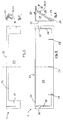
- Fig. 1 the cover designated as a whole with 1 in the connection area of two supply lines 2, 3 with two associated branch lines 4, 5 is shown, for example Form risers for radiators.
- a laying channel 8 formed by a retaining strip 6 on the wall and a cover strip 7 attached to it has a through opening 9 in the region of the cover strip 7, which opening is closed by the cover 1.
- the branch lines 4, 5 are connected to the supply line 2 via connections 10 or 11 or 18 and branch pipe connections 12, 15, which are connected to the supply lines 2, 3 by means of fittings 13, 14, 16, 17.
- the supply line 3 has a simple branch pipe connection 15 and the supply line 2 has a double branch pipe connection 12.
- the cover 1 is provided with a cover 19 which leaves a passage for the branch lines 4, 5 connected to the connections 10 and 18 and expediently covers the connection 11 which is not required.
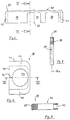
- the cover 1 shown in more detail in FIGS. 2 to 5 has a shaped recess 21 in an upper through wall 20, into which the cover 19 can be inserted.
- the cover 1 In the area of its vertical front wall 22 (FIG. 3), the cover 1 is provided on the inside with locking projections 23, 24, 25, which can be locked with a profile recess 26 (FIG. 4) in the edge region of the through opening 9 on the cover strip 8.
- the cover 1 has side end walls 27, 28 with an oblique edge 29 (FIG. 4) which can be supported flush on the cover strip 7.
- locking projections 30, 31 with a shaped recess 32 are provided in the region of the end walls 27, 28 that can be connected to the cover strip 7.
- the cover panel 19, which is illustrated in more detail in FIGS. 6 and 7, has an outer contour 33 which conforms to the shaped recess 21 of the covering hood 1 and has a receiving groove 35 which extends along the entire connection area and into which the edge 34 of the shaped recess 21 of the covering hood 1 can engage (FIG . 7).
- the cover panel 19 has a receiving opening 37 arranged symmetrically to a transverse center plane 36 and an outer receiving opening 38, into each of which a tubular panel 39 (FIG. 8) can be inserted.
- This arrangement of the receiving openings 37, 38 enables the cover panel 19 to be used differently, since it can be used in two operating positions rotated by 180 ° about its transverse central plane 36.
- the cover panel is designed symmetrically to its longitudinal center plane 36a.
- the receiving groove 35 can have a depth of engagement which enables the cover 19 to be displaced in the shaped recess 21 of the cover 1.
- the pipe diaphragm 39 illustrated in more detail in FIGS. 8 and 9 is formed with an outer contour 43 conforming to the receiving opening 37, 38 of the cover panel 19 and can be inserted in the connection area at the edge into a receiving groove 42 in the edge of the receiving opening 37 or 38.
- the pipe screen 39 can also be designed as an insert plate which overlaps the receiving openings 37, 38 on the edge.
- the pipe screen 39 has a central bore 44 which is adapted to the diameter of the branch pipes, wherein a monthly slot 46 running from the bore 44 to the rear edge 45 can be provided, which allows the pipe screen 39 to be placed on the wiring harness.
- the pipe screen 39 is similar to the cover 19 in the edge areas 47,48 of the receiving groove 42 dimensioned in such a way that a shift that is adaptable to the mounting conditions is possible.
Landscapes
- Engineering & Computer Science (AREA)
- Architecture (AREA)
- Civil Engineering (AREA)
- Structural Engineering (AREA)
- Protection Of Pipes Against Damage, Friction, And Corrosion (AREA)
- Crystals, And After-Treatments Of Crystals (AREA)
- Magnetic Resonance Imaging Apparatus (AREA)
- Light Receiving Elements (AREA)
- Duct Arrangements (AREA)
- Supports For Pipes And Cables (AREA)
- Rigid Pipes And Flexible Pipes (AREA)
- Details Of Indoor Wiring (AREA)
Applications Claiming Priority (2)
| Application Number | Priority Date | Filing Date | Title |
|---|---|---|---|
| DE9103265U | 1991-03-18 | ||
| DE9103265U DE9103265U1 (de) | 1991-03-18 | 1991-03-18 | Installationskanal |
Publications (2)
| Publication Number | Publication Date |
|---|---|
| EP0504497A1 true EP0504497A1 (fr) | 1992-09-23 |
| EP0504497B1 EP0504497B1 (fr) | 1994-12-07 |
Family
ID=6865376
Family Applications (1)
| Application Number | Title | Priority Date | Filing Date |
|---|---|---|---|
| EP91122247A Expired - Lifetime EP0504497B1 (fr) | 1991-03-18 | 1991-12-27 | Canal d'installation |
Country Status (6)
| Country | Link |
|---|---|
| US (1) | US5214888A (fr) |
| EP (1) | EP0504497B1 (fr) |
| AT (1) | ATE115227T1 (fr) |
| CA (1) | CA2062869A1 (fr) |
| DE (2) | DE9103265U1 (fr) |
| PT (1) | PT8918U (fr) |
Families Citing this family (2)
| Publication number | Priority date | Publication date | Assignee | Title |
|---|---|---|---|---|
| US5471804A (en) * | 1988-11-21 | 1995-12-05 | Winter, Iv; Amos G. | Building system using prefabricated building panels and fastening components used therewith |
| CN103322303B (zh) * | 2013-06-29 | 2015-05-13 | 王利彬 | 一种多功能大流量控制阀的安装结构 |
Citations (6)
| Publication number | Priority date | Publication date | Assignee | Title |
|---|---|---|---|---|
| DE650275C (de) * | 1936-03-14 | 1937-09-18 | Bayerische Flugzeugwerke Akt G | Verlegung von elektrischen Leitungskabeln in Kanaelen, insbesondere fuer Fahr- und Flugzeuge |
| US2161492A (en) * | 1928-08-21 | 1939-06-06 | Wadsworth Electric Mfg Co | Means for bank switch installations |
| DE2458311A1 (de) * | 1974-12-10 | 1976-06-16 | Friedhelm H Timpert | Sockelleiste zur aufnahme von wasserfuehrenden rohrleitungen oder elektrischen kabeln |
| GB1562566A (en) * | 1976-11-12 | 1980-03-12 | British Steel Corp | Multiple service module for dwellings |
| GB2197003A (en) * | 1986-10-21 | 1988-05-11 | Stephen John Clark | Wall outlet for tubes |
| EP0402025A2 (fr) * | 1989-06-06 | 1990-12-12 | Naka Corporation | Couvercle pour couvrir des ouvertures dans des panneaux de sols |
Family Cites Families (14)
| Publication number | Priority date | Publication date | Assignee | Title |
|---|---|---|---|---|
| FR1177110A (fr) * | 1957-05-29 | 1959-04-21 | Seine Const Elec | Gouttière de câblage |
| US3255563A (en) * | 1962-12-20 | 1966-06-14 | Victor E Sauer | Wall structure and support assembly |
| GB1160883A (en) * | 1965-10-27 | 1969-08-06 | F C Blackwell & Company Ltd | Wiring Section for an Electrical Wiring System |
| CH523607A (it) * | 1970-04-13 | 1972-05-31 | Bassani Spa | Canale per l'installazione di conduttori e tubi |
| DE2060093A1 (de) * | 1970-12-07 | 1972-06-29 | Oberweimar Elektroinstallation | Abzweig- oder Kreuzungseinrichtung fuer Fuss- und Wandleistenkanalinstallation |
| DE2408095A1 (de) * | 1974-02-20 | 1975-08-28 | Gerhard Neumann | Kabelverlegungskanal |
| US4135337A (en) * | 1977-09-12 | 1979-01-23 | Medlin Lewis B | Mounting means for electric outlet box |
| US4163572A (en) * | 1977-11-07 | 1979-08-07 | Textron Inc. | Transition fitting |
| FR2417197A1 (fr) * | 1978-02-09 | 1979-09-07 | Doncieux Rene | Conduit support semi-ferme |
| DE7811766U1 (de) * | 1978-04-19 | 1978-08-03 | Fa. Hermann Kleinhuis, 5880 Luedenscheid | Installationskanal zur verdeckten Verlegung elektrischer Kabel |
| NL7900898A (nl) * | 1979-02-05 | 1980-08-07 | Maars S A R L | Inrichting voor het koppelen van twee stroomrails. |
| DE3014695A1 (de) * | 1980-04-16 | 1981-10-22 | Tehalit Kunststoffwerk Gmbh, 6751 Heltersberg | Verdrahtungskanal |
| GB8907896D0 (en) * | 1989-04-07 | 1989-05-24 | Elecktrak International Limite | Trunking assembly |
| DE8904316U1 (de) * | 1989-04-07 | 1989-06-08 | Niedax GmbH + Co KG Gesellschaft für Verlegungsmaterial, 5460 Linz | Installationskanal mit U-Querschnitt und plattenförmiger Abdeckung |
-
1991
- 1991-03-18 DE DE9103265U patent/DE9103265U1/de not_active Expired - Lifetime
- 1991-12-27 DE DE59103811T patent/DE59103811D1/de not_active Expired - Fee Related
- 1991-12-27 EP EP91122247A patent/EP0504497B1/fr not_active Expired - Lifetime
- 1991-12-27 AT AT91122247T patent/ATE115227T1/de not_active IP Right Cessation
-
1992
- 1992-03-12 CA CA002062869A patent/CA2062869A1/fr not_active Abandoned
- 1992-03-13 US US07/850,749 patent/US5214888A/en not_active Expired - Fee Related
-
1993
- 1993-10-15 PT PT8918U patent/PT8918U/pt not_active IP Right Cessation
Patent Citations (6)
| Publication number | Priority date | Publication date | Assignee | Title |
|---|---|---|---|---|
| US2161492A (en) * | 1928-08-21 | 1939-06-06 | Wadsworth Electric Mfg Co | Means for bank switch installations |
| DE650275C (de) * | 1936-03-14 | 1937-09-18 | Bayerische Flugzeugwerke Akt G | Verlegung von elektrischen Leitungskabeln in Kanaelen, insbesondere fuer Fahr- und Flugzeuge |
| DE2458311A1 (de) * | 1974-12-10 | 1976-06-16 | Friedhelm H Timpert | Sockelleiste zur aufnahme von wasserfuehrenden rohrleitungen oder elektrischen kabeln |
| GB1562566A (en) * | 1976-11-12 | 1980-03-12 | British Steel Corp | Multiple service module for dwellings |
| GB2197003A (en) * | 1986-10-21 | 1988-05-11 | Stephen John Clark | Wall outlet for tubes |
| EP0402025A2 (fr) * | 1989-06-06 | 1990-12-12 | Naka Corporation | Couvercle pour couvrir des ouvertures dans des panneaux de sols |
Also Published As
| Publication number | Publication date |
|---|---|
| CA2062869A1 (fr) | 1992-09-19 |
| US5214888A (en) | 1993-06-01 |
| PT8918T (pt) | 1994-04-29 |
| PT8918U (pt) | 1996-12-31 |
| DE9103265U1 (de) | 1991-06-20 |
| EP0504497B1 (fr) | 1994-12-07 |
| ATE115227T1 (de) | 1994-12-15 |
| DE59103811D1 (de) | 1995-01-19 |
Similar Documents
| Publication | Publication Date | Title |
|---|---|---|
| DE10057122B4 (de) | Kabelkanalsystem mit getrennten Leitungen für Stromleiter und Datenübertragungsleiter | |
| DE19728708A1 (de) | Anordnung zum Einbau eines Kabelbaums in eine Automobiltür | |
| EP2196584A1 (fr) | Distributeur pour une installation de conduite d'eau | |
| DE9315970U1 (de) | Anordnung zum Verschließen einer Öffnung in einem Gehäuse | |
| EP0504497B1 (fr) | Canal d'installation | |
| DE4231049C2 (de) | Kabel- und Leitungskanal | |
| EP3055463B1 (fr) | Dispositif permettant le raccordement de robinetteries sanitaires | |
| EP0277344B1 (fr) | Canaux d'assemblage pour conduits | |
| WO2021156048A1 (fr) | Bague de câble | |
| DE3519763A1 (de) | Sanitaerarmaturenanschlussstueck | |
| DE3741830C2 (fr) | ||
| EP0980170A2 (fr) | Dispositif de porte, spécialement interphone | |
| EP0617246B1 (fr) | Appareil de commande et de régulation | |
| DE19620082C2 (de) | Kabelverzweigerschrank | |
| DE3014241A1 (de) | Vorrichtung zum verbinden von leuchten zu lichtbaendern bzw. lichtbandfiguren | |
| DE19536456A1 (de) | Gehäusedichtung für Leitungsdurchführungsöffnungen | |
| DE2149810B2 (de) | Gepäckablage für Fahrzeuge, insbesondere Autobusse | |
| DE19811777C1 (de) | Kleingehäuse für den Wandanbau | |
| DE10160268B4 (de) | Halterung für Kabel und/oder Leitungen in einem Fahrzeug | |
| DE3434643C2 (fr) | ||
| DE3838698C2 (de) | Anordnung zur Kabelüberführung zwischen einer Tür und einem Türschacht in einer Fahrzeugkarosserie | |
| DE10146331B4 (de) | System zur gleichzeitigen Gehäuseteilverbindung Modulinstallation | |
| DE20104947U1 (de) | Duschtrennwand | |
| DE10353177B4 (de) | Rosette für Wasserarmaturen | |
| DE29817108U1 (de) | Installationssystem für Heizungsanlagen |
Legal Events
| Date | Code | Title | Description |
|---|---|---|---|
| PUAI | Public reference made under article 153(3) epc to a published international application that has entered the european phase |
Free format text: ORIGINAL CODE: 0009012 |
|
| AK | Designated contracting states |
Kind code of ref document: A1 Designated state(s): AT BE CH DE DK ES FR GB GR IT LI LU NL SE |
|
| 17P | Request for examination filed |
Effective date: 19921110 |
|
| 17Q | First examination report despatched |
Effective date: 19930826 |
|
| GRAA | (expected) grant |
Free format text: ORIGINAL CODE: 0009210 |
|
| AK | Designated contracting states |
Kind code of ref document: B1 Designated state(s): AT BE CH DE DK ES FR GB GR IT LI LU NL SE |
|
| PG25 | Lapsed in a contracting state [announced via postgrant information from national office to epo] |
Ref country code: IT Free format text: LAPSE BECAUSE OF FAILURE TO SUBMIT A TRANSLATION OF THE DESCRIPTION OR TO PAY THE FEE WITHIN THE PRE;WARNING: LAPSES OF ITALIAN PATENTS WITH EFFECTIVE DATE BEFORE 2007 MAY HAVE OCCURRED AT ANY TIME BEFORE 2007. THE CORRECT EFFECTIVE DATE MAY BE DIFFERENT FROM THE ONE RECORDED.SCRIBED TIME-LIMIT Effective date: 19941207 Ref country code: DK Effective date: 19941207 Ref country code: BE Effective date: 19941207 Ref country code: NL Effective date: 19941207 Ref country code: GB Effective date: 19941207 Ref country code: GR Free format text: LAPSE BECAUSE OF FAILURE TO SUBMIT A TRANSLATION OF THE DESCRIPTION OR TO PAY THE FEE WITHIN THE PRESCRIBED TIME-LIMIT Effective date: 19941207 Ref country code: ES Free format text: THE PATENT HAS BEEN ANNULLED BY A DECISION OF A NATIONAL AUTHORITY Effective date: 19941207 Ref country code: FR Effective date: 19941207 |
|
| REF | Corresponds to: |
Ref document number: 115227 Country of ref document: AT Date of ref document: 19941215 Kind code of ref document: T |
|
| PG25 | Lapsed in a contracting state [announced via postgrant information from national office to epo] |
Ref country code: AT Effective date: 19941227 |
|
| PG25 | Lapsed in a contracting state [announced via postgrant information from national office to epo] |
Ref country code: LU Free format text: LAPSE BECAUSE OF NON-PAYMENT OF DUE FEES Effective date: 19941231 Ref country code: CH Effective date: 19941231 Ref country code: LI Effective date: 19941231 |
|
| REF | Corresponds to: |
Ref document number: 59103811 Country of ref document: DE Date of ref document: 19950119 |
|
| PG25 | Lapsed in a contracting state [announced via postgrant information from national office to epo] |
Ref country code: SE Effective date: 19950307 |
|
| EN | Fr: translation not filed | ||
| NLV1 | Nl: lapsed or annulled due to failure to fulfill the requirements of art. 29p and 29m of the patents act | ||
| GBV | Gb: ep patent (uk) treated as always having been void in accordance with gb section 77(7)/1977 [no translation filed] |
Effective date: 19941207 |
|
| REG | Reference to a national code |
Ref country code: CH Ref legal event code: PL |
|
| PLBE | No opposition filed within time limit |
Free format text: ORIGINAL CODE: 0009261 |
|
| STAA | Information on the status of an ep patent application or granted ep patent |
Free format text: STATUS: NO OPPOSITION FILED WITHIN TIME LIMIT |
|
| 26N | No opposition filed | ||
| PGFP | Annual fee paid to national office [announced via postgrant information from national office to epo] |
Ref country code: DE Payment date: 19980128 Year of fee payment: 7 |
|
| PG25 | Lapsed in a contracting state [announced via postgrant information from national office to epo] |
Ref country code: DE Free format text: LAPSE BECAUSE OF NON-PAYMENT OF DUE FEES Effective date: 19991001 |