EP0504497B1 - Canal d'installation - Google Patents
Canal d'installation Download PDFInfo
- Publication number
- EP0504497B1 EP0504497B1 EP91122247A EP91122247A EP0504497B1 EP 0504497 B1 EP0504497 B1 EP 0504497B1 EP 91122247 A EP91122247 A EP 91122247A EP 91122247 A EP91122247 A EP 91122247A EP 0504497 B1 EP0504497 B1 EP 0504497B1
- Authority
- EP
- European Patent Office
- Prior art keywords
- duct according
- installation duct
- cover
- pipe
- covering
- Prior art date
- Legal status (The legal status is an assumption and is not a legal conclusion. Google has not performed a legal analysis and makes no representation as to the accuracy of the status listed.)
- Expired - Lifetime
Links
- 238000009434 installation Methods 0.000 title claims abstract description 28
- 230000006978 adaptation Effects 0.000 claims 1
- 238000006073 displacement reaction Methods 0.000 claims 1
- 238000005253 cladding Methods 0.000 description 1
- 238000010438 heat treatment Methods 0.000 description 1
Images


Classifications
-
- H—ELECTRICITY
- H02—GENERATION; CONVERSION OR DISTRIBUTION OF ELECTRIC POWER
- H02G—INSTALLATION OF ELECTRIC CABLES OR LINES, OR OF COMBINED OPTICAL AND ELECTRIC CABLES OR LINES
- H02G11/00—Arrangements of electric cables or lines between relatively-movable parts
- H02G11/006—Arrangements of electric cables or lines between relatively-movable parts using extensible carrier for the cable, e.g. self-coiling spring
-
- E—FIXED CONSTRUCTIONS
- E04—BUILDING
- E04F—FINISHING WORK ON BUILDINGS, e.g. STAIRS, FLOORS
- E04F17/00—Vertical ducts; Channels, e.g. for drainage
- E04F17/08—Vertical ducts; Channels, e.g. for drainage for receiving utility lines, e.g. cables, pipes
-
- E—FIXED CONSTRUCTIONS
- E04—BUILDING
- E04F—FINISHING WORK ON BUILDINGS, e.g. STAIRS, FLOORS
- E04F19/00—Other details of constructional parts for finishing work on buildings
- E04F19/08—Built-in cupboards; Masks of niches; Covers of holes enabling access to installations
-
- H—ELECTRICITY
- H02—GENERATION; CONVERSION OR DISTRIBUTION OF ELECTRIC POWER
- H02G—INSTALLATION OF ELECTRIC CABLES OR LINES, OR OF COMBINED OPTICAL AND ELECTRIC CABLES OR LINES
- H02G3/00—Installations of electric cables or lines or protective tubing therefor in or on buildings, equivalent structures or vehicles
- H02G3/02—Details
- H02G3/04—Protective tubing or conduits, e.g. cable ladders or cable troughs
- H02G3/0437—Channels
Definitions
- the invention relates to an installation duct for supply lines, in particular for two-pipe installations, according to the preamble of claim 1.
- the object of the invention is to improve it in the area of branch lines in such a way that it can be adapted to different branch lines and different line spacings with little effort, and at the same time offers a visually appealing appearance.
- the invention provides for an installation channel a particularly easily mountable cover hood, which can be placed as an accessory during installation on the upper through opening of the cover strip and adapted to different branch lines.
- the cover which can be combined flush with the cover strip, creates a visually uniform, moderate view that hides the connection elements and can be dismantled for later access with little effort.
- an end cover In a wall insert for pipe routing and cladding of heating pipes laid in a wall at an exit point (GB-A-2 197 003), an end cover is known which, depending on the installation conditions, is provided with one or more through openings for pipes.
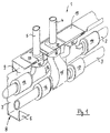
- Fig. 1 the cover designated as a whole with 1 in the connection area of two supply lines 2, 3 with two associated branch lines 4, 5 is shown, for example Form risers for radiators.
- a laying channel 8 formed by a retaining strip 6 on the wall and a cover strip 7 attached to it has a through opening 9 in the region of the cover strip 7, which opening is closed by the cover 1.
- the branch lines 4, 5 are connected to the supply line 2 via connections 10 or 11 or 18 and branch pipe connections 12, 15, which are connected to the supply lines 2, 3 by means of fittings 13, 14, 16, 17.
- the supply line 3 has a simple branch pipe connection 15 and the supply line 2 has a double branch pipe connection 12.
- the cover 1 is provided with a cover 19, which leaves a passage for the branch lines 4, 5 connected to the connections 10 and 18 and expediently covers the connection 11 which is not required.
- the cover 1 shown in more detail in FIGS. 2 to 5 has a shaped recess 21 in an upper lead-through wall 20, into which the cover 19 can be inserted.
- the cover 1 In the area of its vertical front wall 22 (FIG. 3), the cover 1 is provided on the inside with latching projections 23, 24, 25, which can be locked with a profile recess 26 (FIG. 4) in the edge region of the through opening 9 on the cover strip 7.
- the cover 1 has lateral end walls 27, 28 with an oblique edge 29 (FIG. 4) which can be supported flush on the cover strip 7.
- locking projections 30, 31 with a molded recess 32 are provided in the region of the end walls 27, 28 that can be connected to the cover strip 7.
- the cover panel 19, which is illustrated in more detail in FIGS. 6 and 7, has an outer contour 33 which conforms to the shaped recess 21 of the covering hood 1 and has a receiving groove 35 which extends along the entire connection area and into which the edge 34 of the shaped recess 21 of the covering hood 1 can engage (FIG 7).
- the cover panel 19 has a receiving opening 37 arranged symmetrically to a transverse center plane 36 and an outer receiving opening 38, into each of which a tubular panel 39 (FIG. 8) can be inserted.
- This arrangement of the receiving openings 37, 38 enables the cover panel 19 to be used differently, since it can be used in two operating positions rotated by 180 ° about its transverse central plane 36.
- the cover panel is designed symmetrically to its longitudinal center plane 36a.
- the receiving groove 35 can have a depth of engagement that enables the cover 19 to be displaced in the shaped recess 21 of the cover 1.
- the pipe screen 39 illustrated in more detail in FIGS. 8 and 9 is formed with an outer contour 43 conforming to the receiving opening 37, 38 of the cover screen 19 and can be inserted in the connecting area at the edge into a receiving groove 42 in the edge of the receiving opening 37 or 38.
- the pipe screen 39 can also be designed as an insert plate which overlaps the receiving openings 37, 38 on the edge.
- the pipe cover 39 has a central bore 44 which is adapted to the diameter of the branch lines, wherein a monthly slot 46 running from the bore 44 to the rear edge 45 can be provided, which allows the pipe cover 39 to be placed on the cable run.
- the pipe screen 39 is similar to the cover 19 in the edge areas 47,48 of the receiving groove 42 dimensioned in such a way that a shift that is adaptable to the mounting conditions is possible.
Landscapes
- Engineering & Computer Science (AREA)
- Architecture (AREA)
- Civil Engineering (AREA)
- Structural Engineering (AREA)
- Protection Of Pipes Against Damage, Friction, And Corrosion (AREA)
- Crystals, And After-Treatments Of Crystals (AREA)
- Magnetic Resonance Imaging Apparatus (AREA)
- Light Receiving Elements (AREA)
- Duct Arrangements (AREA)
- Supports For Pipes And Cables (AREA)
- Rigid Pipes And Flexible Pipes (AREA)
- Details Of Indoor Wiring (AREA)
Claims (15)
- Canal d'installation pour conduites d'alimentation, en particulier pour les installations à deux tuyaux, constitué par un profilé de maintien (6) du côté du mur et par un bandeau de recouvrement (7) pouvant y être fixé et qui présente dans sa zone supérieure une ouverture de passage (9) destinée à des conduites de branchement verticales (4, 5), caractérisé en ce que le bandeau de recouvrement (7) présente, dans la zone de l'ouverture de passage (9), un capot de recouvrement (1) qui, pour s'adapter à différentes liaisons de branchement (12, 15), présente une échancrure supérieure (21) dans laquelle peut être placé un cache de recouvrement (19) qui comprend plusieurs plaques de passage de tuyaux (39) qui sont montées chacune dans une ouverture de réception (37, 38) du cache de recouvrement (19) de façon à pouvoir être décalées.
- Canal d'installation suivant la revendication 1, caractérisé en ce que le capot de recouvrement (1) est pourvu, près de sa paroi verticale avant (22), du côté intérieur, de saillies d'arrêt (23, 24, 25) pouvant être amenées sur la partie périphérique de l'ouverture de passage (9) prévue dans le bandeau de recouvrement (7).
- Canal d'installation suivant la revendication 1 ou 2, caractérisé en ce que le capot de recouvrement (1) présente des parois terminales latérales (27, 28) qui sont réalisées avec des bords périphériques obliques (29).
- Canal d'installation suivant la revendication 3, caractérisé en ce que les parois terminales (27, 28) possèdent des saillies d'arrêt (30, 31) qui peuvent être reliées au bandeau de recouvrement (7).
- Canal d'installation suivant l'une quelconque des revendications 1 à 4, caractérisé en ce que le cache de recouvrement (19) présente un contour extérieur correspondant à l'échancrure (21) et une encoche de réception (35) dans laquelle est logé, tout au moins pour certaines parties, le bord (34) de l'échancrure (21) du capot de recouvrement (1).
- Canal d'installation suivant la revendication 5, caractérisé en ce que le cache de recouvrement (19) est pourvu d'au moins deux ouvertures de réception (37, 38) pour des plaques de passage de tuyaux (39).
- Canal d'installation suivant la revendication 5 ou 6, caractérisé en ce que l'une des ouvertures de réception (37) est placée symétriquement par rapport au plan médian transversal (36) du cache de recouvrement (19) et l'autre ouverture de réception (38) en est éloignée d'un pas d'écartement entre conduites de branchement (4, 5).
- Canal d'installation suivant l'une quelconque des revendications 5 à 7, caractérisé en ce que le cache de recouvrement (19) est symétrique par rapport à un plan médian longitudinal (36a) en vue de son montage dans deux positions de service différant l'une de l'autre par une rotation de 180°.
- Canal d'installation suivant l'une quelconque des revendications 5 à 8, caractérisé en ce que l'encoche de réception (35) présente une profondeur de prise qui permet de décaler le cache de recouvrement (19) dans l'échancrure (21).
- Canal d'installation suivant l'une quelconque des revendications 1 à 9, caractérisé en ce que les plaques de passage de tuyaux (39) présentent un contour extérieur qui correspond aux ouvertures de réception (37, 38) du cache de recouvrement (19).
- Canal d'installation suivant la revendication 10, caractérisé en ce que les plaques de passage de tuyaux (39) présentent, du côté du bord, une encoche de réception (42) destinée au bord des ouvertures de réception (37, 38).
- Canal d'installation suivant la revendication 10, caractérisé en ce que les plaques de passage de tuyaux (39) sont réalisées sous la forme de plaques à insérer.
- Canal d'installation suivant l'une quelconque des revendications 10 à 12, caractérisé en ce que les plaques de passage de tuyaux (39) présentent un trou central (44) adapté au diamètre des conduites de branchement (4, 5).
- Canal d'installation suivant l'une quelconque des revendications 10 à 13, caractérisé en ce que les plaques de passage de tuyaux (39) présentent une fente de montage (46) qui va du trou (44) à un bord périphérique (45).
- Canal d'installation suivant l'une quelconque des revendications 1 à 14, caractérisé en ce que les conduites de branchement (4, 5) présentent des éléments de raccordement (10, 11, 18) qui font saillie dans l'espace du capot de recouvrement (1).
Applications Claiming Priority (2)
| Application Number | Priority Date | Filing Date | Title |
|---|---|---|---|
| DE9103265U | 1991-03-18 | ||
| DE9103265U DE9103265U1 (de) | 1991-03-18 | 1991-03-18 | Installationskanal |
Publications (2)
| Publication Number | Publication Date |
|---|---|
| EP0504497A1 EP0504497A1 (fr) | 1992-09-23 |
| EP0504497B1 true EP0504497B1 (fr) | 1994-12-07 |
Family
ID=6865376
Family Applications (1)
| Application Number | Title | Priority Date | Filing Date |
|---|---|---|---|
| EP91122247A Expired - Lifetime EP0504497B1 (fr) | 1991-03-18 | 1991-12-27 | Canal d'installation |
Country Status (6)
| Country | Link |
|---|---|
| US (1) | US5214888A (fr) |
| EP (1) | EP0504497B1 (fr) |
| AT (1) | ATE115227T1 (fr) |
| CA (1) | CA2062869A1 (fr) |
| DE (2) | DE9103265U1 (fr) |
| PT (1) | PT8918U (fr) |
Families Citing this family (2)
| Publication number | Priority date | Publication date | Assignee | Title |
|---|---|---|---|---|
| US5471804A (en) * | 1988-11-21 | 1995-12-05 | Winter, Iv; Amos G. | Building system using prefabricated building panels and fastening components used therewith |
| CN103322303B (zh) * | 2013-06-29 | 2015-05-13 | 王利彬 | 一种多功能大流量控制阀的安装结构 |
Family Cites Families (20)
| Publication number | Priority date | Publication date | Assignee | Title |
|---|---|---|---|---|
| US2161492A (en) * | 1928-08-21 | 1939-06-06 | Wadsworth Electric Mfg Co | Means for bank switch installations |
| DE650275C (de) * | 1936-03-14 | 1937-09-18 | Bayerische Flugzeugwerke Akt G | Verlegung von elektrischen Leitungskabeln in Kanaelen, insbesondere fuer Fahr- und Flugzeuge |
| FR1177110A (fr) * | 1957-05-29 | 1959-04-21 | Seine Const Elec | Gouttière de câblage |
| US3255563A (en) * | 1962-12-20 | 1966-06-14 | Victor E Sauer | Wall structure and support assembly |
| GB1160883A (en) * | 1965-10-27 | 1969-08-06 | F C Blackwell & Company Ltd | Wiring Section for an Electrical Wiring System |
| CH523607A (it) * | 1970-04-13 | 1972-05-31 | Bassani Spa | Canale per l'installazione di conduttori e tubi |
| DE2060093A1 (de) * | 1970-12-07 | 1972-06-29 | Oberweimar Elektroinstallation | Abzweig- oder Kreuzungseinrichtung fuer Fuss- und Wandleistenkanalinstallation |
| DE2408095A1 (de) * | 1974-02-20 | 1975-08-28 | Gerhard Neumann | Kabelverlegungskanal |
| DE2458311B2 (de) * | 1974-12-10 | 1976-11-04 | Timpert, Friedhelm H., 3140 Lüneburg | Sockelleiste zur aufnahme von wasserfuehrenden rohrleitungen oder elektrischen kabeln |
| GB1562566A (en) * | 1976-11-12 | 1980-03-12 | British Steel Corp | Multiple service module for dwellings |
| US4135337A (en) * | 1977-09-12 | 1979-01-23 | Medlin Lewis B | Mounting means for electric outlet box |
| US4163572A (en) * | 1977-11-07 | 1979-08-07 | Textron Inc. | Transition fitting |
| FR2417197A1 (fr) * | 1978-02-09 | 1979-09-07 | Doncieux Rene | Conduit support semi-ferme |
| DE7811766U1 (de) * | 1978-04-19 | 1978-08-03 | Fa. Hermann Kleinhuis, 5880 Luedenscheid | Installationskanal zur verdeckten Verlegung elektrischer Kabel |
| NL7900898A (nl) * | 1979-02-05 | 1980-08-07 | Maars S A R L | Inrichting voor het koppelen van twee stroomrails. |
| DE3014695A1 (de) * | 1980-04-16 | 1981-10-22 | Tehalit Kunststoffwerk Gmbh, 6751 Heltersberg | Verdrahtungskanal |
| GB8625242D0 (en) * | 1986-10-21 | 1986-11-26 | Clark S J | Wall outlet system for central heating tubes |
| GB8907896D0 (en) * | 1989-04-07 | 1989-05-24 | Elecktrak International Limite | Trunking assembly |
| DE8904316U1 (de) * | 1989-04-07 | 1989-06-08 | Niedax GmbH + Co KG Gesellschaft für Verlegungsmaterial, 5460 Linz | Installationskanal mit U-Querschnitt und plattenförmiger Abdeckung |
| JPH0311912A (ja) * | 1989-06-06 | 1991-01-21 | Naka Tech Lab | フロアパネル開口部の塞ぎ板 |
-
1991
- 1991-03-18 DE DE9103265U patent/DE9103265U1/de not_active Expired - Lifetime
- 1991-12-27 DE DE59103811T patent/DE59103811D1/de not_active Expired - Fee Related
- 1991-12-27 EP EP91122247A patent/EP0504497B1/fr not_active Expired - Lifetime
- 1991-12-27 AT AT91122247T patent/ATE115227T1/de not_active IP Right Cessation
-
1992
- 1992-03-12 CA CA002062869A patent/CA2062869A1/fr not_active Abandoned
- 1992-03-13 US US07/850,749 patent/US5214888A/en not_active Expired - Fee Related
-
1993
- 1993-10-15 PT PT8918U patent/PT8918U/pt not_active IP Right Cessation
Also Published As
| Publication number | Publication date |
|---|---|
| CA2062869A1 (fr) | 1992-09-19 |
| US5214888A (en) | 1993-06-01 |
| PT8918T (pt) | 1994-04-29 |
| PT8918U (pt) | 1996-12-31 |
| EP0504497A1 (fr) | 1992-09-23 |
| DE9103265U1 (de) | 1991-06-20 |
| ATE115227T1 (de) | 1994-12-15 |
| DE59103811D1 (de) | 1995-01-19 |
Similar Documents
| Publication | Publication Date | Title |
|---|---|---|
| DE10057122B4 (de) | Kabelkanalsystem mit getrennten Leitungen für Stromleiter und Datenübertragungsleiter | |
| DE19811714C2 (de) | Bausatz für einen Schaltschrank | |
| DE2145453A1 (de) | Tisch mit einer Anordnung zum Aufnehmen von Geräteanschlußkabeln | |
| DE19728708C2 (de) | Anordnung zum Einbau eines Kabelbaums in eine Automobiltür | |
| EP0504497A1 (fr) | Canal d'installation | |
| EP0277344B1 (fr) | Canaux d'assemblage pour conduits | |
| DE3741830C2 (fr) | ||
| EP0617246B1 (fr) | Appareil de commande et de régulation | |
| DE102016207179B3 (de) | Kraftfahrzeug-Tür und Türgriffsystem hierfür | |
| DE8915226U1 (de) | Kabelkanal | |
| DE19620082C2 (de) | Kabelverzweigerschrank | |
| DE19811712C1 (de) | Schaltschrank | |
| DE3014241A1 (de) | Vorrichtung zum verbinden von leuchten zu lichtbaendern bzw. lichtbandfiguren | |
| DE19811777C1 (de) | Kleingehäuse für den Wandanbau | |
| DE10160268B4 (de) | Halterung für Kabel und/oder Leitungen in einem Fahrzeug | |
| DE2149810B2 (de) | Gepäckablage für Fahrzeuge, insbesondere Autobusse | |
| EP0952649A1 (fr) | Armoire de distribution avec boîtier intérieur pour blindage HF | |
| EP3217497B1 (fr) | Support d'appareil | |
| DE3434643C2 (fr) | ||
| EP0673096B1 (fr) | Boíte de distribution à basse tension ayant un espace libre pour le câblage | |
| DE9416322U1 (de) | Verbindungseinheit einer Aufnahme- und Befestigungseinrichtung für Profilschienen | |
| DE20104947U1 (de) | Duschtrennwand | |
| DE10112000C1 (de) | Geräteschrank | |
| DE29817108U1 (de) | Installationssystem für Heizungsanlagen | |
| DE19904949C1 (de) | Abgangsschienenträger zum Einbau in eine elektrische Verteilanlage |
Legal Events
| Date | Code | Title | Description |
|---|---|---|---|
| PUAI | Public reference made under article 153(3) epc to a published international application that has entered the european phase |
Free format text: ORIGINAL CODE: 0009012 |
|
| AK | Designated contracting states |
Kind code of ref document: A1 Designated state(s): AT BE CH DE DK ES FR GB GR IT LI LU NL SE |
|
| 17P | Request for examination filed |
Effective date: 19921110 |
|
| 17Q | First examination report despatched |
Effective date: 19930826 |
|
| GRAA | (expected) grant |
Free format text: ORIGINAL CODE: 0009210 |
|
| AK | Designated contracting states |
Kind code of ref document: B1 Designated state(s): AT BE CH DE DK ES FR GB GR IT LI LU NL SE |
|
| PG25 | Lapsed in a contracting state [announced via postgrant information from national office to epo] |
Ref country code: IT Free format text: LAPSE BECAUSE OF FAILURE TO SUBMIT A TRANSLATION OF THE DESCRIPTION OR TO PAY THE FEE WITHIN THE PRE;WARNING: LAPSES OF ITALIAN PATENTS WITH EFFECTIVE DATE BEFORE 2007 MAY HAVE OCCURRED AT ANY TIME BEFORE 2007. THE CORRECT EFFECTIVE DATE MAY BE DIFFERENT FROM THE ONE RECORDED.SCRIBED TIME-LIMIT Effective date: 19941207 Ref country code: DK Effective date: 19941207 Ref country code: BE Effective date: 19941207 Ref country code: NL Effective date: 19941207 Ref country code: GB Effective date: 19941207 Ref country code: GR Free format text: LAPSE BECAUSE OF FAILURE TO SUBMIT A TRANSLATION OF THE DESCRIPTION OR TO PAY THE FEE WITHIN THE PRESCRIBED TIME-LIMIT Effective date: 19941207 Ref country code: ES Free format text: THE PATENT HAS BEEN ANNULLED BY A DECISION OF A NATIONAL AUTHORITY Effective date: 19941207 Ref country code: FR Effective date: 19941207 |
|
| REF | Corresponds to: |
Ref document number: 115227 Country of ref document: AT Date of ref document: 19941215 Kind code of ref document: T |
|
| PG25 | Lapsed in a contracting state [announced via postgrant information from national office to epo] |
Ref country code: AT Effective date: 19941227 |
|
| PG25 | Lapsed in a contracting state [announced via postgrant information from national office to epo] |
Ref country code: LU Free format text: LAPSE BECAUSE OF NON-PAYMENT OF DUE FEES Effective date: 19941231 Ref country code: CH Effective date: 19941231 Ref country code: LI Effective date: 19941231 |
|
| REF | Corresponds to: |
Ref document number: 59103811 Country of ref document: DE Date of ref document: 19950119 |
|
| PG25 | Lapsed in a contracting state [announced via postgrant information from national office to epo] |
Ref country code: SE Effective date: 19950307 |
|
| EN | Fr: translation not filed | ||
| NLV1 | Nl: lapsed or annulled due to failure to fulfill the requirements of art. 29p and 29m of the patents act | ||
| GBV | Gb: ep patent (uk) treated as always having been void in accordance with gb section 77(7)/1977 [no translation filed] |
Effective date: 19941207 |
|
| REG | Reference to a national code |
Ref country code: CH Ref legal event code: PL |
|
| PLBE | No opposition filed within time limit |
Free format text: ORIGINAL CODE: 0009261 |
|
| STAA | Information on the status of an ep patent application or granted ep patent |
Free format text: STATUS: NO OPPOSITION FILED WITHIN TIME LIMIT |
|
| 26N | No opposition filed | ||
| PGFP | Annual fee paid to national office [announced via postgrant information from national office to epo] |
Ref country code: DE Payment date: 19980128 Year of fee payment: 7 |
|
| PG25 | Lapsed in a contracting state [announced via postgrant information from national office to epo] |
Ref country code: DE Free format text: LAPSE BECAUSE OF NON-PAYMENT OF DUE FEES Effective date: 19991001 |