EP0504497A1 - Installationskanal - Google Patents
Installationskanal Download PDFInfo
- Publication number
- EP0504497A1 EP0504497A1 EP91122247A EP91122247A EP0504497A1 EP 0504497 A1 EP0504497 A1 EP 0504497A1 EP 91122247 A EP91122247 A EP 91122247A EP 91122247 A EP91122247 A EP 91122247A EP 0504497 A1 EP0504497 A1 EP 0504497A1
- Authority
- EP
- European Patent Office
- Prior art keywords
- cover
- duct according
- installation duct
- pipe
- installation
- Prior art date
- Legal status (The legal status is an assumption and is not a legal conclusion. Google has not performed a legal analysis and makes no representation as to the accuracy of the status listed.)
- Granted
Links
- 238000009434 installation Methods 0.000 title claims abstract description 30
Images

Classifications
-
- H—ELECTRICITY
- H02—GENERATION; CONVERSION OR DISTRIBUTION OF ELECTRIC POWER
- H02G—INSTALLATION OF ELECTRIC CABLES OR LINES, OR OF COMBINED OPTICAL AND ELECTRIC CABLES OR LINES
- H02G11/00—Arrangements of electric cables or lines between relatively-movable parts
- H02G11/006—Arrangements of electric cables or lines between relatively-movable parts using extensible carrier for the cable, e.g. self-coiling spring
-
- E—FIXED CONSTRUCTIONS
- E04—BUILDING
- E04F—FINISHING WORK ON BUILDINGS, e.g. STAIRS, FLOORS
- E04F17/00—Vertical ducts; Channels, e.g. for drainage
- E04F17/08—Vertical ducts; Channels, e.g. for drainage for receiving utility lines, e.g. cables, pipes
-
- E—FIXED CONSTRUCTIONS
- E04—BUILDING
- E04F—FINISHING WORK ON BUILDINGS, e.g. STAIRS, FLOORS
- E04F19/00—Other details of constructional parts for finishing work on buildings
- E04F19/08—Built-in cupboards; Masks of niches; Covers of holes enabling access to installations
-
- H—ELECTRICITY
- H02—GENERATION; CONVERSION OR DISTRIBUTION OF ELECTRIC POWER
- H02G—INSTALLATION OF ELECTRIC CABLES OR LINES, OR OF COMBINED OPTICAL AND ELECTRIC CABLES OR LINES
- H02G3/00—Installations of electric cables or lines or protective tubing therefor in or on buildings, equivalent structures or vehicles
- H02G3/02—Details
- H02G3/04—Protective tubing or conduits, e.g. cable ladders or cable troughs
- H02G3/0437—Channels
Definitions
- the invention relates to an installation duct for supply lines, in particular for two-pipe installations, according to the preamble of claim 1.
- the object of the invention is to improve it in the area of branch lines in such a way that it can be adapted to different branch lines and different line spacings with little effort and thereby a offers a visually appealing appearance.
- the invention provides a cover hood that is particularly easy to install at any point and that can be placed as an accessory during installation on the upper lead-through opening of the cover strip and can be adapted to different branch lines.
- the cover which can be combined flush with the cover strip, creates a visually uniform, the connection elements concealing view and can be dismantled for later access with little effort.
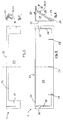
- Fig. 1 the cover designated as a whole with 1 in the connection area of two supply lines 2, 3 with two associated branch lines 4, 5 is shown, for example Form risers for radiators.
- a laying channel 8 formed by a retaining strip 6 on the wall and a cover strip 7 attached to it has a through opening 9 in the region of the cover strip 7, which opening is closed by the cover 1.
- the branch lines 4, 5 are connected to the supply line 2 via connections 10 or 11 or 18 and branch pipe connections 12, 15, which are connected to the supply lines 2, 3 by means of fittings 13, 14, 16, 17.
- the supply line 3 has a simple branch pipe connection 15 and the supply line 2 has a double branch pipe connection 12.
- the cover 1 is provided with a cover 19 which leaves a passage for the branch lines 4, 5 connected to the connections 10 and 18 and expediently covers the connection 11 which is not required.
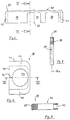
- the cover 1 shown in more detail in FIGS. 2 to 5 has a shaped recess 21 in an upper through wall 20, into which the cover 19 can be inserted.
- the cover 1 In the area of its vertical front wall 22 (FIG. 3), the cover 1 is provided on the inside with locking projections 23, 24, 25, which can be locked with a profile recess 26 (FIG. 4) in the edge region of the through opening 9 on the cover strip 8.
- the cover 1 has side end walls 27, 28 with an oblique edge 29 (FIG. 4) which can be supported flush on the cover strip 7.
- locking projections 30, 31 with a shaped recess 32 are provided in the region of the end walls 27, 28 that can be connected to the cover strip 7.
- the cover panel 19, which is illustrated in more detail in FIGS. 6 and 7, has an outer contour 33 which conforms to the shaped recess 21 of the covering hood 1 and has a receiving groove 35 which extends along the entire connection area and into which the edge 34 of the shaped recess 21 of the covering hood 1 can engage (FIG . 7).
- the cover panel 19 has a receiving opening 37 arranged symmetrically to a transverse center plane 36 and an outer receiving opening 38, into each of which a tubular panel 39 (FIG. 8) can be inserted.
- This arrangement of the receiving openings 37, 38 enables the cover panel 19 to be used differently, since it can be used in two operating positions rotated by 180 ° about its transverse central plane 36.
- the cover panel is designed symmetrically to its longitudinal center plane 36a.
- the receiving groove 35 can have a depth of engagement which enables the cover 19 to be displaced in the shaped recess 21 of the cover 1.
- the pipe diaphragm 39 illustrated in more detail in FIGS. 8 and 9 is formed with an outer contour 43 conforming to the receiving opening 37, 38 of the cover panel 19 and can be inserted in the connection area at the edge into a receiving groove 42 in the edge of the receiving opening 37 or 38.
- the pipe screen 39 can also be designed as an insert plate which overlaps the receiving openings 37, 38 on the edge.
- the pipe screen 39 has a central bore 44 which is adapted to the diameter of the branch pipes, wherein a monthly slot 46 running from the bore 44 to the rear edge 45 can be provided, which allows the pipe screen 39 to be placed on the wiring harness.
- the pipe screen 39 is similar to the cover 19 in the edge areas 47,48 of the receiving groove 42 dimensioned in such a way that a shift that is adaptable to the mounting conditions is possible.
Landscapes
- Engineering & Computer Science (AREA)
- Architecture (AREA)
- Civil Engineering (AREA)
- Structural Engineering (AREA)
- Protection Of Pipes Against Damage, Friction, And Corrosion (AREA)
- Crystals, And After-Treatments Of Crystals (AREA)
- Magnetic Resonance Imaging Apparatus (AREA)
- Light Receiving Elements (AREA)
- Duct Arrangements (AREA)
- Supports For Pipes And Cables (AREA)
- Rigid Pipes And Flexible Pipes (AREA)
- Details Of Indoor Wiring (AREA)
Abstract
Description
- Die Erfindung bezieht sich auf einen Installationskanal für Versorgungsleitungen, insbesondere für Zweirohrinstallationen, nach dem Oberbegriff des Anspruchs 1.
- Ausgehend von einem Installationskanal der vorstehend genannten, aus der DE-PS 24 58 311 bekannten Art liegt der Erfindung die Aufgabe zugrunde, diesen im Bereich von Zweigleitungen derart zu verbessern, daß er mit geringem Aufwand an unterschiedliche Zweigleitungen und unterschiedliche Leitungsabstände anpaßbar ist und dabei ein optisch ansprechendes Erscheinungsbild darbietet.
- Die Erfindung löst diese Aufgabe durch einen Installationskanal mit den Merkmalen des Anspruchs 1. Hinsichtlich wesentlicher weiterer Ausgestaltungen wird auf die Ansprüche 2 bis 17 verwiesen.
- Die Erfindung schafft für einen Installationskanal eine an beliebiger Stelle besonders einfach montierbare Abdeckhaube, die als Zubehörteil bei der Installation auf die obere Durchführöffnung der Abdeckleiste aufsetzbar und angepaßt an unterschiedliche Zweigleitungen verschließbar ist. Die mit der Abdeckleiste bündig vereinigbare Abdeckhaube schafft für den Anschlußbereich eine optisch gleichmäßige, die Anbindungselemente verdeckende Ansicht und ist mit geringem Aufwand für einen späteren Zugriff demontierbar.
- Hinsichtlich wesentlicher weiterer Vorteile und Einzelheiten der Erfindung wird auf die nachfolgende Beschreibung und die Zeichnung verwiesen, in der ein Ausführungsbeispiel des Gegenstandes der Erfindung schematisch näher veranschaulicht ist. In der Zeichnung zeigen:
- Fig. 1
- eine perspektivische, teilweise geschnittene Darstellung des erfindungsgemäßen Installationskanals mit zwei Versorgungsleitungen und zwei Zweigleitungen,
- Fig. 2
- eine Draufsicht auf eine erfindungsgemäße Abdeckhaube in Einzeldarstellung,
- Fig. 3
- eine Innenansicht der Abdeckhaube gemäß Fig. 2,
- Fig. 4
- eine Seitenansicht der Abdeckhaube gemäß Fig. 2 und 3,
- Fig. 5
- einen Schnitt durch die Abdeckhaube gemäß der Linie IV-IV in Fig. 4,
- Fig. 6
- eine Draufsicht auf eine Abdeckblende gemäß der Erfindung,
- Fig. 7
- einen Schnitt gemäß der Linie VI-VI in Fig. 6,
- Fig. 8
- eine Draufsicht auf eine erfindungsgemäße Rohrblende, und
- Fig. 9
- einen Schnitt gemäß der Linie VIII-VIII in Fig. 8.
- In Fig. 1 ist die als Ganzes mit 1 bezeichnete Abdeckhaube im Verbindungsbereich zweier Versorgungsleitungen 2,3 mit zwei zugeordneten Zweigleitungen 4,5 dargestellt, die beispielsweise Steigleitungen für Heizkörper bilden. Ein von einer wandseitigen Halteleiste 6 sowie einer daran befestigten Abdeckleiste 7 gebildeter Verlegekanal 8 weist dabei im Bereich der Abdeckleiste 7 eine Durchführöffnung 9 auf, die von der Abdeckhaube 1 verschlossen ist. An die Versorgungsleitung 2 sind die Zweigleitungen 4,5 über Anschlüsse 10 oder 11 bzw. 18 und Zweigrohranbindungen 12, 15 angeschlossen, die mittels Fittings 13,14,16,17 mit den Versorgungsleitungen 2,3 verbunden sind. Die Versorgungsleitung 3 weist dabei eine einfache Zweigrohranbindung 15 und die Versorgungsleitung 2 eine doppelte Zweigrohranbindung 12 auf. Die Abdeckhaube 1 ist mit einer Abdeckblende 19 versehen, die einen Durchgang für die mit den Anschlüssen 10 und 18 verbundenen Zweigleitungen 4,5 freiläßt und den nicht benötigten Anschluß 11 zweckmäßig abdeckt.
- Die in den Fig. 2 bis 5 näher dargestellte Abdeckhaube 1 weist in einer oberen Durchführwand 20 eine Formausnehmung 21 auf, in die die Abdeckblende 19 einsetzbar ist.
- Im Bereich ihrer senkrechten Vorderwand 22 (Fig. 3) ist die Abdeckhaube 1 innenseitig mit Rastansätzen 23,24,25 versehen, die mit einer Profilausnehmung 26 (Fig. 4) im Randbereich der Durchführöffnung 9 an der Abdeckleiste 8 verrastbar sind.
- Die Abdeckhaube 1 hat seitliche Abschlußwände 27,28 mit einer schrägen Randkante 29 (Fig. 4), die sich bündig auf der Abdeckleiste 7 abstützen kann. Zur Sicherung der Verbindung mit der Abdeckleiste 7 sind im Bereich der Abschlußwände 27,28 mit der Abdeckleiste 7 verbindbare Rastansätze 30,31 mit einer Formausnehmung 32 (Fig. 5) vorgesehen.
- Die in Fig. 6 und 7 näher veranschaulichte Abdeckblende 19 weist eine der Formausnehmung 21 der Abdeckhaube 1 konforme Außenkontur 33 auf und hat eine sich entlang dem gesamten Verbindungsbereich erstreckende Aufnahmenut 35, in die der Rand 34 der Formausnehmung 21 der Abdeckhaube 1 eingreifen kann (Fig. 7).
- Die Abdeckblende 19 weist eine symmetrisch zu einer Quermittelebene 36 angeordnete Aufnahmeöffnung 37 und eine äußere Aufnahmeöffnung 38 auf, in die jeweils eine Rohrblende 39 (Fig. 8) einsetzbar ist. Diese Anordnung der Aufnahmeöffnungen 37,38 ermöglicht einen unterschiedlichen Einsatz der Abdeckblende 19, da diese um ihre Quermittelebene 36 um 180° verdreht in zwei Betriebsstellungen verwendbar ist. Hierzu ist die Abdeckblende zu ihrer Längsmittelebene 36a symmetrisch ausgeführt.
- Die Aufnahmenut 35 kann in ihren seitlichen Bereichen 40,41 eine die Verschiebbarkeit der Abdeckblende 19 in der Formausnehmung 21 der Abdeckhaube 1 ermöglichende Eingriffstiefe aufweisen.
- Die in Fig. 8 und Fig. 9 näher veranschaulichte Rohrblende 39 ist mit einer der Aufnahmeöffnung 37,38 der Abdeckblende 19 konformen Außenkontur 43 ausgebildet und ist im Verbindungsbereich randseitig in eine Aufnahmenut 42 in den Rand der Aufnahmeöffnung 37 bzw. 38 einsetzbar. Die Rohrblende 39 kann in einfachster Ausführung auch als Einlegeplatte ausgebildet sein, die die Aufnahmeöffnungen 37, 38 randseitig übergreift.
- Für die Durchführung von Zweigleitungen weist die Rohrblende 39 eine an den Durchmesser der Zweigleitungen angepaßte mittige Bohrung 44 auf, wobei ein von der Bohrung 44 zur rückseitigen Randkante 45 verlaufender Monatageschlitz 46 vorgesehen sein kann, der ein Aufsetzen der Rohrblende 39 auf den Leitungsstrang erlaubt.
- Die Rohrblende 39 ist ähnlich der Abdeckblende 19 in randseitigen Bereichen 47,48 der Aufnahmenut 42 in der Nuttiefe derart bemessen, daß eine an Montagebedingungen anpaßbare Verschiebung möglich ist.
Claims (17)
- Installationskanal für Versorgungsleitungen, inbesondere für Zweirohrinstallationen, der von einer wandseitigen Halteleiste (6) sowie einer daran befestigbaren Abdeckleiste (7) gebildet ist, die für senkrechte Zweigleitungen (4,5) im oberen Bereich mit einer Durchführöffnung (9) versehbar ist, dadurch gekennzeichnet, daß die Abdeckleiste (7) im Bereich der Durchführöffnung (9) eine an unterschiedliche Zweigrohranbindungen (12,15) anpaßbare Abdeckhaube (1) aufweist.
- Installationskanal nach Anspruch 1, dadurch gekennzeichnet, daß die Abdeckhaube (1) eine obere Formausnehmung (21) aufweist, in die eine Abdeckblende (19) für die Zweigleitungen (4,5) mit mehreren Rohrblenden (39) einsetzbar ist.
- Installationskanal nach Anspruch 1 und 2, dadurch gekennzeichnet, daß die Abdeckhaube (1) im Bereich ihrer senkrechten Vorderwand (22) innenseitig mit auf den Randbereich der Durchführöffnung (9) in der Abdeckleiste (7) aufsetzbaren Rastansätzen (23,24,25) versehen ist.
- Installationskanal nach einem der Ansprüche 1 bis 3, dadurch gekennzeichnet, daß die Abdeckhaube (1) seitliche Abschlußwände (27,28) aufweist, die mit schrägen Randkanten (29) ausgebildet sind.
- Installationskanal nach Anspruch 4, dadurch gekennzeichnet, daß an den Abschlußwänden (27,28) mit der Abdeckleiste (7) verbindbare Rastansätze (30,31) ausgebildet sind.
- Installationskanal nach einem der Ansprüche 1 bis 5, dadurch gekennzeichnet, daß die Abdeckblende (19) eine der Formausnehmung (21) konforme Außenkontur und eine zumindest bereichsweise den Rand (34) der Formausnehmung (21) der Abdeckhaube (1) aufnehmenden Aufnahmenut (35) aufweist.
- Installationskanal nach Anspruch 6, dadurch gekennzeichnet, daß die Abdeckblende (19) mit zumindest zwei Aufnahmeöffnungen (37,38) für Rohrblenden (39) versehen ist.
- Installationskanal nach Anspruch 6 oder 7, dadurch gekennzeichnet, daß die eine Aufnahmeöffnung (37) symmetrisch zur Quermittelebene (36) der Abdeckblende (19) angeordnet und eine zweite Aufnahmeöffnung (38) um ein Abstandsmaß zwischen Zweigleitungen (4,5) beabstandet ist.
- Installationskanal nach einem der Ansprüche 6 bis 8, dadurch gekennzeichnet, daß die Abdeckblende (19) für den Einbau in zwei um 180° verdrehten Betriebsstellungen eine zu einer Längsmittelebene (36a) symmetrische Ausbildung aufweist.
- Installationskanal nach einem der Ansprüche 6 bis 9, dadurch gekennzeichnet, daß die Aufnahmenut (35) eine die Verschiebbarkeit der Abdeckblende (19) in der Formausnehmung (21) ermöglichende Eingriffstiefe aufweist.
- Installationskanal nach einem der Ansprüche 1 bis 10, dadurch gekennzeichnet, daß die Rohrblenden (39) mit einer den Aufnahmeöffnungen (37,38) der Abdeckblende (19) konformen Außenkontur versehen sind.
- Installationskanal nach Anspruch 11, dadurch gekennzeichnet, daß die Rohrblenden (39) randseitig mit einer Aufnahmenut (42) für den Rand der Aufnahmeöffnungen (37,38) versehen sind.
- Installationskanal nach Anspruch 11, dadurch gekennzeichnet, daß die Rohrblenden (39) als Einlegeplatte ausgebildet sind.
- Installationskanal nach einem der Ansprüche 11 oder 13, dadurch gekennzeichnet, daß die Rohrblenden (39) mit einer an den Durchmesser der Zweigleitungen (4,5) angepaßten mittigen Bohrung (44) versehen sind.
- Installationskanal nach einem der Ansprüche 11 bis 14, dadurch gekennzeichnet, daß die Rohrblenden (39) in den Aufnahmeöffnungen (37,38) der Abdeckblende (19) verschiebbar abgestützt sind.
- Installationskanal nach einem der Ansprüche 11 bis 15, dadurch gekennzeichnet, daß die Rohrblenden (39) einen von der Bohrung (44) zu einer Randkante (45) verlaufenden Montageschlitz (46) aufweisen.
- Installationskanal nach einem der Ansprüche 1 bis 16, dadurch gekennzeichnet, daß die Zweigleitungen (4,5) in den Bereich der Abdeckhaube (1) vorstehende Anbindungselemente (10,11,18) aufweisen.
Applications Claiming Priority (2)
| Application Number | Priority Date | Filing Date | Title |
|---|---|---|---|
| DE9103265U | 1991-03-18 | ||
| DE9103265U DE9103265U1 (de) | 1991-03-18 | 1991-03-18 | Installationskanal |
Publications (2)
| Publication Number | Publication Date |
|---|---|
| EP0504497A1 true EP0504497A1 (de) | 1992-09-23 |
| EP0504497B1 EP0504497B1 (de) | 1994-12-07 |
Family
ID=6865376
Family Applications (1)
| Application Number | Title | Priority Date | Filing Date |
|---|---|---|---|
| EP91122247A Expired - Lifetime EP0504497B1 (de) | 1991-03-18 | 1991-12-27 | Installationskanal |
Country Status (6)
| Country | Link |
|---|---|
| US (1) | US5214888A (de) |
| EP (1) | EP0504497B1 (de) |
| AT (1) | ATE115227T1 (de) |
| CA (1) | CA2062869A1 (de) |
| DE (2) | DE9103265U1 (de) |
| PT (1) | PT8918U (de) |
Families Citing this family (2)
| Publication number | Priority date | Publication date | Assignee | Title |
|---|---|---|---|---|
| US5471804A (en) * | 1988-11-21 | 1995-12-05 | Winter, Iv; Amos G. | Building system using prefabricated building panels and fastening components used therewith |
| CN103322303B (zh) * | 2013-06-29 | 2015-05-13 | 王利彬 | 一种多功能大流量控制阀的安装结构 |
Citations (6)
| Publication number | Priority date | Publication date | Assignee | Title |
|---|---|---|---|---|
| DE650275C (de) * | 1936-03-14 | 1937-09-18 | Bayerische Flugzeugwerke Akt G | Verlegung von elektrischen Leitungskabeln in Kanaelen, insbesondere fuer Fahr- und Flugzeuge |
| US2161492A (en) * | 1928-08-21 | 1939-06-06 | Wadsworth Electric Mfg Co | Means for bank switch installations |
| DE2458311A1 (de) * | 1974-12-10 | 1976-06-16 | Friedhelm H Timpert | Sockelleiste zur aufnahme von wasserfuehrenden rohrleitungen oder elektrischen kabeln |
| GB1562566A (en) * | 1976-11-12 | 1980-03-12 | British Steel Corp | Multiple service module for dwellings |
| GB2197003A (en) * | 1986-10-21 | 1988-05-11 | Stephen John Clark | Wall outlet for tubes |
| EP0402025A2 (de) * | 1989-06-06 | 1990-12-12 | Naka Corporation | Schliessplatte, um Öffnungen in Bodenplatten abzudecken |
Family Cites Families (14)
| Publication number | Priority date | Publication date | Assignee | Title |
|---|---|---|---|---|
| FR1177110A (fr) * | 1957-05-29 | 1959-04-21 | Seine Const Elec | Gouttière de câblage |
| US3255563A (en) * | 1962-12-20 | 1966-06-14 | Victor E Sauer | Wall structure and support assembly |
| GB1160883A (en) * | 1965-10-27 | 1969-08-06 | F C Blackwell & Company Ltd | Wiring Section for an Electrical Wiring System |
| CH523607A (it) * | 1970-04-13 | 1972-05-31 | Bassani Spa | Canale per l'installazione di conduttori e tubi |
| DE2060093A1 (de) * | 1970-12-07 | 1972-06-29 | Oberweimar Elektroinstallation | Abzweig- oder Kreuzungseinrichtung fuer Fuss- und Wandleistenkanalinstallation |
| DE2408095A1 (de) * | 1974-02-20 | 1975-08-28 | Gerhard Neumann | Kabelverlegungskanal |
| US4135337A (en) * | 1977-09-12 | 1979-01-23 | Medlin Lewis B | Mounting means for electric outlet box |
| US4163572A (en) * | 1977-11-07 | 1979-08-07 | Textron Inc. | Transition fitting |
| FR2417197A1 (fr) * | 1978-02-09 | 1979-09-07 | Doncieux Rene | Conduit support semi-ferme |
| DE7811766U1 (de) * | 1978-04-19 | 1978-08-03 | Fa. Hermann Kleinhuis, 5880 Luedenscheid | Installationskanal zur verdeckten Verlegung elektrischer Kabel |
| NL7900898A (nl) * | 1979-02-05 | 1980-08-07 | Maars S A R L | Inrichting voor het koppelen van twee stroomrails. |
| DE3014695A1 (de) * | 1980-04-16 | 1981-10-22 | Tehalit Kunststoffwerk Gmbh, 6751 Heltersberg | Verdrahtungskanal |
| GB8907896D0 (en) * | 1989-04-07 | 1989-05-24 | Elecktrak International Limite | Trunking assembly |
| DE8904316U1 (de) * | 1989-04-07 | 1989-06-08 | Niedax GmbH + Co KG Gesellschaft für Verlegungsmaterial, 5460 Linz | Installationskanal mit U-Querschnitt und plattenförmiger Abdeckung |
-
1991
- 1991-03-18 DE DE9103265U patent/DE9103265U1/de not_active Expired - Lifetime
- 1991-12-27 DE DE59103811T patent/DE59103811D1/de not_active Expired - Fee Related
- 1991-12-27 EP EP91122247A patent/EP0504497B1/de not_active Expired - Lifetime
- 1991-12-27 AT AT91122247T patent/ATE115227T1/de not_active IP Right Cessation
-
1992
- 1992-03-12 CA CA002062869A patent/CA2062869A1/en not_active Abandoned
- 1992-03-13 US US07/850,749 patent/US5214888A/en not_active Expired - Fee Related
-
1993
- 1993-10-15 PT PT8918U patent/PT8918U/pt not_active IP Right Cessation
Patent Citations (6)
| Publication number | Priority date | Publication date | Assignee | Title |
|---|---|---|---|---|
| US2161492A (en) * | 1928-08-21 | 1939-06-06 | Wadsworth Electric Mfg Co | Means for bank switch installations |
| DE650275C (de) * | 1936-03-14 | 1937-09-18 | Bayerische Flugzeugwerke Akt G | Verlegung von elektrischen Leitungskabeln in Kanaelen, insbesondere fuer Fahr- und Flugzeuge |
| DE2458311A1 (de) * | 1974-12-10 | 1976-06-16 | Friedhelm H Timpert | Sockelleiste zur aufnahme von wasserfuehrenden rohrleitungen oder elektrischen kabeln |
| GB1562566A (en) * | 1976-11-12 | 1980-03-12 | British Steel Corp | Multiple service module for dwellings |
| GB2197003A (en) * | 1986-10-21 | 1988-05-11 | Stephen John Clark | Wall outlet for tubes |
| EP0402025A2 (de) * | 1989-06-06 | 1990-12-12 | Naka Corporation | Schliessplatte, um Öffnungen in Bodenplatten abzudecken |
Also Published As
| Publication number | Publication date |
|---|---|
| CA2062869A1 (en) | 1992-09-19 |
| US5214888A (en) | 1993-06-01 |
| PT8918T (pt) | 1994-04-29 |
| PT8918U (pt) | 1996-12-31 |
| DE9103265U1 (de) | 1991-06-20 |
| EP0504497B1 (de) | 1994-12-07 |
| ATE115227T1 (de) | 1994-12-15 |
| DE59103811D1 (de) | 1995-01-19 |
Similar Documents
| Publication | Publication Date | Title |
|---|---|---|
| DE10057122B4 (de) | Kabelkanalsystem mit getrennten Leitungen für Stromleiter und Datenübertragungsleiter | |
| DE19728708A1 (de) | Anordnung zum Einbau eines Kabelbaums in eine Automobiltür | |
| EP2196584A1 (de) | Verteiler für eine Wasserleitungsanlage | |
| DE9315970U1 (de) | Anordnung zum Verschließen einer Öffnung in einem Gehäuse | |
| EP0504497B1 (de) | Installationskanal | |
| DE4231049C2 (de) | Kabel- und Leitungskanal | |
| EP3055463B1 (de) | Vorrichtung zum anschluss von sanitärarmaturen | |
| EP0277344B1 (de) | Anbaukanäle für Leitungen | |
| WO2021156048A1 (de) | Leitungsdurchführung | |
| DE3519763A1 (de) | Sanitaerarmaturenanschlussstueck | |
| DE3741830C2 (de) | ||
| EP0980170A2 (de) | Türanlage, insbesondere Türsprechanlage | |
| EP0617246B1 (de) | Regel- und Steuergerät | |
| DE19620082C2 (de) | Kabelverzweigerschrank | |
| DE3014241A1 (de) | Vorrichtung zum verbinden von leuchten zu lichtbaendern bzw. lichtbandfiguren | |
| DE19536456A1 (de) | Gehäusedichtung für Leitungsdurchführungsöffnungen | |
| DE2149810B2 (de) | Gepäckablage für Fahrzeuge, insbesondere Autobusse | |
| DE19811777C1 (de) | Kleingehäuse für den Wandanbau | |
| DE10160268B4 (de) | Halterung für Kabel und/oder Leitungen in einem Fahrzeug | |
| DE3434643C2 (de) | ||
| DE3838698C2 (de) | Anordnung zur Kabelüberführung zwischen einer Tür und einem Türschacht in einer Fahrzeugkarosserie | |
| DE10146331B4 (de) | System zur gleichzeitigen Gehäuseteilverbindung Modulinstallation | |
| DE20104947U1 (de) | Duschtrennwand | |
| DE10353177B4 (de) | Rosette für Wasserarmaturen | |
| DE29817108U1 (de) | Installationssystem für Heizungsanlagen |
Legal Events
| Date | Code | Title | Description |
|---|---|---|---|
| PUAI | Public reference made under article 153(3) epc to a published international application that has entered the european phase |
Free format text: ORIGINAL CODE: 0009012 |
|
| AK | Designated contracting states |
Kind code of ref document: A1 Designated state(s): AT BE CH DE DK ES FR GB GR IT LI LU NL SE |
|
| 17P | Request for examination filed |
Effective date: 19921110 |
|
| 17Q | First examination report despatched |
Effective date: 19930826 |
|
| GRAA | (expected) grant |
Free format text: ORIGINAL CODE: 0009210 |
|
| AK | Designated contracting states |
Kind code of ref document: B1 Designated state(s): AT BE CH DE DK ES FR GB GR IT LI LU NL SE |
|
| PG25 | Lapsed in a contracting state [announced via postgrant information from national office to epo] |
Ref country code: IT Free format text: LAPSE BECAUSE OF FAILURE TO SUBMIT A TRANSLATION OF THE DESCRIPTION OR TO PAY THE FEE WITHIN THE PRE;WARNING: LAPSES OF ITALIAN PATENTS WITH EFFECTIVE DATE BEFORE 2007 MAY HAVE OCCURRED AT ANY TIME BEFORE 2007. THE CORRECT EFFECTIVE DATE MAY BE DIFFERENT FROM THE ONE RECORDED.SCRIBED TIME-LIMIT Effective date: 19941207 Ref country code: DK Effective date: 19941207 Ref country code: BE Effective date: 19941207 Ref country code: NL Effective date: 19941207 Ref country code: GB Effective date: 19941207 Ref country code: GR Free format text: LAPSE BECAUSE OF FAILURE TO SUBMIT A TRANSLATION OF THE DESCRIPTION OR TO PAY THE FEE WITHIN THE PRESCRIBED TIME-LIMIT Effective date: 19941207 Ref country code: ES Free format text: THE PATENT HAS BEEN ANNULLED BY A DECISION OF A NATIONAL AUTHORITY Effective date: 19941207 Ref country code: FR Effective date: 19941207 |
|
| REF | Corresponds to: |
Ref document number: 115227 Country of ref document: AT Date of ref document: 19941215 Kind code of ref document: T |
|
| PG25 | Lapsed in a contracting state [announced via postgrant information from national office to epo] |
Ref country code: AT Effective date: 19941227 |
|
| PG25 | Lapsed in a contracting state [announced via postgrant information from national office to epo] |
Ref country code: LU Free format text: LAPSE BECAUSE OF NON-PAYMENT OF DUE FEES Effective date: 19941231 Ref country code: CH Effective date: 19941231 Ref country code: LI Effective date: 19941231 |
|
| REF | Corresponds to: |
Ref document number: 59103811 Country of ref document: DE Date of ref document: 19950119 |
|
| PG25 | Lapsed in a contracting state [announced via postgrant information from national office to epo] |
Ref country code: SE Effective date: 19950307 |
|
| EN | Fr: translation not filed | ||
| NLV1 | Nl: lapsed or annulled due to failure to fulfill the requirements of art. 29p and 29m of the patents act | ||
| GBV | Gb: ep patent (uk) treated as always having been void in accordance with gb section 77(7)/1977 [no translation filed] |
Effective date: 19941207 |
|
| REG | Reference to a national code |
Ref country code: CH Ref legal event code: PL |
|
| PLBE | No opposition filed within time limit |
Free format text: ORIGINAL CODE: 0009261 |
|
| STAA | Information on the status of an ep patent application or granted ep patent |
Free format text: STATUS: NO OPPOSITION FILED WITHIN TIME LIMIT |
|
| 26N | No opposition filed | ||
| PGFP | Annual fee paid to national office [announced via postgrant information from national office to epo] |
Ref country code: DE Payment date: 19980128 Year of fee payment: 7 |
|
| PG25 | Lapsed in a contracting state [announced via postgrant information from national office to epo] |
Ref country code: DE Free format text: LAPSE BECAUSE OF NON-PAYMENT OF DUE FEES Effective date: 19991001 |