EP0504035B1 - Connecting device for one or two power cables, and process for mounting this device at the end of the cables - Google Patents
Connecting device for one or two power cables, and process for mounting this device at the end of the cables Download PDFInfo
- Publication number
- EP0504035B1 EP0504035B1 EP92400613A EP92400613A EP0504035B1 EP 0504035 B1 EP0504035 B1 EP 0504035B1 EP 92400613 A EP92400613 A EP 92400613A EP 92400613 A EP92400613 A EP 92400613A EP 0504035 B1 EP0504035 B1 EP 0504035B1
- Authority
- EP
- European Patent Office
- Prior art keywords
- sleeve
- cable
- intended
- interact
- connection device
- Prior art date
- Legal status (The legal status is an assumption and is not a legal conclusion. Google has not performed a legal analysis and makes no representation as to the accuracy of the status listed.)
- Expired - Lifetime
Links
- 238000000034 method Methods 0.000 title claims description 5
- 230000005684 electric field Effects 0.000 claims description 5
- 239000002654 heat shrinkable material Substances 0.000 claims description 5
- 239000013013 elastic material Substances 0.000 claims description 3
- 238000010438 heat treatment Methods 0.000 claims 2
- 239000000463 material Substances 0.000 claims 2
- 238000001816 cooling Methods 0.000 claims 1
- 238000011084 recovery Methods 0.000 description 5
- 230000006978 adaptation Effects 0.000 description 3
- 208000031968 Cadaver Diseases 0.000 description 2
- 229920002943 EPDM rubber Polymers 0.000 description 2
- 239000011324 bead Substances 0.000 description 2
- 238000012423 maintenance Methods 0.000 description 2
- 230000000694 effects Effects 0.000 description 1
- 229920001971 elastomer Polymers 0.000 description 1
- 239000000806 elastomer Substances 0.000 description 1
- 239000013536 elastomeric material Substances 0.000 description 1
- 239000000565 sealant Substances 0.000 description 1
- 239000004065 semiconductor Substances 0.000 description 1
Images

Classifications
-
- H—ELECTRICITY
- H02—GENERATION; CONVERSION OR DISTRIBUTION OF ELECTRIC POWER
- H02G—INSTALLATION OF ELECTRIC CABLES OR LINES, OR OF COMBINED OPTICAL AND ELECTRIC CABLES OR LINES
- H02G15/00—Cable fittings
- H02G15/08—Cable junctions
- H02G15/18—Cable junctions protected by sleeves, e.g. for communication cable
- H02G15/184—Cable junctions protected by sleeves, e.g. for communication cable with devices for relieving electrical stress
-
- H—ELECTRICITY
- H01—ELECTRIC ELEMENTS
- H01R—ELECTRICALLY-CONDUCTIVE CONNECTIONS; STRUCTURAL ASSOCIATIONS OF A PLURALITY OF MUTUALLY-INSULATED ELECTRICAL CONNECTING ELEMENTS; COUPLING DEVICES; CURRENT COLLECTORS
- H01R13/00—Details of coupling devices of the kinds covered by groups H01R12/70 or H01R24/00 - H01R33/00
- H01R13/46—Bases; Cases
- H01R13/53—Bases or cases for heavy duty; Bases or cases for high voltage with means for preventing corona or arcing
-
- H—ELECTRICITY
- H02—GENERATION; CONVERSION OR DISTRIBUTION OF ELECTRIC POWER
- H02G—INSTALLATION OF ELECTRIC CABLES OR LINES, OR OF COMBINED OPTICAL AND ELECTRIC CABLES OR LINES
- H02G15/00—Cable fittings
- H02G15/08—Cable junctions
- H02G15/18—Cable junctions protected by sleeves, e.g. for communication cable
- H02G15/182—Cable junctions protected by sleeves, e.g. for communication cable held in expanded condition in radial direction prior to installation
- H02G15/1826—Cable junctions protected by sleeves, e.g. for communication cable held in expanded condition in radial direction prior to installation on a removable hollow core, e.g. a tube
- H02G15/1833—Cable junctions protected by sleeves, e.g. for communication cable held in expanded condition in radial direction prior to installation on a removable hollow core, e.g. a tube formed of helically wound strip with adjacent windings, which are removable by applying a pulling force to a strip end
-
- Y—GENERAL TAGGING OF NEW TECHNOLOGICAL DEVELOPMENTS; GENERAL TAGGING OF CROSS-SECTIONAL TECHNOLOGIES SPANNING OVER SEVERAL SECTIONS OF THE IPC; TECHNICAL SUBJECTS COVERED BY FORMER USPC CROSS-REFERENCE ART COLLECTIONS [XRACs] AND DIGESTS
- Y10—TECHNICAL SUBJECTS COVERED BY FORMER USPC
- Y10S—TECHNICAL SUBJECTS COVERED BY FORMER USPC CROSS-REFERENCE ART COLLECTIONS [XRACs] AND DIGESTS
- Y10S174/00—Electricity: conductors and insulators
- Y10S174/08—Shrinkable tubes
-
- Y—GENERAL TAGGING OF NEW TECHNOLOGICAL DEVELOPMENTS; GENERAL TAGGING OF CROSS-SECTIONAL TECHNOLOGIES SPANNING OVER SEVERAL SECTIONS OF THE IPC; TECHNICAL SUBJECTS COVERED BY FORMER USPC CROSS-REFERENCE ART COLLECTIONS [XRACs] AND DIGESTS
- Y10—TECHNICAL SUBJECTS COVERED BY FORMER USPC
- Y10S—TECHNICAL SUBJECTS COVERED BY FORMER USPC CROSS-REFERENCE ART COLLECTIONS [XRACs] AND DIGESTS
- Y10S439/00—Electrical connectors
- Y10S439/932—Heat shrink material
-
- Y—GENERAL TAGGING OF NEW TECHNOLOGICAL DEVELOPMENTS; GENERAL TAGGING OF CROSS-SECTIONAL TECHNOLOGIES SPANNING OVER SEVERAL SECTIONS OF THE IPC; TECHNICAL SUBJECTS COVERED BY FORMER USPC CROSS-REFERENCE ART COLLECTIONS [XRACs] AND DIGESTS
- Y10—TECHNICAL SUBJECTS COVERED BY FORMER USPC
- Y10S—TECHNICAL SUBJECTS COVERED BY FORMER USPC CROSS-REFERENCE ART COLLECTIONS [XRACs] AND DIGESTS
- Y10S439/00—Electrical connectors
- Y10S439/933—Special insulation
- Y10S439/934—High voltage barrier, e.g. surface arcing or corona preventing insulator
-
- Y—GENERAL TAGGING OF NEW TECHNOLOGICAL DEVELOPMENTS; GENERAL TAGGING OF CROSS-SECTIONAL TECHNOLOGIES SPANNING OVER SEVERAL SECTIONS OF THE IPC; TECHNICAL SUBJECTS COVERED BY FORMER USPC CROSS-REFERENCE ART COLLECTIONS [XRACs] AND DIGESTS
- Y10—TECHNICAL SUBJECTS COVERED BY FORMER USPC
- Y10T—TECHNICAL SUBJECTS COVERED BY FORMER US CLASSIFICATION
- Y10T29/00—Metal working
- Y10T29/49—Method of mechanical manufacture
- Y10T29/49002—Electrical device making
- Y10T29/49117—Conductor or circuit manufacturing
- Y10T29/49174—Assembling terminal to elongated conductor
- Y10T29/49176—Assembling terminal to elongated conductor with molding of electrically insulating material
- Y10T29/49178—Assembling terminal to elongated conductor with molding of electrically insulating material by shrinking of cover
Definitions
- the invention relates to a connection device for equipping one end of an electrical cable or connecting two ends of two electrical cables together, this device comprising a monobloc multilayer sleeve having an axis and having an insulating intermediate layer interposed between two radially inner layers and external capable of guiding an electric field, this sleeve comprising an axially median portion housing electrical contact means intended to cooperate with a core of the cable or cables, a first end intended to cooperate with an isolated end of cable and a second end intended to cooperate, either with another connection device, or with another insulated cable end.
- It relates more particularly to medium voltage cables, that is to say those whose nominal voltage is between 1 and 36 KV.
- connection device A particular problem which arises in equipping an end of an electric cable with a connection device is that it is necessary to adapt the internal diameter of the sleeve to the diameter of the cable in question.
- This adaptation requires having available either several connection devices of different size, each designed to adapt exactly to the diameter of the cable considered, or several adapter tubes of different thickness, each tube allowing adaptation of the connection device. to a cable of determined diameter.
- Another known solution consists in designing a straight cylindrical sleeve which can be expanded as a whole over a range of diameters large enough to be able to receive cables of different diameters, as taught in documents FR-A-2,592,825, EP- A-0.415.082 and GB-A-2.046.032.
- connection devices cannot undergo an expansion as a whole, taking into account their particular shape or the fact that they comprise a massive internal part, not expandable. These include plug-in connection sockets. These devices can therefore only be adapted to different cable diameters by using the aforementioned adapter tubes.
- the problem which the invention aims to solve is to propose means making it possible to adapt all kinds of connection devices to different cable diameters, in a simple manner and without using known adapter tubes.
- the invention relates to a connection device of the kind mentioned at the beginning of the description, characterized in that the one or more ends of the sleeve intended to cooperate with one end of the cable are in a state of radial expansion such that they have, at any point along the axis of the sleeve, an inside diameter which is greater than the outside diameter which the corresponding cable end has at this point and which will be less than this outside diameter once a retraction of said said ends of the sleeve will have been caused, while said axially middle portion of the sleeve and, where appropriate, the end of the sleeve intended to cooperate with another connection device are in a state of radial non-expansion.
- the sleeve may, at any time, be gripped by its unexpanded portions in order to maintain it.
- Such a device can be of the type having a non-expandable end, not intended to be applied around a cable end: in this case, only the end intended to cooperate with the cable will undergo the operations of expansion then retraction.
- the aforementioned device is such that it has previously undergone an expansion and can then be deposited directly on site by an operator.
- the invention also relates to such a device, as it appears before expansion and which also incorporates in itself means for holding in the expanded position, that is to say a device characterized in that the said one or more ends of the sleeve intended to cooperate with one end of the cable comprise holding means capable of keeping them in a state of radial expansion, while said axially median portion of the sleeve and, where appropriate, the end of the sleeve intended to cooperate with another connection device will be in a state of radial non-expansion.
- said holding means consist in that the expandable end or ends of the sleeve comprise a portion made of a heat-shrinkable material while the rest of the sleeve is made of a non-heat-shrinkable material.
- said holding means comprise traction tabs integral with an outer surface of each of the expandable ends of the sleeve.
- the invention also relates to a method for mounting such a connection device at the end of an electric cable, characterized by the steps consisting in radially expanding only said one or more expandable ends of the sleeve to an extent such that they present, in any point along the axis of the sleeve, an inside diameter which is greater than the outside diameter of the corresponding cable end at this point, while maintaining said axially median portion of the sleeve and, where appropriate, the end sleeve intended to cooperate with another connection device in a state of radial non-expansion; thread the cable end (s) inside the connection device thus expanded and electrically connect the core of the cable (s) to said electrical contact means; and causing said expanded end (s) of the sleeve to retract onto the cable end (s).
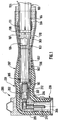
- Figures 1 and 2 show a plug 200 disposed at one end of a cable 100.
- the cable end has been stripped in a manner known per se.
- FIG. 1 shows a plug 200 disposed at one end of a cable 100.
- the cable end has been stripped in a manner known per se.
- FIG. 1 shows a conductive core 101, an insulating layer 102, a conductive screen 103 and an insulating outer sheath 104.
- a conductive plate 105 is interposed between the conductive screen 103 and the outer sheath 104. It is held by collars 107.108 enclosing the outer sheath 104.
- a grounding braid 106 is connected to the conductive plate 105.
- a ring of sealant 111 covers one end of the sheath outdoor 104.
- the socket 200 comprises in a manner known per se a multilayer sleeve 201 whose longitudinal section has, in this example, an L-shaped square, this sleeve having an axis 202 and comprising, as observed radially, an inner conductive layer 203, an insulating intermediate layer 204 and an outer conductive layer 205.
- the inner and outer layers could, as a variant, have other electrical characteristics capable of guiding an electric field, such as a semiconductor characteristic.
- the insulating layer 204 is flush with an interior surface 206 of the sleeve.
- the outer conductive layer 205 is flush with the inner surface 206 at the end of the sleeve receiving the cable, which for this purpose has a conical shape.
- the outer layer On the side of the end of the sleeve 201 receiving the cable 100, the outer layer has a cylindrical extension 210, which extends along the axis 201 of the sleeve over a length equal, in this example, to approximately half that of the sleeve 201.
- the sleeve 201 is made of an elastomeric material having a degree of elasticity allowing, after expansion and retraction of the sleeve, its adaptation to cables of substantially different diameters, more precisely cables whose diameter varies from simple to double.
- a particularly suitable elastomer is EPDM.
- the conical end 207 of the sleeve and its cylindrical extension 210 have, at rest, and at any point along the axis 202 of the sleeve, an inside diameter slightly less than the outside diameter which the end of the cable has at this point. with the smallest diameter, chosen from a series of cables of different dimensions, which we want to be able to adapt to the 200 socket. inside diameter of the conical end 207 and of the cylindrical extension 210 will also be chosen so that these parts exert, after their expansion then their retraction, a clamping force on said cable of smaller diameter.
- a socket 212 is crimped onto the conductive core 101 of the cable 100, a male contact pad 211 being fixed by screwing to a free end of the socket 212.
- the conical end 207 of the sleeve 201 and its cylindrical extension 210 are expanded radially to an inside diameter greater than the outside diameter of a corresponding part of the cable to be covered.
- the conical end 207 of the sleeve 201 and its cylindrical extension 210 have been expanded in the factory by means known in themselves, for example by using a vacuum chamber or a mandrel, and a tube 300 was introduced inside them to keep them expanding.
- the tube 300 consists of a tearable tape and comprises a cylindrical portion of small diameter 302, extended by a conical portion 303 widening towards a cylindrical portion of large diameter 304, the first cited portion covering a region of the cable in which appears its insulating layer 102, and the two other cited portions covering the cable earthing means and the putty 111.
- a ring 305 is arranged at a free end of the cylindrical portion of small diameter 302 of the tube 300 to facilitate the subsequent withdrawal of the latter.
- the conical end 207 of the sleeve 201 of the socket is supported on the small diameter cylindrical portion 302 of the tube 300 while its cylindrical extension 210 is supported on the conical portion 303 and the portion cylindrical large diameter 304.
- the cable end is prepared so as to be stripped and equipped on the one hand with its socket 212, on the other hand with its earthing means 105 to 108, 111 then it is inserted inside the socket 200.
- the male contact pad 211 is then aimed at the free end of the socket 212.
- the tube 300 is gradually withdrawn by an operator, from its end arranged on more inside the socket, by tearing the ribbon.
- the conical end 207 and the cylindrical extension 210 of the sleeve 201 then retract by elasticity on the corresponding parts of the cable 100. The situation obtained is illustrated in FIG. 2.
- cylindrical extension 210 covers the means for earthing the cable in the manner of a conventional earth cover, constituted by a tubular sheath with dimensional recovery, independent of the socket.
- the socket 200 does not have a cylindrical extension 210, the latter being replaced by a conventional earth cover disposed on the cable before retraction of the socket.
- the conical end 207 of the sleeve covers the earth cover over a short length.
- the conical end 207 of the sleeve 201 and its cylindrical extension 210 carry, on an external surface, traction lugs allowing their radial expansion by means of a device ensuring traction on these traction lugs, radially outwards from the catch.
- the conductive outer layer 205 and its cylindrical extension 210 have a heat-shrinkable characteristic while the rest of the sleeve has a non-heat-shrinkable characteristic.
- the mounting of such a socket on the cable 100 comprises a first phase in which the conical end 207 of the sleeve 201 and its cylindrical extension 210 are heated and then expanded radially in the factory by means known in themselves, for example by use vacuum chamber or mandrel, then they are cooled and keep expanding.
- the conical end 207 of the sleeve 201 and its cylindrical extension 210 are heated, so that they retract on the cable 100.
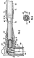
- junction body 400 intended to connect the ends of two cables 501, 502, these being of identical design to that 100 of FIGS. 1 and 2.
- the junction body 400 consists of a multilayer sleeve comprising, as observed radially, an inner conductive layer 401, an insulating intermediate layer 402 and an outer conductive layer 403. Similarly to the multilayer sleeve 201 of FIGS. 1 and 2 , the insulating intermediate layer 402 is flush with an inner surface of the junction body, and the conductive outer layer has a cylindrical extension 404 at two ends, which extends over approximately 40% of the length of the junction body.
- the junction body has two conical ends 405, 406 ( Figure 5).
- the conical ends 405, 406 and the cylindrical extensions 404 of the junction body are in a state of radial expansion, while a central region of the junction body lying between the two conical ends is not not expanded.
- the junction body 400 is maintained in mechanical expansion, by means of two tubes 601, 602 constituted by a tearable tape.
- Each tube comprises a portion in truncated cone 603 extended, on one side of larger diameter, by a cylindrical portion 604, the frusto-conical portion 603 supporting a conical end 406 of the junction body 400 and the cylindrical portion 604 supporting the cylindrical extension 404 thereof.
- a cylindrical sheath 408 has a longitudinal slot 409 and, at two ends, two flanges 410 projecting radially inwards. It comprises, on an outer surface and in an axially median region, an annular bead 411 in which an annular groove 412 is formed.
- This sheath is conductive and is made of an elastic material such as EPDM.
- the sheath 408 is arranged to intimately cover a crimped socket 413 joining the two cables 501, 502, the two flanges 410 of the sheath facing two ends of the crimped socket. It extends axially from an insulating layer 503 of a cable to an insulating layer 504 of the second cable.
- the inner layer 401 of the junction body 400 carries, on an inner face and in an axially median region, an annular bead 414 whose dimensions are adapted so that it is received in the annular groove 412 of the sleeve 408.
- the sleeve 408 has several functions. On the one hand, it adapts the internal diameter of the junction body 400 to the external diameter of the crimped socket 413. On the other hand, being in contact with these two parts, it connects them electrically and allows the evacuation of heat, from the crimped socket 413 up to the junction body 400.
- junction body 400 comprises a portion having a heat-shrinkable characteristic and is therefore maintained in the expanded state without having to use support tubes.
- the unexpanded central region of the junction body of FIGS. 3 and 4 has an internal diameter greater than the largest diameter of the bulkiest cable which it is desired to be able to adapt to this junction body, so that the latter can, in all cases, be threaded onto one of the cables 501, 502 before the assembly thereof.
- the assembly between the cores of these is carried out by means of the crimped socket 413.
- the sleeve 408 is attached to the crimped socket 413 after having been enlarged, taking advantage of its elasticity.
- the junction body is brought back on the sleeve 408 and its retraction is caused.
- FIG. 5 This situation is illustrated in which the conical ends 405, 406 of the junction body are supported on the insulating layer 503, 504 of the cables, and its cylindrical extensions 404 are supported on conductive screens and insulating outer sheaths Cables.
- cylindrical extension of the conductive outer layer of the plug or of the junction body to extend over a length greater than 20% of that of these.
Landscapes
- Cable Accessories (AREA)
- Connector Housings Or Holding Contact Members (AREA)
- Multi-Conductor Connections (AREA)
Description
L'invention concerne un dispositif de raccordement pour équiper une extrémité d'un câble électrique ou relier entre elles deux extrémités de deux câbles électriques, ce dispositif comprenant un manchon multicouche monobloc ayant un axe et présentant une couche intermédiaire isolante interposée entre deux couches radialement intérieure et extérieure aptes à assurer un guidage d'un champ électrique, ce manchon comportant une portion axialement médiane logeant des moyens de contact électrique destinés à coopérer avec une âme du ou des câbles, une première extrémité destinée à coopérer avec une extrémité isolée de câble et une seconde extrémité destinée à coopérer, soit avec un autre dispositif de raccordement, soit avec une autre extrémité isolée de câble.The invention relates to a connection device for equipping one end of an electrical cable or connecting two ends of two electrical cables together, this device comprising a monobloc multilayer sleeve having an axis and having an insulating intermediate layer interposed between two radially inner layers and external capable of guiding an electric field, this sleeve comprising an axially median portion housing electrical contact means intended to cooperate with a core of the cable or cables, a first end intended to cooperate with an isolated end of cable and a second end intended to cooperate, either with another connection device, or with another insulated cable end.
Elle concerne plus particulièrement les câbles de moyenne tension, c'est-à-dire dont la tension nominale est comprise entre 1 et 36 KV.It relates more particularly to medium voltage cables, that is to say those whose nominal voltage is between 1 and 36 KV.
Un problème particulier qui se pose pour équiper une extrémité de câble électrique d'un dispositif de raccordement est qu'il faut adapter le diamètre intérieur du manchon au diamètre du câble considéré. Cette adaptation nécessite d'avoir à disposition, soit plusieurs dispositifs de raccordement de taille différente, chacun étant conçu pour s'adapter exactement au diamètre du câble considéré, soit plusieurs tubes adaptateurs d'épaisseur différente, chaque tube permettant une adaptation du dispositif de raccordement à un câble de diamètre déterminé.A particular problem which arises in equipping an end of an electric cable with a connection device is that it is necessary to adapt the internal diameter of the sleeve to the diameter of the cable in question. This adaptation requires having available either several connection devices of different size, each designed to adapt exactly to the diameter of the cable considered, or several adapter tubes of different thickness, each tube allowing adaptation of the connection device. to a cable of determined diameter.
Ces solutions sont coûteuses car elles obligent à posséder un grand nombre de dispositifs de raccordement ou de tubes adaptateurs pour s'adapter à toute une gamme de câbles.These solutions are costly because they require a large number of connection devices or adapter tubes to adapt to a whole range of cables.
Une autre solution connue consiste à concevoir un manchon cylindrique droit pouvant être expansé dans son ensemble sur une plage de diamètres suffisamment grande pour pouvoir recevoir des câbles de diamètres différents, comme cela est enseigné dans les documents FR-A-2 592 825, EP-A-0.415.082 et GB-A-2.046.032.Another known solution consists in designing a straight cylindrical sleeve which can be expanded as a whole over a range of diameters large enough to be able to receive cables of different diameters, as taught in documents FR-A-2,592,825, EP- A-0.415.082 and GB-A-2.046.032.
Cette solution donne satisfaction. Toutefois, on constate que la mise en expansion puis ensuite la rétraction de l'ensemble du manchon prend un temps assez long. Par ailleurs, le maintien du manchon, pendant l'expansion, n'est pas aisé du fait que ce maintien ne doit pas s'opposer à l'effet d'expansion.This solution is satisfactory. However, we notes that the expansion and then the retraction of the entire sleeve takes a fairly long time. Furthermore, the maintenance of the sleeve, during expansion, is not easy since this maintenance must not oppose the expansion effect.
Enfin, certains dispositifs de raccordement ne peuvent subir une expansion dans leur ensemble, compte tenu de leur forme particulière ou du fait qu'ils comportent une partie interne massive, non expansible. Il s'agit notamment des prises de raccordement embrochables. Ces dispositifs ne peuvent donc être adaptés à différents diamètres de câbles que grâce à l'emploi des tubes adaptateurs précités.Finally, certain connection devices cannot undergo an expansion as a whole, taking into account their particular shape or the fact that they comprise a massive internal part, not expandable. These include plug-in connection sockets. These devices can therefore only be adapted to different cable diameters by using the aforementioned adapter tubes.
Le problème que vise à résoudre l'invention est de proposer des moyens permettant d'adapter toute sorte de dispositifs de raccordement à différents diamètres de câbles, d'une manière simple et sans utiliser des tubes adaptateurs connus.The problem which the invention aims to solve is to propose means making it possible to adapt all kinds of connection devices to different cable diameters, in a simple manner and without using known adapter tubes.
L'invention concerne à cet effet un dispositif de raccordement du genre cité au début de l'exposé, caractérisé en ce que la ou lesdites extrémités du manchon destinées à coopérer avec une extrémité de câble sont dans un état d'expansion radiale tel qu'elles présentent, en tout point le long de l'axe du manchon, un diamètre intérieur qui est supérieur au diamètre extérieur que présente l'extrémité de câble correspondante en ce point et qui sera inférieur à ce diamètre extérieur une fois qu'une rétraction desdites extrémités du manchon aura été provoquée, tandis que ladite portion axialement médiane du manchon et, le cas échéant, l'extrémité du manchon destinée à coopérer avec un autre dispositif de raccordement sont dans un état de non-expansion radiale.To this end, the invention relates to a connection device of the kind mentioned at the beginning of the description, characterized in that the one or more ends of the sleeve intended to cooperate with one end of the cable are in a state of radial expansion such that they have, at any point along the axis of the sleeve, an inside diameter which is greater than the outside diameter which the corresponding cable end has at this point and which will be less than this outside diameter once a retraction of said said ends of the sleeve will have been caused, while said axially middle portion of the sleeve and, where appropriate, the end of the sleeve intended to cooperate with another connection device are in a state of radial non-expansion.
Ainsi, les opérations d'expansion préalable du manchon puis de rétraction sur les câbles sont plus rapides puisqu'elles ne concernent qu'une partie du manchon.Thus, the operations of prior expansion of the sleeve and then of retraction on the cables are faster since they concern only part of the sleeve.
De plus, le manchon pourra, à tout moment, être saisi par ses portions non expansées en vue de son maintien.In addition, the sleeve may, at any time, be gripped by its unexpanded portions in order to maintain it.
Un tel dispositif peut être du genre possédant une extrémité non expansible, non destinée à s'appliquer autour d'une extrémité de câble : dans ce cas, seule l'extrémité destinée à coopérer avec le câble subira les opérations d'expansion puis de rétraction.Such a device can be of the type having a non-expandable end, not intended to be applied around a cable end: in this case, only the end intended to cooperate with the cable will undergo the operations of expansion then retraction.
Le dispositif précité est tel qu'il a subi préalablement une expansion et peut alors être déposé directement sur chantier par un opérateur.The aforementioned device is such that it has previously undergone an expansion and can then be deposited directly on site by an operator.
L'invention concerne aussi un tel dispositif, tel qu'il se présente avant expansion et qui incorpore en outre en lui-même des moyens de maintien en position expansée, c'est-à-dire un dispositif caractérisé en ce que la ou lesdites extrémités du manchon destinées à coopérer avec une extrémité de câble comportent des moyens de maintien susceptibles de les maintenir dans un état d'expansion radiale, tandis que ladite portion axialement médiane du manchon et, le cas échéant, l'extrémité du manchon destinée àcoopérer avec un autre dispositif de raccordement seront dans un état de non-expansion radiale.The invention also relates to such a device, as it appears before expansion and which also incorporates in itself means for holding in the expanded position, that is to say a device characterized in that the said one or more ends of the sleeve intended to cooperate with one end of the cable comprise holding means capable of keeping them in a state of radial expansion, while said axially median portion of the sleeve and, where appropriate, the end of the sleeve intended to cooperate with another connection device will be in a state of radial non-expansion.
Selon une première forme de réalisation, lesdits moyens de maintien consistent en ce que la ou les extrémités expansibles du manchon comprennent une portion en un matériau thermorétractable tandis que le reste du manchon est en un matériau non-thermorétractable.According to a first embodiment, said holding means consist in that the expandable end or ends of the sleeve comprise a portion made of a heat-shrinkable material while the rest of the sleeve is made of a non-heat-shrinkable material.
Selon une seconde forme de réalisation, lesdits moyens de maintien comprennent des pattes de traction solidaires d'une surface extérieure de chacune des extrémités expansibles du manchon.According to a second embodiment, said holding means comprise traction tabs integral with an outer surface of each of the expandable ends of the sleeve.
L'invention concerne encore un procédé pour monter un tel dispositif de raccordement à l'extrémité d'un câble électrique, caractérisé par les étapes consistant à expanser radialement seulement ladite ou lesdites extrémités expansibles du manchon dans une mesure telle qu'elles présentent, en tout point le long de l'axe du manchon, un diamètre intérieur qui est supérieur au diamètre extérieur que présente l'extrémité de câble correspondante en ce point, tout en maintenant ladite portion axialement médiane du manchon et, le cas échéant, l'extrémité du manchon destinée à coopérer avec un autre dispositif de raccordement dans un état de non-expansion radiale ; enfiler la ou les extrémités de câble à l'intérieur du dispositif de raccordement ainsi expansé et relier électriquement l'âme du ou des câbles auxdits moyens de contact électrique ; et provoquer la rétraction de ladite ou desdites extrémités expansées du manchon sur la ou les extrémités de câble.The invention also relates to a method for mounting such a connection device at the end of an electric cable, characterized by the steps consisting in radially expanding only said one or more expandable ends of the sleeve to an extent such that they present, in any point along the axis of the sleeve, an inside diameter which is greater than the outside diameter of the corresponding cable end at this point, while maintaining said axially median portion of the sleeve and, where appropriate, the end sleeve intended to cooperate with another connection device in a state of radial non-expansion; thread the cable end (s) inside the connection device thus expanded and electrically connect the core of the cable (s) to said electrical contact means; and causing said expanded end (s) of the sleeve to retract onto the cable end (s).
D'autres détails et avantages de l'invention apparaitront au cours de la description suivante d'une forme de réalisation préférée mais non limitative, en regard des dessins annexés sur lesquels :
- La figure 1 est une vue en coupe longitudinale d'une prise selon l'invention, avant sa reprise dimensionnelle sur un câble ;
- La figure 2 est une vue similaire, après la reprise dimensionnelle de la prise sur le câble.
- La figure 3 est une vue en coupe longitudinale d'un corps de jonction selon l'invention, avant sa reprise dimensionnelle sur une jonction entre câbles ;
- la figure 4 est une variante de la figure 3 ;
- la figure 5 est une vue du corps de jonction des figures 3 ou 4, après sa reprise dimensionnelle sur les câbles ; et
- la figure 6 est une vue en coupe selon la ligne VI-VI de la figure 3.
- Figure 1 is a longitudinal sectional view of a socket according to the invention, before its dimensional recovery on a cable;
- Figure 2 is a similar view, after the dimensional recovery of the plug on the cable.
- Figure 3 is a longitudinal sectional view of a junction body according to the invention, before its dimensional recovery on a junction between cables;
- Figure 4 is a variant of Figure 3;
- Figure 5 is a view of the junction body of Figures 3 or 4, after its dimensional recovery on the cables; and
- Figure 6 is a sectional view along line VI-VI of Figure 3.
Les figures 1 et 2 montrent une prise 200 disposée à une extrémité d'un câble 100. L'extrémité de câble a été dénudée de façon connue en soi. Sur les figures apparaissent, radialement de l'intérieur vers l'extérieur, une âme conductrice 101, une couche isolante 102, un écran conducteur 103 et une gaine extérieure isolante 104. Une plaquette conductrice 105 est interposée entre l'écran conducteur 103 et la gaine extérieure 104. Elle est maintenue par des colliers 107,108 enserrant la gaine extérieure 104. Une tresse de mise à la terre 106 est reliée à la plaquette conductrice 105. Un anneau de mastic d'étanchéité 111 recouvre une extrémité de la gaine extérieure 104.Figures 1 and 2 show a
La prise 200 comprend de façon connue en soi un manchon multicouche 201 dont la section longitudinale a, dans cet exemple, une forme d'équerre en L, ce manchon ayant un axe 202 et comportant, tel qu'observé radialement, une couche intérieure conductrice 203, une couche intermédiaire isolante 204 et une couche extérieure conductrice 205. Les couches intérieure et extérieure pourraient présenter, en variante, d'autres caractéristiques électriques aptes à assurer un guidage d'un champ électrique, telles qu'une caractéristique semi-conductrice.The
Au voisinage d'une extrémité 207 du manchon recevant le câble 100, et d'une autre extrémité embrochable 208, la couche isolante 204 affleure une surface intérieure 206 du manchon. De même, la couche extérieure conductrice 205 affleure la surface intérieure 206 à l'extrémité du manchon recevant le câble, laquelle présente à cet effet une forme conique.In the vicinity of one
Du côté de l'extrémité du manchon 201 recevant le câble 100, la couche extérieure présente un prolongement cylindrique 210, qui s'étend selon l'axe 201 du manchon sur une longueur égale, dans cet exemple, à environ la moitié de celle du manchon 201.On the side of the end of the
Le manchon 201 est réalisé en un matériau élastomère présentant un degré d'élasticité permettant, après expansion puis rétraction du manchon, son adaptation à des câbles de diamètres sensiblement différents, plus précisément des câbles dont le diamètre varie du simple au double. Un élastomère qui convient particulièrement est l'EPDM.The
L'extrémité conique 207 du manchon et son prolongement cylindrique 210 présentent, au repos, et en tout point le long de l'axe 202 du manchon, un diamètre intérieur un peu inférieur au diamètre extérieur que présente en ce point l'extrémité du câble de diamètre le plus petit, choisi parmi une série de câbles de différentes dimensions, que l'on veut pouvoir adapter à la prise 200. Le diamètre intérieur de l'extrémité conique 207 et du prolongement cylindrique 210 sera choisi en outre de façon que ces parties exercent, après leur expansion puis leur rétraction, une force de serrage sur ledit câble de plus petit diamètre.The
De façon connue en soi, une douille 212 est sertie sur l'âme conductrice 101 du câble 100, un plot de contact mâle 211 étant fixé par vissage à une extrémité libre de la douille 212.In a manner known per se, a
Le montage de la prise 200 sur le câble 100 va maintenant être décrit. Dans une première phase, l'extrémité conique 207 du manchon 201 et son prolongement cylindrique 210 sont expansés radialement jusqu'à un diamètre intérieur supérieur au diamètre extérieur d'une partie correspondante du câble à recouvrir.The mounting of the
Dans cet exemple, l'extrémité conique 207 du manchon 201 et son prolongement cylindrique 210 ont été expansés en usine par des moyens connus en eux-mêmes, par exemple par utilisation d'une chambre à vide ou d'un mandrin, et un tube 300 a été introduit à l'intérieur de ceux-ci pour les maintenir en expansion.In this example, the
Le tube 300 est constitué d'un ruban déchirable et comprend une portion cylindrique de petit diamètre 302, prolongée par une portion conique 303 s'élargissant vers une portion cylindrique de grand diamètre 304, la première portion citée recouvrant une région du câble dans laquelle apparaît sa couche isolante 102, et les deux autres portions citées recouvrant les moyens de mise à la terre du câble et le mastic 111.The
De façon connue en soi, une bague 305 est disposée à une extrémité libre de la portion cylindrique de petit diamètre 302 du tube 300 pour faciliter le retrait ultérieur de celui-ci.In a manner known per se, a
L'extrémité conique 207 du manchon 201 de la prise s'appuie sur la portion cylindrique de petit diamètre 302 du tube 300 tandis que son prolongement cylindrique 210 s'appuie sur la portion conique 303 et la portion cylindrique de grand diamètre 304.The
Dans une seconde phase de montage sur site, l'extrémité de câble est préparée de façon à être dénudée et équipée d'une part de sa douille 212, d'autre part de ses moyens de mise à la terre 105 à 108, 111 puis elle est insérée à l'intérieur de la prise 200. Le plot de contact mâle 211 est alors visé sur l'extrémité libre de la douille 212. Ensuite, le tube 300 est retiré progressivement par un opérateur, à partir de son extrémité disposée le plus à l'intérieur de la prise, par déchirement du ruban. L'extrémité conique 207 et le prolongement cylindrique 210 du manchon 201 se rétractent alors par élasticité sur les parties correspondantes du câble 100. La situation obtenue est illustrée sur la figure 2.In a second phase of assembly on site, the cable end is prepared so as to be stripped and equipped on the one hand with its
On notera que le prolongement cylindrique 210 recouvre les moyens de mise à la terre du câble à la manière d'un capot de terre classique, constitué par une gaine tubulaire à reprise dimensionnelle, indépendante de la prise.It will be noted that the
Selon une variante moins avantageuse non représentée sur les figures, la prise 200 ne comporte pas de prolongement cylindrique 210, celui-ci étant remplacé par un capot de terre classique disposé sur le câble avant rétraction de la prise. Dans ce cas, l'extrémité conique 207 du manchon recouvre le capot de terre sur une faible longueur.According to a less advantageous variant not shown in the figures, the
En variante, l'extrémité conique 207 du manchon 201 et son prolongement cylindrique 210 portent, sur une surface extérieure, des pattes de traction permettant leur expansion radiale grâce à un dispositif assurant une traction sur ces pattes de traction, radialement vers l'extérieur de la prise.As a variant, the
En variante, à l'extrémité conique 207 du manchon 201, la couche extérieure conductrice 205 et son prolongement cylindrique 210 présentent une caractéristique thermorétractable alors que le reste du manchon présente une caractéristique non thermorétractable.Alternatively, at the
Le montage d'une telle prise sur le câble 100 comprend une première phase dans laquelle l'extrémité conique 207 du manchon 201 et son prolongement cylindrique 210 sont chauffés puis expansés radialement en usine par des moyens connus en eux-mêmes, par exemple par utilisation d'une chambre à vide ou d'un mandrin, puis ils sont refroidis et se maintiennent alors en expansion.The mounting of such a socket on the
Dans une seconde phase de montage sur site, l'extrémité conique 207 du manchon 201 et son prolongement cylindrique 210 sont réchauffés, de sorte qu'ils se rétractent sur le câble 100.In a second phase of on-site assembly, the
L'invention s'applique de façon tout à fait similaire à un corps de jonction 400 destiné à relier des extrémités de deux câbles 501, 502, ceux-ci étant de conception identique à celui 100 des figures 1 et 2.The invention applies quite similarly to a
Le corps de jonction 400 est constitué d'un manchon multicouche comportant, tel qu'observé radialement, une couche intérieure conductrice 401, une couche intermédiaire isolante 402 et une couche extérieure conductrice 403. De façon semblable au manchon multicouche 201 des figures 1 et 2, la couche intermédiaire isolante 402 affleure une surface intérieure du corps de jonction, et la couche extérieure conductrice présente un prolongement cylindrique 404 à deux extrémités, qui s'étend sur environ 40 % de la longueur du corps de jonction. Le corps de jonction présente deux extrémités coniques 405, 406 (figure 5).The
Sur les figures 3 et 4, les extrémités coniques 405, 406 et les prolongements cylindriques 404 du corps de jonction sont dans un état d'expansion radiale, tandis qu'une région centrale du corps de jonction comprise entre les deux extrémités coniques n'est pas expansée.In FIGS. 3 and 4, the conical ends 405, 406 and the
Dans l'exemple de la figure 3, le corps de jonction 400 est maintenu en expansion mécaniquement, au moyen de deux tubes 601, 602 constitués d'un ruban déchirable. Chaque tube comprend une portion en tronc de cône 603 prolongée, d'un côté de plus grand diamètre, par une portion cylindrique 604, la portion en tronc de cône 603 supportant une extrémité conique 406 du corps de jonction 400 et la portion cylindrique 604 supportant le prolongement cylindrique 404 de celui-ci.In the example of FIG. 3, the
Un fourreau 408 cylindrique présente une fente longitudinale 409 et, à deux extrémités, deux rebords 410 saillant radialement vers l'intérieur. Il comporte, sur une surface extérieure et dans une région axialement médiane, un bourrelet annulaire 411 dans lequel est ménagée une rainure annulaire 412. Ce fourreau est conducteur et est réalisé en un matériau élastique tel qu'en EPDM.A
Le fourreau 408 est agencé pour recouvrir intimement une douille sertie 413 réunissant les deux câbles 501, 502, les deux rebords 410 du fourreau faisant face à deux extrémités de la douille sertie. Il s'étend axialement depuis une couche isolante 503 d'un câble jusqu'à une couche isolante 504 du second câble.The
La couche intérieure 401 du corps de jonction 400 porte, sur une face intérieure et dans une région axialement médiane, un bourrelet annulaire 414 dont les dimensions sont adaptées pour qu'il soit reçu dans la rainure annulaire 412 du fourreau 408.The
Le fourreau 408 a plusieurs fonctions. D'une part, il adapte le diamètre intérieur du corps de jonction 400 au diamètre extérieur de la douille sertie 413. D'autre part, étant en contact avec ces deux pièces, il les relie électriquement et permet l'évacuation de chaleur, depuis la douille sertie 413 jusqu'au corps de jonction 400.The
L'exemple de la figure 4 se distingue de celui de la figure 3 en ce que le corps de jonction 400 comprend une portion présentant une caractéristique thermorétractable et est donc maintenu dans l'état expansé sans avoir à utiliser des tubes de soutien.The example of Figure 4 differs from that of Figure 3 in that the
La région centrale non expansée du corps de jonction des figures 3 et 4 présente un diamètre intérieur supérieur au plus grand diamètre du câble le plus volumineux que l'on souhaite pouvoir adapter à ce corps de jonction, de façon que ce dernier puisse, dans tous les cas, être enfilé sur l'un des câbles 501, 502 avant l'assemblage de ceux-ci.The unexpanded central region of the junction body of FIGS. 3 and 4 has an internal diameter greater than the largest diameter of the bulkiest cable which it is desired to be able to adapt to this junction body, so that the latter can, in all cases, be threaded onto one of the
Sur site, le corps de jonction étant enfilé sur l'un des câbles, l'assemblage entre les âmes de ceux-ci est réalisé au moyen de la douille sertie 413. Puis, le fourreau 408 est rapporté sur la douille sertie 413 après avoir été élargi, mettant à profit son élasticité. Ensuite, le corps de jonction est ramené sur le fourreau 408 et sa rétraction est provoquée. Cette situation est illustrée sur la figure 5 dans laquelle les extrémités coniques 405, 406 du corps de jonction s'appuient sur la couche isolante 503, 504 des câbles, et ses prolongements cylindriques 404 s'appuient sur des écrans conducteurs et des gaines extérieures isolantes des câbles.On site, the junction body being threaded on one of the cables, the assembly between the cores of these is carried out by means of the crimped
Dans tous les cas, il sera avantageux que le prolongement cylindrique de la couche extérieure conductrice de la prise ou de corps de jonction s'étende sur une longueur supérieure à 20 % de celle de ceux-ci.In all cases, it will be advantageous for the cylindrical extension of the conductive outer layer of the plug or of the junction body to extend over a length greater than 20% of that of these.
Claims (12)
- A connection device (200) for equipping one end of a power cable (100) or for joining together two ends of two power cables, this device comprising a one-piece multilayer sleeve having an axis (202) and having an insulating intermediate layer (204) interposed between two layers, a radially inner layer (203) and a radially outer layer (205), which are capable of guiding an electric field, this sleeve including an axially central portion housing electrical contacting means (211, 212) intended to interact with a core of the cable or cables, a first end (207; 405) intended to interact with an insulated cable end and a second end (406) intended to interact either with another connection device or with another insulated cable end, characterized in that the said end or ends (207; 405, 406) of the sleeve which are intended to interact with a cable end are in a state of radial expansion such that, at every point along the axis (202) of the sleeve, they have an internal diameter which is greater than the external diameter of the corresponding cable end at this point and which will be less than this external diameter once the said ends of the sleeve have been made to shrink, whereas the said axially central portion of the sleeve and, as the case may be, that end (208) of the sleeve intended to interact with another connection device are not in a radially expanded state.
- A device according to claim 1, in which the expanded end or ends (207; 405, 406) of the sleeve comprise a portion made of heat-shrinkable material whereas the rest of the sleeve is made of a material which is not heat-shrinkable.
- A device according to claim 1, in which the expanded end or ends (207; 405, 406) of the sleeve are made of an elastic material.
- A device according to claim 3, in which the expanded end or ends (207; 405, 406) of the sleeve carry tensioning fingers on an external surface and the connection device comprises expansion means interacting with the said tensioning fingers in order to apply an outwardly directed radial tensile force on them.
- A device according to claim 3, which comprises, inside each of the expanded ends of the sleeve, a tube (300) consisting of a pull-out tape on which the said expanded end bears.
- A connection device (200) for equipping one end of a power cable (100) or for joining together two ends of two power cables, this device comprising a one-piece multilayer sleeve having an axis (202) and having an insulating intermediate layer (204) interposed between two layers, a radially inner layer (203) and a radially outer layer (205), which are capable of guiding an electric field, this sleeve including an axially central portion housing electrical contacting means (211, 212) intended to interact with a core of the cable or cables, a first end (207; 405) intended to interact with an insulated cable end and a second end (406) intended to interact either with another connection device or with another insulated cable end, characterized in that the said end or ends (207; 405, 406) of the sleeve which are intended to interact with a cable end include holding means capable of holding them in place in a state of radial expansion, whereas the said axially central portion of the sleeve and, as the case may be, that end (208) of the sleeve intended to interact with another connection device will not be in a radially expanded state.
- A device according to claim 6, in which the said holding means consist in that the expansible ends (207; 405, 406) of the sleeve comprise a portion made of a heat-shrinkable material whereas the rest of the sleeve is made of a material which is not heat-shrinkable.
- A device according to claim 6, in which the said holding means comprise tensioning fingers fastened to an external surface of each of the expansible ends (207; 405, 406) of the sleeve.
- A device according to any one of claims 6 to 8, in which, at the end (207) or at the ends (405, 406) of the sleeve interacting with a cable end, the external layer (205) extends axially beyond the insulating layer (204) as a cylindrical extension (210) to such an extent that the said extension can cover a stripped portion of a conductive screen (103) and an external sheath of the cable.
- A process for mounting a connection device (200) at the end of a power cable (100) or between two ends of two power cables (501, 502), each cable including a conductive core (101), an insulating layer (102) covering the core, a conductive screen (103) covering the insulating layer, and an external sheath (104) covering the conductive screen (103), the connection device comprising a one-piece multilayer sleeve having an axis (202) and having an insulating intermediate layer (204) interposed between two layers, a radially inner layer (203) and a radially outer layer (205), which are capable of guiding an electric field, this sleeve including an axially central portion housing electrical contacting means (211, 212) intended to interact with a core of the cable or cables, a first end (207; 405) intended to interact with an insulated cable end and a second end (406) intended to interact either with another connection device or with another insulated cable end, the end or ends (207; 405, 406) of the sleeve which are intended to interact with a cable end being capable of being brought into a state of radial expansion, whereas the said axially central portion of the sleeve and, as the case may be, that end (208) of the sleeve intended to interact with another connection device will not be in a state of radial expansion, characterized by the following steps:- of radially expanding just the said expansible end or ends (207; 405, 406) of the sleeve to such an extent that they have, at every point along the axis (202) of the sleeve, an internal diameter which is greater than the external diameter of the corresponding cable end at this point, while at the same time holding in place the said axially central portion of the sleeve and, as the case may be, that end (208) of the sleeve intended to interact with another connection device not in a state of radial expansion;- of slipping the cable end or ends into the connection device thus expanded and electrically connecting the core (101) of the cable or cables to the said electrical contacting means (211); and- of causing the said expanded end or ends (207; 405, 406) of the sleeve to shrink onto the cable end or ends.
- The process according to claim 10, in which the sleeve (201) is made of an elastic material and, after expanding the end or ends (207; 405, 406) of the sleeve which are intended to interact with the end or ends of the cable, a tube (300), which has an internal diameter greater than the external diameter of the corresponding cable end and is capable of holding in place the end or ends (207) of the sleeve in the expanded state, is inserted into each of the latter and, after slipping each cable end into the corresponding tube (300), the latter is removed.
- A process according to claim 10, in which the said end or ends (207; 405, 406) of the sleeve which are intended to interact with the end or ends of the cable comprise a portion made of a heat-shrinkable material, characterized by the following steps:- of heating the said end or ends (207) of the sleeve which are intended to interact with the cable end or ends;- of radially expanding this end or these ends (207) as far as an internal diameter greater than the external diameter of the corresponding cable end;- of cooling this end or these ends in order to hold them in place in the expanded state;- of slipping this cable end or these cable ends into the connection device thus expanded and electrically connecting the core (101) of the cable or cables to the said electrical contacting means (211); and- of heating the said expanded sleeve end or ends (207) in order to cause them to shrink onto the cable end or ends.
Applications Claiming Priority (2)
| Application Number | Priority Date | Filing Date | Title |
|---|---|---|---|
| FR9102949A FR2674073B1 (en) | 1991-03-12 | 1991-03-12 | CONNECTION DEVICE FOR ONE OR TWO ELECTRIC CABLES, AND PROCEDURE FOR MOUNTING THIS DEVICE AT THE END OF THE CABLE (S) |
| FR9102949 | 1991-03-12 |
Publications (3)
| Publication Number | Publication Date |
|---|---|
| EP0504035A2 EP0504035A2 (en) | 1992-09-16 |
| EP0504035A3 EP0504035A3 (en) | 1992-12-16 |
| EP0504035B1 true EP0504035B1 (en) | 1996-01-03 |
Family
ID=9410619
Family Applications (1)
| Application Number | Title | Priority Date | Filing Date |
|---|---|---|---|
| EP92400613A Expired - Lifetime EP0504035B1 (en) | 1991-03-12 | 1992-03-10 | Connecting device for one or two power cables, and process for mounting this device at the end of the cables |
Country Status (6)
| Country | Link |
|---|---|
| US (1) | US5230640A (en) |
| EP (1) | EP0504035B1 (en) |
| BR (1) | BR9200938A (en) |
| DE (1) | DE69207238T2 (en) |
| ES (1) | ES2084299T3 (en) |
| FR (1) | FR2674073B1 (en) |
Cited By (3)
| Publication number | Priority date | Publication date | Assignee | Title |
|---|---|---|---|---|
| US5856634A (en) * | 1997-03-19 | 1999-01-05 | Raychem Corporation | Recoverable article |
| US6329600B1 (en) | 1998-12-10 | 2001-12-11 | Nexans | Screen connection for mechanico retractable products |
| EP2819250A1 (en) | 2013-06-26 | 2014-12-31 | 3M Innovative Properties Company | Cable connection device |
Families Citing this family (64)
| Publication number | Priority date | Publication date | Assignee | Title |
|---|---|---|---|---|
| EP0689728B1 (en) * | 1993-03-16 | 1997-10-29 | Minnesota Mining And Manufacturing Company | A pre-stretched, elastomeric article |
| US6504103B1 (en) | 1993-03-19 | 2003-01-07 | Cooper Industries, Inc. | Visual latching indicator arrangement for an electrical bushing and terminator |
| US7642465B2 (en) * | 1994-06-20 | 2010-01-05 | Cooper Technologies Company | Visual latching indicator arrangement for an electrical bushing and terminator |
| US6984791B1 (en) | 1993-03-19 | 2006-01-10 | Cooper Technologies Company | Visual latching indicator arrangement for an electrical bushing and terminator |
| JP3278502B2 (en) * | 1993-08-13 | 2002-04-30 | 住友スリーエム株式会社 | Insulation tube for wire connection |
| US5651699A (en) * | 1994-03-21 | 1997-07-29 | Holliday; Randall A. | Modular connector assembly for coaxial cables |
| US5402566A (en) * | 1994-04-04 | 1995-04-04 | The Whitaker Corporation | Method and machine for attaching an electrical connector to a coaxial cable |
| ES2117302T3 (en) * | 1994-04-25 | 1998-08-01 | Minnesota Mining & Mfg | A PRESSURIZED ELASTOMERIC ITEM. |
| DE4424072C1 (en) * | 1994-07-08 | 1996-01-25 | Rheydt Kabelwerk Ag | Plug-in closure |
| DE19500804A1 (en) * | 1995-01-13 | 1996-07-18 | Minnesota Mining & Mfg | Elastic deformable, almost T-shaped sheath for an electrical cable termination connection |
| FR2741484B1 (en) * | 1995-11-21 | 1997-12-19 | Silec Liaisons Elec | ELECTRICAL CONNECTION PIECE |
| FR2756674B1 (en) * | 1996-12-02 | 1999-01-08 | Telecommunications Sa | PROTECTIVE SLEEVE FOR CABLE JUNCTION |
| US5957712A (en) * | 1997-07-30 | 1999-09-28 | Thomas & Betts International, Inc. | Loadbreak connector assembly which prevents switching flashover |
| US6939151B2 (en) * | 1997-07-30 | 2005-09-06 | Thomas & Betts International, Inc. | Loadbreak connector assembly which prevents switching flashover |
| US6168447B1 (en) | 1997-07-30 | 2001-01-02 | Thomas & Betts International, Inc. | Loadbreak connector assembly which prevents switching flashover |
| US7044760B2 (en) * | 1997-07-30 | 2006-05-16 | Thomas & Betts International, Inc. | Separable electrical connector assembly |
| DE19746313A1 (en) * | 1997-10-21 | 1999-04-22 | Abb Patent Gmbh | Cable termination or cable sleeve with geometric field control |
| DE19845776A1 (en) * | 1998-09-22 | 2000-03-23 | Siemens Ag | T-shaped connector for gas-insulated MV switchgear |
| JP3532534B2 (en) * | 2001-05-29 | 2004-05-31 | 矢崎総業株式会社 | Coaxial connector |
| US6905356B2 (en) * | 2002-05-16 | 2005-06-14 | Homac Mfg. Company | Electrical connector including thermoplastic elastomer material and associated methods |
| US6796820B2 (en) * | 2002-05-16 | 2004-09-28 | Homac Mfg. Company | Electrical connector including cold shrink core and thermoplastic elastomer material and associated methods |
| US7104823B2 (en) * | 2002-05-16 | 2006-09-12 | Homac Mfg. Company | Enhanced separable connector with thermoplastic member and related methods |
| US6790063B2 (en) | 2002-05-16 | 2004-09-14 | Homac Mfg. Company | Electrical connector including split shield monitor point and associated methods |
| US6830475B2 (en) * | 2002-05-16 | 2004-12-14 | Homac Mfg. Company | Electrical connector with visual seating indicator and associated methods |
| US6811418B2 (en) * | 2002-05-16 | 2004-11-02 | Homac Mfg. Company | Electrical connector with anti-flashover configuration and associated methods |
| US7104822B2 (en) * | 2002-05-16 | 2006-09-12 | Homac Mfg. Company | Electrical connector including silicone elastomeric material and associated methods |
| NL1023128C2 (en) * | 2003-04-09 | 2004-10-18 | Lovink Enertech B V | Cable sleeve. |
| US7530841B2 (en) * | 2003-09-15 | 2009-05-12 | Corning Cabelcon A/S | Coaxial angle connector |
| DE20316059U1 (en) * | 2003-10-20 | 2003-12-18 | Asm Automation Sensorik Messtechnik Gmbh | Grommet |
| US7182647B2 (en) * | 2004-11-24 | 2007-02-27 | Cooper Technologies Company | Visible break assembly including a window to view a power connection |
| US7572133B2 (en) | 2005-11-14 | 2009-08-11 | Cooper Technologies Company | Separable loadbreak connector and system |
| US7767909B2 (en) * | 2006-05-05 | 2010-08-03 | 3M Innovative Properties Company | Tubular terminal for a cable |
| EP1852949B1 (en) | 2006-05-05 | 2009-12-02 | 3M Innovative Properties Company | Tubular terminal for a cable |
| US7854620B2 (en) | 2007-02-20 | 2010-12-21 | Cooper Technologies Company | Shield housing for a separable connector |
| US7950939B2 (en) | 2007-02-22 | 2011-05-31 | Cooper Technologies Company | Medium voltage separable insulated energized break connector |
| US7666012B2 (en) | 2007-03-20 | 2010-02-23 | Cooper Technologies Company | Separable loadbreak connector for making or breaking an energized connection in a power distribution network |
| US7633741B2 (en) | 2007-04-23 | 2009-12-15 | Cooper Technologies Company | Switchgear bus support system and method |
| US7661979B2 (en) | 2007-06-01 | 2010-02-16 | Cooper Technologies Company | Jacket sleeve with grippable tabs for a cable connector |
| CN101340035B (en) * | 2007-07-02 | 2010-08-25 | 3M创新有限公司 | Adapter, cable connector having the adapter and cable connector component |
| CN101388536B (en) * | 2007-09-11 | 2013-05-29 | 3M创新有限公司 | Connector sleeve and cable connector component having the same |
| US7695291B2 (en) | 2007-10-31 | 2010-04-13 | Cooper Technologies Company | Fully insulated fuse test and ground device |
| US7950940B2 (en) | 2008-02-25 | 2011-05-31 | Cooper Technologies Company | Separable connector with reduced surface contact |
| US7670162B2 (en) | 2008-02-25 | 2010-03-02 | Cooper Technologies Company | Separable connector with interface undercut |
| US7905735B2 (en) | 2008-02-25 | 2011-03-15 | Cooper Technologies Company | Push-then-pull operation of a separable connector system |
| US8056226B2 (en) | 2008-02-25 | 2011-11-15 | Cooper Technologies Company | Method of manufacturing a dual interface separable insulated connector with overmolded faraday cage |
| US8109776B2 (en) | 2008-02-27 | 2012-02-07 | Cooper Technologies Company | Two-material separable insulated connector |
| US7811113B2 (en) | 2008-03-12 | 2010-10-12 | Cooper Technologies Company | Electrical connector with fault closure lockout |
| US7878849B2 (en) * | 2008-04-11 | 2011-02-01 | Cooper Technologies Company | Extender for a separable insulated connector |
| US7958631B2 (en) * | 2008-04-11 | 2011-06-14 | Cooper Technologies Company | Method of using an extender for a separable insulated connector |
| US7708576B2 (en) * | 2008-08-25 | 2010-05-04 | Cooper Industries, Ltd. | Electrical connector including a ring and a ground shield |
| US20100224407A1 (en) * | 2009-03-05 | 2010-09-09 | David Charles Hughes | Observation Port or Membrane to Assist the Proper Positioning of a Cable Accessory on a Cable |
| US20100223785A1 (en) * | 2009-03-05 | 2010-09-09 | Cooper Technologies Company | Method of Using an Observation Port or membrane to Assist the Proper Positioning of a Cable Accessory on a Cable |
| RU2490766C2 (en) * | 2009-05-01 | 2013-08-20 | 3М Инновейтив Пропертиз Компани | Cold shrinking connection device |
| US7901243B1 (en) | 2010-03-30 | 2011-03-08 | Tyco Electronics Corporation | Methods and systems for forming a protected disconnectable joint assembly |
| CN103283101A (en) * | 2010-12-22 | 2013-09-04 | 普睿司曼股份公司 | Jointing assembly for electrical cables |
| US9059581B2 (en) | 2011-04-28 | 2015-06-16 | Richards Manufacturing Company, A New Jersey Limited Partnership | Cold shrinkable primary joint |
| EP2710683B1 (en) * | 2011-05-20 | 2019-08-28 | 3M Innovative Properties Company | Dead front cable terminal with isolated shield |
| US9762046B2 (en) * | 2013-04-18 | 2017-09-12 | Richards Manufacturing Company Sales, Inc. | Sleeve for shielding electrical joint |
| US9444176B2 (en) * | 2013-06-28 | 2016-09-13 | Thomas & Betts International, Llc | Electrical connector having cold shrink component |
| MX368430B (en) * | 2013-12-20 | 2019-10-03 | Ppc Broadband Inc | Radio frequency sheilding for microcoaxial cable connectors. |
| DE102018116416A1 (en) * | 2018-07-06 | 2020-01-09 | Nkt Gmbh & Co. Kg | coupling sleeve |
| CN111478134B (en) * | 2020-03-13 | 2021-04-16 | 中国电子科技集团公司第二十九研究所 | Sealed waterproof type radio frequency cable subassembly tied in a bundle |
| US11631971B2 (en) * | 2020-10-19 | 2023-04-18 | CCG International Holdings Limited | Cable gland for armored electrical or fiber optic cables |
| CA3153815A1 (en) | 2021-03-24 | 2022-09-24 | Richards Mfg. Co., A New Jersey Limited Partnership | Cold shrink core |
Family Cites Families (13)
| Publication number | Priority date | Publication date | Assignee | Title |
|---|---|---|---|---|
| US3541495A (en) * | 1968-08-12 | 1970-11-17 | Raychem Corp | Connector for termination of coaxial cable |
| NL141718C (en) * | 1969-04-18 | Amp Inc | ||
| US3774141A (en) * | 1971-11-24 | 1973-11-20 | Vaco Products Co | Terminal connector and insulating sleeve therefor |
| US4196308A (en) * | 1976-01-28 | 1980-04-01 | Raychem Corporation | Insulated crimp splicer |
| US4304616A (en) * | 1979-04-02 | 1981-12-08 | Raychem Corporation | Radially shrinkable sleeves |
| DE8219184U1 (en) * | 1982-07-05 | 1982-10-14 | Walter Rose Gmbh & Co Kg, 5800 Hagen | Device for coupling two coaxial cable ends |
| GB8325402D0 (en) * | 1983-09-22 | 1983-10-26 | Raychem Gmbh | Electrical apparatus |
| US4714438A (en) * | 1985-07-19 | 1987-12-22 | Bicc Public Limited Company | Electric cable joints |
| FR2592825B1 (en) * | 1986-01-13 | 1988-03-11 | Artema | AUXILIARY POSITIONING SLEEVE, DEVICE HAVING SUCH A SLEEVE AND CORRESPONDING POSITIONING METHOD |
| DE3837120A1 (en) * | 1988-11-02 | 1990-05-03 | Rheydt Kabelwerk Ag | Cable connection |
| DE9002070U1 (en) * | 1989-02-24 | 1990-04-26 | Minnesota Mining & Mfg. Co., Saint Paul, Minn. | Adapter for an electrical cable termination |
| IT1230364B (en) * | 1989-08-01 | 1991-10-18 | Pirelli Cavi Spa | STORAGE ELEMENT FOR COATING OF ELECTRIC CABLE JOINTS, APPLICABLE TO SEVERAL CABLES OF DIFFERENT DIAMETER, WITH INSULATING LAYER THAT ALLOWS RESIDUAL DEFORMATION. |
| DE3943296C2 (en) * | 1989-12-29 | 1994-08-11 | Minnesota Mining & Mfg | Sleeve for covering a connection or an end of an electrical cable |
-
1991
- 1991-03-12 FR FR9102949A patent/FR2674073B1/en not_active Expired - Lifetime
-
1992
- 1992-03-09 US US07/848,015 patent/US5230640A/en not_active Expired - Lifetime
- 1992-03-10 EP EP92400613A patent/EP0504035B1/en not_active Expired - Lifetime
- 1992-03-10 DE DE69207238T patent/DE69207238T2/en not_active Expired - Lifetime
- 1992-03-10 ES ES92400613T patent/ES2084299T3/en not_active Expired - Lifetime
- 1992-03-12 BR BR929200938A patent/BR9200938A/en not_active IP Right Cessation
Cited By (3)
| Publication number | Priority date | Publication date | Assignee | Title |
|---|---|---|---|---|
| US5856634A (en) * | 1997-03-19 | 1999-01-05 | Raychem Corporation | Recoverable article |
| US6329600B1 (en) | 1998-12-10 | 2001-12-11 | Nexans | Screen connection for mechanico retractable products |
| EP2819250A1 (en) | 2013-06-26 | 2014-12-31 | 3M Innovative Properties Company | Cable connection device |
Also Published As
| Publication number | Publication date |
|---|---|
| BR9200938A (en) | 1992-11-17 |
| FR2674073A1 (en) | 1992-09-18 |
| FR2674073B1 (en) | 1996-05-10 |
| ES2084299T3 (en) | 1996-05-01 |
| DE69207238T2 (en) | 1996-07-18 |
| EP0504035A2 (en) | 1992-09-16 |
| US5230640A (en) | 1993-07-27 |
| EP0504035A3 (en) | 1992-12-16 |
| DE69207238D1 (en) | 1996-02-15 |
Similar Documents
| Publication | Publication Date | Title |
|---|---|---|
| EP0504035B1 (en) | Connecting device for one or two power cables, and process for mounting this device at the end of the cables | |
| EP0974179A1 (en) | Connecting cord junction | |
| FR2493050A1 (en) | CONNECTOR FOR COAXIAL CABLE | |
| CH626754A5 (en) | Method for joining high-voltage cables and device for implementing this method | |
| FR2503476A1 (en) | Fitting protective sheath over electric cable - using cylindrical mandrel to carry sheath which is rolled forward over bared cable end | |
| EP1394900B1 (en) | Connector for two electrical power cables and connection including this connector | |
| EP0933856B1 (en) | Cold shrinkable sealing sleeve for electrical cable | |
| EP0132208A1 (en) | Anchoring clamp for insulated supporting cables with several conductors | |
| EP0549942B1 (en) | Electrical cable junction, premounted junction assembly and manufacturing process | |
| EP0862801B1 (en) | Electrical coupling part | |
| FR2527015A1 (en) | Demountable cylindrical connector for single-core cable - has male and female sections which join in snap-action push-fit which can be disconnected without special tool | |
| EP0732768B1 (en) | Process for making an electrical connection to a metallic screen of a power cable and ring for carrying out the process | |
| EP0683556B1 (en) | Piece of electrical connection of a protective sleeve to an end of a semiconductive screen of an electrical cable | |
| CA2238260C (en) | Electrical coupling part | |
| FR2825529A1 (en) | EXPANSION HOLDING DEVICE OF AN ELASTIC SLEEVE | |
| EP0246974A1 (en) | Insulating sleeve for the one-pole end of an electrical conductor | |
| FR2709025A1 (en) | Spring-loaded (elastic) electrical contact | |
| EP0278844A1 (en) | Electrical cable, especially one insulated with impregnated paper, at the end of which a connecting device is provided | |
| CA1296400C (en) | Electrical cable with impregnated paper sheathing and end connector | |
| BE835135Q (en) | CONNECTION DEVICE FOR ELECTRICAL INSTALLATION | |
| EP2750255B1 (en) | Device for low voltage cables | |
| EP0508884A1 (en) | Optical fibre cable connector | |
| EP2272135B1 (en) | Device for preventing the establishment of an electric arc between two conductive elements | |
| FR3104838A1 (en) | Protection set for at least one cable | |
| FR2917245A1 (en) | Screened electric wire and connection wire connecting device for use at ground, has electricity conducting element with two parts having two set of housings respectively to receive screened wire and element, and connection wire at ground |
Legal Events
| Date | Code | Title | Description |
|---|---|---|---|
| PUAI | Public reference made under article 153(3) epc to a published international application that has entered the european phase |
Free format text: ORIGINAL CODE: 0009012 |
|
| AK | Designated contracting states |
Kind code of ref document: A2 Designated state(s): DE ES GB IT |
|
| PUAL | Search report despatched |
Free format text: ORIGINAL CODE: 0009013 |
|
| AK | Designated contracting states |
Kind code of ref document: A3 Designated state(s): DE ES GB IT |
|
| 17P | Request for examination filed |
Effective date: 19930308 |
|
| 17Q | First examination report despatched |
Effective date: 19950307 |
|
| RAP3 | Party data changed (applicant data changed or rights of an application transferred) |
Owner name: CABLES PIRELLI |
|
| GRAA | (expected) grant |
Free format text: ORIGINAL CODE: 0009210 |
|
| AK | Designated contracting states |
Kind code of ref document: B1 Designated state(s): DE ES GB IT |
|
| REF | Corresponds to: |
Ref document number: 69207238 Country of ref document: DE Date of ref document: 19960215 |
|
| ITF | It: translation for a ep patent filed | ||
| GBT | Gb: translation of ep patent filed (gb section 77(6)(a)/1977) |
Effective date: 19960227 |
|
| REG | Reference to a national code |
Ref country code: ES Ref legal event code: FG2A Ref document number: 2084299 Country of ref document: ES Kind code of ref document: T3 |
|
| PLBE | No opposition filed within time limit |
Free format text: ORIGINAL CODE: 0009261 |
|
| STAA | Information on the status of an ep patent application or granted ep patent |
Free format text: STATUS: NO OPPOSITION FILED WITHIN TIME LIMIT |
|
| 26N | No opposition filed | ||
| REG | Reference to a national code |
Ref country code: GB Ref legal event code: IF02 |
|
| REG | Reference to a national code |
Ref country code: GB Ref legal event code: 732E |
|
| REG | Reference to a national code |
Ref country code: GB Ref legal event code: 732E |
|
| PGFP | Annual fee paid to national office [announced via postgrant information from national office to epo] |
Ref country code: DE Payment date: 20110329 Year of fee payment: 20 Ref country code: GB Payment date: 20110325 Year of fee payment: 20 Ref country code: ES Payment date: 20110328 Year of fee payment: 20 |
|
| PGFP | Annual fee paid to national office [announced via postgrant information from national office to epo] |
Ref country code: IT Payment date: 20110329 Year of fee payment: 20 |
|
| REG | Reference to a national code |
Ref country code: DE Ref legal event code: R071 Ref document number: 69207238 Country of ref document: DE |
|
| REG | Reference to a national code |
Ref country code: DE Ref legal event code: R071 Ref document number: 69207238 Country of ref document: DE |
|
| REG | Reference to a national code |
Ref country code: GB Ref legal event code: PE20 Expiry date: 20120309 |
|
| PG25 | Lapsed in a contracting state [announced via postgrant information from national office to epo] |
Ref country code: DE Free format text: LAPSE BECAUSE OF EXPIRATION OF PROTECTION Effective date: 20120311 |
|
| REG | Reference to a national code |
Ref country code: ES Ref legal event code: FD2A Effective date: 20120604 |
|
| PG25 | Lapsed in a contracting state [announced via postgrant information from national office to epo] |
Ref country code: GB Free format text: LAPSE BECAUSE OF EXPIRATION OF PROTECTION Effective date: 20120309 |
|
| PG25 | Lapsed in a contracting state [announced via postgrant information from national office to epo] |
Ref country code: ES Free format text: LAPSE BECAUSE OF EXPIRATION OF PROTECTION Effective date: 20120311 |