EP2710683B1 - Dead front cable terminal with isolated shield - Google Patents
Dead front cable terminal with isolated shield Download PDFInfo
- Publication number
- EP2710683B1 EP2710683B1 EP12725569.3A EP12725569A EP2710683B1 EP 2710683 B1 EP2710683 B1 EP 2710683B1 EP 12725569 A EP12725569 A EP 12725569A EP 2710683 B1 EP2710683 B1 EP 2710683B1
- Authority
- EP
- European Patent Office
- Prior art keywords
- cable
- metallic ground
- ground layer
- chamber
- connecting device
- Prior art date
- Legal status (The legal status is an assumption and is not a legal conclusion. Google has not performed a legal analysis and makes no representation as to the accuracy of the status listed.)
- Active
Links
Images


Classifications
-
- H—ELECTRICITY
- H01—ELECTRIC ELEMENTS
- H01R—ELECTRICALLY-CONDUCTIVE CONNECTIONS; STRUCTURAL ASSOCIATIONS OF A PLURALITY OF MUTUALLY-INSULATED ELECTRICAL CONNECTING ELEMENTS; COUPLING DEVICES; CURRENT COLLECTORS
- H01R13/00—Details of coupling devices of the kinds covered by groups H01R12/70 or H01R24/00 - H01R33/00
- H01R13/46—Bases; Cases
- H01R13/53—Bases or cases for heavy duty; Bases or cases for high voltage with means for preventing corona or arcing
-
- H—ELECTRICITY
- H01—ELECTRIC ELEMENTS
- H01R—ELECTRICALLY-CONDUCTIVE CONNECTIONS; STRUCTURAL ASSOCIATIONS OF A PLURALITY OF MUTUALLY-INSULATED ELECTRICAL CONNECTING ELEMENTS; COUPLING DEVICES; CURRENT COLLECTORS
- H01R4/00—Electrically-conductive connections between two or more conductive members in direct contact, i.e. touching one another; Means for effecting or maintaining such contact; Electrically-conductive connections having two or more spaced connecting locations for conductors and using contact members penetrating insulation
- H01R4/70—Insulation of connections
-
- H—ELECTRICITY
- H01—ELECTRIC ELEMENTS
- H01R—ELECTRICALLY-CONDUCTIVE CONNECTIONS; STRUCTURAL ASSOCIATIONS OF A PLURALITY OF MUTUALLY-INSULATED ELECTRICAL CONNECTING ELEMENTS; COUPLING DEVICES; CURRENT COLLECTORS
- H01R43/00—Apparatus or processes specially adapted for manufacturing, assembling, maintaining, or repairing of line connectors or current collectors or for joining electric conductors
- H01R43/18—Apparatus or processes specially adapted for manufacturing, assembling, maintaining, or repairing of line connectors or current collectors or for joining electric conductors for manufacturing bases or cases for contact members
Definitions
- This invention relates to a dead front cable terminal having an isolated shield. terminal is suitable for cross bonding.
- a dead front cable termination system typically includes a cable terminated with a metallic lug (i.e., cable connector), the cable connector and end portion of the cable being inserted into the housing of a connecting device, the cable connector being connected to a mating device within the confines of the housing.
- the housing needs to form a tight seal around the end portion of the cable to prevent contamination or corrosion of the connection.
- the present invention seeks to address the issue of charge build up by employing dead front terminal connectors that can be cross bonded.
- the present invention provides a first dead front terminal system according to claim 1.
- At least one embodiment of the present invention provides a system of cross bonded front terminals comprising: nine sections of cable, each having first and second ends, a first, a second, and a third cable section each having a second end comprising a cable assembly; a fourth, a fifth, and a sixth cable section each having first and second ends comprising a cable assembly; and a seventh, an eighth, and a ninth cable section each having a first end comprising a cable assembly; twelve connecting devices each comprising a first housing having an outer semi-conductive layer and a first chamber defined by at least one wall wherein the outer semi-conductive layer comprises a portion of at least one wall of the first chamber; at least a portion of each cable assembly residing in a first chamber of a housing of a connecting device, each cable assembly having an exposed cable insulation shield layer and cable metallic ground layer, each cable insulation shield layer and cable metallic ground layer being electrically insulated from the outer semi-conductor layer of the connecting device; wherein the cable metallic ground layer on the second end of the first cable section is electrical
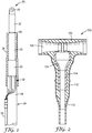
- Fig. 1 shows a power cable assembly 20 of the present invention which includes cable connector 22 (having aperture 23) attached to a cable 24.
- Cable 24 includes cable conductor 26 concentrically surrounded by cable insulation 28, cable insulation shield 30 (typically a conductive polymer), cable metallic ground 32 (which are shown as conductive wires, but may also be equally suitable materials such as conductive tape or solid metal conductors), and cable jacket 34.
- cable insulation 28, cable insulation shield 30, cable metallic ground 32, and cable jacket 34 are stripped back from an end of cable 24 to expose a portion of the underlying layer, down to cable conductor 26.
- Cable connector 22 is then attached to the exposed portion of cable conductor 26 by any suitable means, typically by crimping.
- any suitable means typically by crimping.
- cable metallic ground layer 32 comprises metal wires that are folded back, gathered, and attached to a small connector, which in turn is attached to an external conductor 38 (a separate cable).
- insulating sleeve 36 is applied to cable assembly 20 to insulate cable insulation shield 30 and cable metallic ground 32 from the outer semi-conductor layer of a connecting device 100 (shown in Fig. 2 ) when cable assembly 20 is inserted into connecting device 100.
- insulating sleeve 36 extends from the top of cable insulation layer 28 to, and over, a portion of cable jacket 34. External conductor 38, and, optionally, portions of the wires of cable metallic ground 32 extend beyond the edge of insulating sleeve 36.
- Insulating sleeve 36 may be made from any suitable material. It may comprise elastomeric material and may further be a cold-shrink sleeve. If it is a cold shrink sleeve, it may be made from any material suitable for cold-shrink applications. Most suitable are materials such as highly elastic rubber materials that have low permanent sets, such as ethylene propylene diene monomer (EPDM), elastomeric silicone, or hybrids thereof. Any suitable device that can electrically insulate cable assembly 20 from the semi-conductive layers of connecting device 100 may be used in place of insulating sleeve 36.
- EPDM ethylene propylene diene monomer
- the connecting device of the present invention may be any connector that is suited for use in a dead front terminal, that can accommodate a cable assembly with an isolated shield, and that is suitable for cross bonding as described herein.
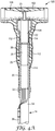
- Fig. 2 shows connecting device 100 which includes housing 102 that generally defines first chamber 104 and second chamber 106. First chamber 104 and second chamber 106 intersect such that the interior of first chamber 104 is in communication with the interior of second chamber 106. First and second chambers 104, 106 may intersect to form a general T-shape as shown in Fig. 2 or a general L-shape (not shown). Housing 102 further includes an outer semi-conductive layer 110, an intermediate insulating layer 112, and an inner semi-conductive layer 114. A portion of each of these layers partially forms the interior wall of first chamber 104.
- Housing 102 may be made from any material suitable for cold-shrink applications. Most suitable are materials such as highly elastic rubber materials that have a low permanent set, such as ethylene propylene diene monomer (EPDM), elastomeric silicone, or hybrids thereof.
- EPDM ethylene propylene diene monomer
- the semi-conductive and insulating materials may be made of the same or different types of materials. The semi-conductive and insulating materials may have differing degrees of conductivity and insulation based on the inherent properties of the materials used or based on additives added to the materials.
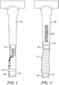
- a removable support core 200 is first loaded into first chamber 104, as illustrated in Fig. 3 . Once loaded, removable support core 200 extends from the end of the upper portion of first chamber 104 nearest second chamber 106 to beyond open end 109 of first chamber 104 through which cable assembly 20 is inserted. When loaded into first chamber 104, removable support core 200 radially expands first chamber 104 to an inner diameter greater than the outer diameter of the largest portion of cable assembly 20 that will be inserted into first chamber 104.
- Removable support core 200 may be made of any suitable material and in any suitable configuration, but typically consists of an extruded nylon or propylene ribbon that is helically wound. Removable support core 200 is removed from first chamber 104 by being unraveled. It is unraveled by pulling on a tab (not shown) extending from one end of the removable support core 200 and causing separation of the core along a helical score line or joint. Preferably, removable support core 200 is unraveled starting with the end in the upper portion of first chamber 104 nearest the second chamber 106 and ending with the end that extends beyond the open end 109 of first chamber 104. Unraveling removable support core 200 in this manner prevents the open end 109 of first chamber 104 from prematurely collapsing and obstructing the removal of removable support core 200.
- cable assembly 20 may be inserted into first chamber 104.
- cable connector 22 will include an aperture 23 at its free end. The free end is positioned in the intersection of the first and second chambers, 104, 106 with the remainder of the cable connector residing in first chamber 104.
- a mating device is inserted and holds the cable in place.
- Removable support core 200 may then be removed as described above to cause first chamber 104 to contract and form a tight seal around cable assembly 20.
- the portion of inner semi-conducting layer 114 comprising the interior wall of the first chamber 104 of the housing 102 makes intimate contact with the cable connector 22 of cable assembly 20.
- a second portion of the interior wall of first chamber 104 comprises intermediate insulating layer 112 and a third portion of the interior wall of first chamber 104 comprises outer semi-conducting layer 110.
- the third portion of the inner wall is prevented from making electrical contact with cable insulation shield 30 and with cable metallic ground layer 32. In the embodiment of Fig. 4A , this electrical contact is prevented by insulating sleeve 36.
- the portion of the interior wall of first chamber 104 comprising outer semi-conducting layer 110 preferably makes intimate contact with a portion of insulating sleeve 36 to prevent contaminants and/or moisture from entering the first chamber 104.
- An external conductor 38 is electrically connected to cable metallic ground layer 32 so cable metallic ground layer 32, can be cross bonded to the cable metallic ground layer 32 of another cable in a second dead front terminal.
- the layers of cable 24 are first removed generally as shown in Fig. 1 (and Fig. 4A ) so that a portion of each layer is exposed.
- the wires of the cable metallic ground layer 32 are pulled back and connected to the external conductor 38 with, e.g., a crimp connector.
- insulating sleeve 36 is placed over the exposed portions of the cable (except the cable conductor layer 26).
- the insulating sleeve 36 extends from the end of the cable insulation 28 adjacent the conductor 26 all the way to the cable jacket 34. It covers a portion of the cable jacket, metallic ground layer 32, and cable shield 30 to insulate the cable shield 30 and cable metallic ground 32 from outer semi-conductive layer 110 of connecting device 100.
- Fig. 4B shows an alternate embodiment of a dead front terminal of the present invention.
- open end 109 of first chamber 104 which is formed by outer semi-conductive layer 110, is located adjacent cable insulation shield 30 of cable 24 when the dead front terminal is assembled.
- Insulating sleeve 36 is configured to extend beyond open end 109 of first chamber 104 such that it covers more of cable insulation shield layer 30 than does semi-conductive layer 110, but is configured such that it does not cover cable metallic ground layer 32 or cable jacket 34.
- Cable metallic ground layer 32 may subsequently be covered by a protective layer, such as tape or an elastomeric sleeve, to prevent contact with contaminants and/or moisture.
- Fig. 4C shows yet another alternate embodiment of a dead front terminal of the present invention.
- the embodiment of 4C is similar to that of 4A except that insulating sleeve 36 does not extend from the top of cable insulation layer 28 to, and over, a portion of cable jacket 34. Instead, it extends from an intermediate portion of cable insulation layer 28 to and over, a portion of cable jacket 34.
- the means by which cable insulation shield 30 and cable metallic ground 32 are electrically insulated from the portion of first chamber 104 comprising outer semi-conductive layer 110 can be any suitable means such as, e.g., tape, mastic, a rigid tube, a crushable tube, a flexible tube, physical distance, etc.
- Cable insulation shield 30 and cable metallic ground 32 may be insulated by the same or different insulating means, which means may comprise one or more parts or sections. Any suitable combination of insulating means may be used so long as both cable insulation shield 30 and cable metallic ground layer 32 are adequately electrically insulated from outer semi-conductive layer 110.
- FIGs. 5 to 8 show a more detailed process by which a dead front terminal of the present invention is prepared for cross bonding.
- Fig. 5 shows the connecting device 100 installed on the cable assembly 20 with an optional mastic ring 120 to create an environmental seal once the optional environmental sealing tube ( Fig. 7 ) is applied.
- Fig. 6 shows external cable 38 covered by an optional layer of tape 37 and a ground wire 122 being attached to the outer semi-conductive layer 110 of the connecting device 100 by tape 39.
- Fig. 7 shows the application of an optional environmental sealing tube 124, which is a cold shrink tube in this case.
- the optional environmental sealing tube 124 covers a portion of connecting device 100, the previously exposed portion of insulating sleeve 36, part of external connector 38, and part of cable jacket 34.
- Fig. 8 shows the fully prepared terminal.
- External conductor 38 extends from the lower end of environmental sealing tube 124 and ground wire 122 extends from the upper end (closest to cable connector 22) of environmental sealing tube 124.
- splice cross bonding is done with three equal length sections of cable having cable metallic ground layers in different voltage phases wherein the cable sections are interrupted at one or more points by a splice connector.
- cross bonding typically consists of connecting the metallic ground layer of a cable coming into one splice connector to the metallic ground layer of a cable exiting a different splice connector wherein the metallic ground layers are in different voltage phases. This is illustrated in more detail in Fig.
- Fig 9 illustrates two sets of cross bonded splices installed along the entire cable length in order to create three equal smaller lengths of cables that are required to complete the phase shift canceling of the ground currents in the cable metallic ground layers along the entire length of cable. These two sets of splices are installed to create 3 equal lengths of cable so that the magnitude of the ground currents created in each section are equal which allows for phase cancelling when the metallic ground layers of the cables are cross bonded.
- the present invention relates to cross bonding dead front cable terminals.
- nine sections of cable are provided, 1A, 1B, 1C, 2A, 2B, 2C, 3A, 3B, and 3C.
- Each cable section is terminated at both ends by a connecting device.
- cable 1A is terminated by connecting devices 100A and 100A'
- cable 2A is terminated by connecting devices 200A and 200A'.
- the cable metallic ground layer of cable 1A which is terminated at one end by connecting device 100A', is connected to the cable metallic ground layer of cable 2B, which is terminated at one end by connecting device 200B;
- the cable metallic ground layer of cable 1B which is terminated at one end by connecting device 100B', is connected to the cable metallic ground layer of cable 2C, which is terminated at one end by connecting device 200C;
- the cable metallic ground layer of cable 1C which is terminated at one end by connecting device 100C', is connected to the cable metallic ground layer of cable 2A, which is terminated at one end by connecting device 200A.
- the cable metallic ground layer of cable 2A which is terminated at one end by connecting device 200A', is connected to the cable metallic ground layer of cable 3B, which is terminated at one end by connecting device 300B;
- the cable metallic ground layer of cable 2B which is terminated at one end by connecting device 200B', is connected to the cable metallic ground layer of cable 3C, which is terminated at one end by connecting device 300C;
- the cable metallic ground layer of cable 2C which is terminated at one end by connecting device 200C', is connected to the cable metallic ground layer of cable 3A, which is terminated at one end by connecting device 300A.
- Cross bonding the dead front terminals of the present invention is preferable over the previously used cross bonding splices because the connecting devices are above ground whereas the cable splices are below ground and are subject to moisture and mechanical damage. Furthermore, it is easier to locate and repair dead front terminals because they are above ground.
- An additional benefit of at least one embodiment of the present invention is that the connecting devices are separable and can serve as "test points" for very sensitive equipment to be utilized in the detection of the failed device(s).
Description
- This invention relates to a dead front cable terminal having an isolated shield. terminal is suitable for cross bonding.
- A dead front cable termination system typically includes a cable terminated with a metallic lug (i.e., cable connector), the cable connector and end portion of the cable being inserted into the housing of a connecting device, the cable connector being connected to a mating device within the confines of the housing. The housing needs to form a tight seal around the end portion of the cable to prevent contamination or corrosion of the connection.
- Long distribution underground cable circuits such as those used in wind farm power collection systems are subject to charge build up in the cable metallic shield layer on the cables. The charge build up can become so substantial that the cable has to be de-rated (i.e., operated at less than optimum) due to the heat generated by the ground current through the metallic shield layer. Heat is a contributing factor in cable degradation.
WO 98/45901 A1 - The present invention seeks to address the issue of charge build up by employing dead front terminal connectors that can be cross bonded.
- The present invention provides a first dead front terminal system according to claim 1.
- At least one embodiment of the present invention provides a system of cross bonded front terminals comprising: nine sections of cable, each having first and second ends, a first, a second, and a third cable section each having a second end comprising a cable assembly; a fourth, a fifth, and a sixth cable section each having first and second ends comprising a cable assembly; and a seventh, an eighth, and a ninth cable section each having a first end comprising a cable assembly; twelve connecting devices each comprising a first housing having an outer semi-conductive layer and a first chamber defined by at least one wall wherein the outer semi-conductive layer comprises a portion of at least one wall of the first chamber; at least a portion of each cable assembly residing in a first chamber of a housing of a connecting device, each cable assembly having an exposed cable insulation shield layer and cable metallic ground layer, each cable insulation shield layer and cable metallic ground layer being electrically insulated from the outer semi-conductor layer of the connecting device; wherein the cable metallic ground layer on the second end of the first cable section is electrically connected to the cable metallic ground layer on the first end of the fourth cable section; the cable metallic ground layer on the second end of the second cable section is electrically connected to the cable metallic ground layer on the first end of the fifth cable section; the cable metallic ground layer on the second end of the third cable section is electrically connected to the cable metallic ground layer on the first end of the sixth cable section; the cable metallic ground layer on the second end of the fourth cable section is electrically connected to the cable metallic ground layer on the first end of the seventh cable section; the cable metallic ground layer on the second end of the fifth cable section is electrically connected to the cable metallic ground layer on the first end of the eighth cable section; the cable metallic ground layer on the second end of the sixth cable section is electrically connected to the cable metallic ground layer on the first end of the ninth cable section; wherein the first, fourth, and seventh cable sections are in different voltage phases of a three-phase power system, the second, fifth, and eighth cable sections are in different voltage phases of a three-phase power system, and the third, sixth, and ninth cable section are in different voltage phases of a three-phase power system.
- The above summary of the present invention is not intended to describe each disclosed embodiment or every implementation of the present invention. The Figures and detailed description that follow below more particularly exemplify illustrative embodiments.
-
- Fig. 1
- depicts a partial cross-section of an example of a cable assembly of at least one embodiment of the present invention.
- Fig. 2
- depicts a cross-section of a connecting device of at least one embodiment of the present invention.
- Fig. 3
- depicts a partial cross-section of a connecting device of at least one embodiment of the present invention with a removable support core loaded in the connecting device.
- Figs. 4A-4C
- depict partial cross-sections of embodiments of dead front terminals of the present invention.
- Figs. 5 to 8
- depict steps in a process of preparing a dead front terminal according to at least one embodiment of the present invention.
- Fig. 9
- depicts prior art cross bonded splices.
- Fig. 10
- depicts a system of cross bonded dead front terminals according to at least one embodiment of the present invention.
- In the following detailed description of the preferred embodiments, reference is made to the accompanying drawings that form a part hereof. The accompanying drawings show, by way of illustration, specific embodiments in which the invention may be practiced. It is to be understood that other embodiments may be used, and structural or logical changes may be made without departing from the scope of the present invention. The following detailed description, therefore, is not to be taken in a limiting sense, and the scope of the invention is defined by the appended claims.
- Unless otherwise indicated, all numbers expressing feature sizes, amounts, and physical properties used in the specification and claims are to be understood as being modified in all instances by the term "about." Accordingly, unless indicated to the contrary, the numerical parameters set forth in the foregoing specification and attached claims are approximations that can vary depending upon the desired properties sought to be obtained by those skilled in the art utilizing the teachings disclosed herein. The use of numerical ranges by endpoints includes all numbers within that range (e.g. 1 to 5 includes 1, 1.5, 2, 2.75, 3, 3.80, 4, and 5) and any range within that range.
- In addition, directional terminology, such as "top," "bottom," "front," "back," "above," "below," etc., is used with reference to the orientation of the Figure(s) being described. Because components of embodiments can be positioned in a number of different orientations, the directional terminology is used for purposes of illustration and is in no way limiting. In general similar reference numbers are used for similar features in the various embodiments. Unless indicated otherwise, these similar features may comprise the same materials, have the same attributes, and serve the same or similar functions. Additional or optional features described for one embodiment may also be additional or optional features for other embodiments, even if not explicitly stated, where appropriate.
-
Fig. 1 shows apower cable assembly 20 of the present invention which includes cable connector 22 (having aperture 23) attached to acable 24.Cable 24 includescable conductor 26 concentrically surrounded bycable insulation 28, cable insulation shield 30 (typically a conductive polymer), cable metallic ground 32 (which are shown as conductive wires, but may also be equally suitable materials such as conductive tape or solid metal conductors), andcable jacket 34. To formcable assembly 20, each of thecable insulation 28,cable insulation shield 30, cablemetallic ground 32, andcable jacket 34 are stripped back from an end ofcable 24 to expose a portion of the underlying layer, down tocable conductor 26.Cable connector 22 is then attached to the exposed portion ofcable conductor 26 by any suitable means, typically by crimping. In the embodiment ofFig. 1 , cablemetallic ground layer 32 comprises metal wires that are folded back, gathered, and attached to a small connector, which in turn is attached to an external conductor 38 (a separate cable). In the embodiment ofFig. 1 ,insulating sleeve 36 is applied tocable assembly 20 to insulatecable insulation shield 30 and cablemetallic ground 32 from the outer semi-conductor layer of a connecting device 100 (shown inFig. 2 ) whencable assembly 20 is inserted into connectingdevice 100. In the embodiment ofFig. 1 ,insulating sleeve 36 extends from the top ofcable insulation layer 28 to, and over, a portion ofcable jacket 34.External conductor 38, and, optionally, portions of the wires of cablemetallic ground 32 extend beyond the edge ofinsulating sleeve 36. - Insulating
sleeve 36 may be made from any suitable material. It may comprise elastomeric material and may further be a cold-shrink sleeve. If it is a cold shrink sleeve, it may be made from any material suitable for cold-shrink applications. Most suitable are materials such as highly elastic rubber materials that have low permanent sets, such as ethylene propylene diene monomer (EPDM), elastomeric silicone, or hybrids thereof. Any suitable device that can electrically insulatecable assembly 20 from the semi-conductive layers of connectingdevice 100 may be used in place ofinsulating sleeve 36. - The connecting device of the present invention may be any connector that is suited for use in a dead front terminal, that can accommodate a cable assembly with an isolated shield, and that is suitable for cross bonding as described herein.
Fig. 2 shows connectingdevice 100 which includeshousing 102 that generally definesfirst chamber 104 andsecond chamber 106.First chamber 104 andsecond chamber 106 intersect such that the interior offirst chamber 104 is in communication with the interior ofsecond chamber 106. First andsecond chambers Fig. 2 or a general L-shape (not shown).Housing 102 further includes an outersemi-conductive layer 110, an intermediateinsulating layer 112, and an innersemi-conductive layer 114. A portion of each of these layers partially forms the interior wall offirst chamber 104. -
Housing 102 may be made from any material suitable for cold-shrink applications. Most suitable are materials such as highly elastic rubber materials that have a low permanent set, such as ethylene propylene diene monomer (EPDM), elastomeric silicone, or hybrids thereof. The semi-conductive and insulating materials may be made of the same or different types of materials. The semi-conductive and insulating materials may have differing degrees of conductivity and insulation based on the inherent properties of the materials used or based on additives added to the materials. - To enable
cable assembly 20 to be inserted intofirst chamber 104 of connectingdevice 100, aremovable support core 200 is first loaded intofirst chamber 104, as illustrated inFig. 3 . Once loaded,removable support core 200 extends from the end of the upper portion offirst chamber 104 nearestsecond chamber 106 to beyondopen end 109 offirst chamber 104 through whichcable assembly 20 is inserted. When loaded intofirst chamber 104,removable support core 200 radially expandsfirst chamber 104 to an inner diameter greater than the outer diameter of the largest portion ofcable assembly 20 that will be inserted intofirst chamber 104. -
Removable support core 200 may be made of any suitable material and in any suitable configuration, but typically consists of an extruded nylon or propylene ribbon that is helically wound.Removable support core 200 is removed fromfirst chamber 104 by being unraveled. It is unraveled by pulling on a tab (not shown) extending from one end of theremovable support core 200 and causing separation of the core along a helical score line or joint. Preferably,removable support core 200 is unraveled starting with the end in the upper portion offirst chamber 104 nearest thesecond chamber 106 and ending with the end that extends beyond theopen end 109 offirst chamber 104. Unravelingremovable support core 200 in this manner prevents theopen end 109 offirst chamber 104 from prematurely collapsing and obstructing the removal ofremovable support core 200. - Once the removable support core has been loaded into the
first chamber 104,cable assembly 20 may be inserted intofirst chamber 104. Typically,cable connector 22 will include anaperture 23 at its free end. The free end is positioned in the intersection of the first and second chambers, 104, 106 with the remainder of the cable connector residing infirst chamber 104. Once the cable assembly is correctly positioned, a mating device is inserted and holds the cable in place.Removable support core 200 may then be removed as described above to causefirst chamber 104 to contract and form a tight seal aroundcable assembly 20. - In the embodiment of
Fig. 4A , when the dead front terminal is assembled, the portion of innersemi-conducting layer 114 comprising the interior wall of thefirst chamber 104 of thehousing 102 makes intimate contact with thecable connector 22 ofcable assembly 20. A second portion of the interior wall offirst chamber 104 comprises intermediate insulatinglayer 112 and a third portion of the interior wall offirst chamber 104 comprises outersemi-conducting layer 110. To accomplish shield isolation and cross bonding, the third portion of the inner wall is prevented from making electrical contact withcable insulation shield 30 and with cablemetallic ground layer 32. In the embodiment ofFig. 4A , this electrical contact is prevented by insulatingsleeve 36. The portion of the interior wall offirst chamber 104 comprising outersemi-conducting layer 110 preferably makes intimate contact with a portion of insulatingsleeve 36 to prevent contaminants and/or moisture from entering thefirst chamber 104. Anexternal conductor 38 is electrically connected to cablemetallic ground layer 32 so cablemetallic ground layer 32, can be cross bonded to the cablemetallic ground layer 32 of another cable in a second dead front terminal. - To create the device of
Fig. 4A , the layers ofcable 24 are first removed generally as shown inFig. 1 (andFig. 4A ) so that a portion of each layer is exposed. The wires of the cablemetallic ground layer 32 are pulled back and connected to theexternal conductor 38 with, e.g., a crimp connector. Then insulatingsleeve 36 is placed over the exposed portions of the cable (except the cable conductor layer 26). In this embodiment, the insulatingsleeve 36 extends from the end of thecable insulation 28 adjacent theconductor 26 all the way to thecable jacket 34. It covers a portion of the cable jacket,metallic ground layer 32, andcable shield 30 to insulate thecable shield 30 and cablemetallic ground 32 from outersemi-conductive layer 110 of connectingdevice 100. -
Fig. 4B shows an alternate embodiment of a dead front terminal of the present invention. In the embodiment ofFig. 4B ,open end 109 offirst chamber 104, which is formed byouter semi-conductive layer 110, is located adjacentcable insulation shield 30 ofcable 24 when the dead front terminal is assembled. Insulatingsleeve 36 is configured to extend beyondopen end 109 offirst chamber 104 such that it covers more of cableinsulation shield layer 30 than doessemi-conductive layer 110, but is configured such that it does not cover cablemetallic ground layer 32 orcable jacket 34. Cablemetallic ground layer 32 may subsequently be covered by a protective layer, such as tape or an elastomeric sleeve, to prevent contact with contaminants and/or moisture. -
Fig. 4C shows yet another alternate embodiment of a dead front terminal of the present invention. The embodiment of 4C is similar to that of 4A except that insulatingsleeve 36 does not extend from the top ofcable insulation layer 28 to, and over, a portion ofcable jacket 34. Instead, it extends from an intermediate portion ofcable insulation layer 28 to and over, a portion ofcable jacket 34. - As can be seen from the embodiments of
Figs. 4A-4C , the means by whichcable insulation shield 30 and cablemetallic ground 32 are electrically insulated from the portion offirst chamber 104 comprising outersemi-conductive layer 110 can be any suitable means such as, e.g., tape, mastic, a rigid tube, a crushable tube, a flexible tube, physical distance, etc.Cable insulation shield 30 and cablemetallic ground 32 may be insulated by the same or different insulating means, which means may comprise one or more parts or sections. Any suitable combination of insulating means may be used so long as bothcable insulation shield 30 and cablemetallic ground layer 32 are adequately electrically insulated from outersemi-conductive layer 110. -
Figs. 5 to 8 show a more detailed process by which a dead front terminal of the present invention is prepared for cross bonding.Fig. 5 shows the connectingdevice 100 installed on thecable assembly 20 with anoptional mastic ring 120 to create an environmental seal once the optional environmental sealing tube (Fig. 7 ) is applied.Fig. 6 showsexternal cable 38 covered by an optional layer oftape 37 and aground wire 122 being attached to theouter semi-conductive layer 110 of the connectingdevice 100 bytape 39.Fig. 7 shows the application of an optionalenvironmental sealing tube 124, which is a cold shrink tube in this case. The optionalenvironmental sealing tube 124 covers a portion of connectingdevice 100, the previously exposed portion of insulatingsleeve 36, part ofexternal connector 38, and part ofcable jacket 34.Fig. 8 shows the fully prepared terminal.External conductor 38 extends from the lower end ofenvironmental sealing tube 124 andground wire 122 extends from the upper end (closest to cable connector 22) ofenvironmental sealing tube 124. - Prior to the present invention, only cross bonding of splices was known. Typically, splice cross bonding is done with three equal length sections of cable having cable metallic ground layers in different voltage phases wherein the cable sections are interrupted at one or more points by a splice connector. When cross bonding is done with splices, it typically consists of connecting the metallic ground layer of a cable coming into one splice connector to the metallic ground layer of a cable exiting a different splice connector wherein the metallic ground layers are in different voltage phases. This is illustrated in more detail in
Fig. 9 in which the metallic ground layer on the first section (to the left of each splice) of cable A is connected to the metallic ground layer on the second section (to the right of each splice) of cable B; the cable metallic ground layer on the first section of cable B is connected to the cable metallic ground layer on the second section of cable C; and the cable metallic ground layer on the first section of cable C is connected to the cable metallic ground layer on the second section of cable A. -
Fig 9 illustrates two sets of cross bonded splices installed along the entire cable length in order to create three equal smaller lengths of cables that are required to complete the phase shift canceling of the ground currents in the cable metallic ground layers along the entire length of cable. These two sets of splices are installed to create 3 equal lengths of cable so that the magnitude of the ground currents created in each section are equal which allows for phase cancelling when the metallic ground layers of the cables are cross bonded. - Instead of cable splice connectors, the present invention relates to cross bonding dead front cable terminals. For example, as shown in
Fig. 10 , nine sections of cable are provided, 1A, 1B, 1C, 2A, 2B, 2C, 3A, 3B, and 3C. Each cable section is terminated at both ends by a connecting device. For example,cable 1A is terminated by connectingdevices cable 2A is terminated by connectingdevices cable 1A, which is terminated at one end by connectingdevice 100A', is connected to the cable metallic ground layer ofcable 2B, which is terminated at one end by connectingdevice 200B; the cable metallic ground layer ofcable 1B, which is terminated at one end by connectingdevice 100B', is connected to the cable metallic ground layer ofcable 2C, which is terminated at one end by connectingdevice 200C; and the cable metallic ground layer ofcable 1C, which is terminated at one end by connectingdevice 100C', is connected to the cable metallic ground layer ofcable 2A, which is terminated at one end by connectingdevice 200A. Similarly, at a second junction box, the cable metallic ground layer ofcable 2A, which is terminated at one end by connectingdevice 200A', is connected to the cable metallic ground layer ofcable 3B, which is terminated at one end by connectingdevice 300B; the cable metallic ground layer ofcable 2B, which is terminated at one end by connectingdevice 200B', is connected to the cable metallic ground layer ofcable 3C, which is terminated at one end by connectingdevice 300C; and the cable metallic ground layer ofcable 2C, which is terminated at one end by connectingdevice 200C', is connected to the cable metallic ground layer ofcable 3A, which is terminated at one end by connectingdevice 300A. - As with splices, when cross bonding dead front terminals, it is preferable to have two sets of cross bonded terminals installed along the entire cable length in order to create 3 equal smaller lengths of cables that are required to complete the phase shift cancelling of the ground currents in the cable metallic ground layers along the entire length of cable. These two sets of terminals are installed to create 3 equal lengths of cable so that the magnitude of the ground currents created in each section are equal with allows for phase cancelling when the metallic ground layers of the cables are cross bonded.
- Prior to the present invention, in applications such as wind farms, which require long distribution cable circuits, typically greater than 304.8 meters (1000 feet), splices were created in the cables for the purpose of cross bonding. It was not known to cross bond dead front terminals. Prior to the present invention, a significant impediment to cross bonding dead front terminals was the inability to electrically isolate the cable metallic ground (and cable insulation shield layer) from the outer semi-conductor layer of the connecting devices. At least one embodiment of the present invention solves that problem. By cross bonding the cables at the dead front terminals, as is done in the present invention, the need to create splices for cross bonding in long distribution cable circuits can be eliminated. Cross bonding the dead front terminals of the present invention is preferable over the previously used cross bonding splices because the connecting devices are above ground whereas the cable splices are below ground and are subject to moisture and mechanical damage. Furthermore, it is easier to locate and repair dead front terminals because they are above ground. An additional benefit of at least one embodiment of the present invention is that the connecting devices are separable and can serve as "test points" for very sensitive equipment to be utilized in the detection of the failed device(s).
- Although specific embodiments have been illustrated and described herein for purposes of description of the preferred embodiment, it will be appreciated by those of ordinary skill in the art that a wide variety of alternate and/or equivalent implementations may be substituted for the specific embodiments shown and described without departing from the scope of the present invention as disclosed in the appended claims.
Claims (8)
- A first dead front terminal system comprising:a first connecting device (100) comprising a first housing (102) having an outer semi-conductive layer (110) and a first chamber (104) defined by at least one wall wherein the outer semi-conductive layer (110) comprises a portion of at least one wall of the first chamber (104),a first cable assembly (20) having an exposed cable insulation shield layer (30) and an exposed cable metallic ground layer (32), at least a portion of the first cable assembly (20) positioned within the first chamber (104) of the first connecting device (100),characterized in that the first connecting device (100) includes a removable support core (200) to radially expand the first chamber (104) and that extends from an end of an upper portion of the first chamber (104) to beyond an open end of the first chamber (104) through which the first cable assembly (20) is inserted, comprising a helically wound ribbon that can be unraveled to cause the first chamber (104) to contract and form a tight seal around the first cable assembly (20) after the first cable assembly (20) is inserted within the first chamber (104) such that, when the first dead front terminal system is assembled, the cable insulation shield layer (30) and the cable metallic ground layer (32) are electrically insulated and isolated from the outer semi-conductive layer (110) of the connecting device (100),
wherein the cable metallic ground layer (32) is adapted to be electrically connected to a first external conductor (38) and
wherein both of the cable insulation shield layer (30) and the cable metallic ground layer (32) are electrically insulated and isolated from the outer semi-conductor layer (110) of the connecting device (100) by an insulating sleeve (36). - The system of claim 1 wherein one or both of the cable insulation shield layer (30) and the cable metallic ground layer (32) is located in the first chamber (104) of the connecting device housing (102).
- The system of claim 1 or 2 wherein the insulating sleeve (36) is an elastomeric sleeve.
- A system of cross bonded dead front terminals comprising the first dead front terminal system of claim 1 or 2 wherein the first external conductor (38) is electrically connected to a second external conductor (38) that is electrically connected to a cable metallic ground layer (32) of a second cable assembly (20), at least a portion of the second cable assembly being positioned within a first chamber (104) of a second housing of a second connecting device (100) of a second dead front terminal.
- The system of claim 4 further comprising a third dead front terminal comprising a third connecting device (100) and a third cable assembly (20) at least a portion of which third cable assembly is positioned within a first chamber (104) of a third housing (102) of the third connecting device and a third external conductor (28) electrically connected to a cable metallic ground layer (32) of the third cable assembly and to a fourth external conductor (28) that is electrically connected to a cable metallic ground layer (32) of a fourth cable assembly (20), at least a portion of the fourth cable assembly being positioned within a first chamber (104) of a fourth housing (102) of a fourth connecting device (100) of a fourth dead front terminal.
- The system of claim 5 further comprising a fifth dead front terminal comprising a fifth connecting device (100) and a fifth cable assembly (20) at least a portion of which fifth cable assembly is positioned within a first chamber (104) of a fifth housing (102) of the fifth connecting device and a fifth external conductor (28) electrically connected to a cable metallic ground layer (32) of the fifth cable assembly and to a sixth external conductor (38) that is electrically connected to a cable metallic ground layer (32) of a sixth cable assembly (20), at least a portion of the sixth cable assembly being positioned within a first chamber (104) of a sixth housing (102) of a sixth connecting device of a sixth dead front terminal.
- The system of claim 6 wherein the first and second cables of the first and second cable assemblies, respectively, are in different voltage phases of a three-phase power system, the third and fourth cables of the third and fourth cable assemblies, respectively, are in different voltage phases of a three-phase power system, and the fifth and sixth cables of the fifth and sixth cable assemblies, respectively, are in different voltage phases of a three-phase power system.
- A system of cross bonded dead front terminals comprising:nine sections of cable (1A, 1B, 1C, 2A, 2B, 2C, 3A, 3B, 3C), each having first and second ends,a first, a second, and a third cable section each having a second end (100A', 100B', 100C') comprising a cable assembly (20) of the system of claim 1; a fourth, a fifth, and a sixth cable section each having a first end (200A, 200B, 200C) and a second end (200A', 200B', 200C') comprising a cable assembly (20); and a seventh, an eighth, and a ninth cable section each having a first end (300A, 300B, 300C) comprising a cable assembly (20) of the system of claim 1;twelve dead front terminal systems according to claim 1;wherein the cable metallic ground layer on the second end of the first cable section (100A') is electrically connected to the cable metallic ground layer on the first end of the fourth cable section (200B); the cable metallic ground layer on the second end of the second cable section (100B') is electrically connected to the cable metallic ground layer on the first end of the fifth cable section (200C); the cable metallic ground layer on the second end of the third cable section (100C') is electrically connected to the cable metallic ground layer on the first end of the sixth cable section (200A); the cable metallic ground layer on the second end of the fourth cable section (200B') is electrically connected to the cable metallic ground layer on the first end of the seventh cable section (300C); the cable metallic ground layer on the second end of the fifth cable section (200C') is electrically connected to the cable metallic ground layer on the first end of the eighth cable section (300A); the cable metallic ground layer on the second end of the sixth cable section (200A') is electrically connected to the cable metallic ground layer on the first end of the ninth cable section (300B);wherein the first, fourth, and seventh cable sections are in different voltage phases of a three-phase power system, the second, fifth, and eighth cable sections are in different voltage phases of a three-phase power system, the third, sixth, and ninth cable section are in different voltage phases of a three-phase power system.
Applications Claiming Priority (2)
| Application Number | Priority Date | Filing Date | Title |
|---|---|---|---|
| US201161488589P | 2011-05-20 | 2011-05-20 | |
| PCT/US2012/038274 WO2012162076A1 (en) | 2011-05-20 | 2012-05-17 | Dead front cable terminal with isolated shield |
Publications (2)
| Publication Number | Publication Date |
|---|---|
| EP2710683A1 EP2710683A1 (en) | 2014-03-26 |
| EP2710683B1 true EP2710683B1 (en) | 2019-08-28 |
Family
ID=46208162
Family Applications (1)
| Application Number | Title | Priority Date | Filing Date |
|---|---|---|---|
| EP12725569.3A Active EP2710683B1 (en) | 2011-05-20 | 2012-05-17 | Dead front cable terminal with isolated shield |
Country Status (8)
| Country | Link |
|---|---|
| EP (1) | EP2710683B1 (en) |
| JP (1) | JP6038892B2 (en) |
| KR (1) | KR20140034217A (en) |
| CA (1) | CA2835889C (en) |
| MX (1) | MX2013013254A (en) |
| RU (1) | RU2576248C2 (en) |
| TW (1) | TW201310833A (en) |
| WO (1) | WO2012162076A1 (en) |
Families Citing this family (1)
| Publication number | Priority date | Publication date | Assignee | Title |
|---|---|---|---|---|
| US9504195B2 (en) * | 2014-05-16 | 2016-11-22 | Tyco Electronics Corporation | Cover assemblies, kits and methods for covering electrical cables and connections |
Citations (4)
| Publication number | Priority date | Publication date | Assignee | Title |
|---|---|---|---|---|
| US5098752A (en) * | 1990-04-17 | 1992-03-24 | Raychem Corporation | Recoverable elastomeric sleeve and method for installation and use |
| US5230640A (en) * | 1991-03-12 | 1993-07-27 | Cables Pirelli | Connecting device for one or two electric cables, and process for mounting this device on the end of the cable or cables |
| WO1998045901A1 (en) * | 1997-04-07 | 1998-10-15 | Abb Ab | Connector |
| EP1696517A1 (en) * | 2005-02-25 | 2006-08-30 | Nkt cables GmbH | Connector assembly for devices or cables to an electric installation |
Family Cites Families (3)
| Publication number | Priority date | Publication date | Assignee | Title |
|---|---|---|---|---|
| GB8303462D0 (en) * | 1983-02-08 | 1983-03-16 | Raychem Gmbh | Electrical stress control |
| CN101340035B (en) * | 2007-07-02 | 2010-08-25 | 3M创新有限公司 | Adapter, cable connector having the adapter and cable connector component |
| CN102460876A (en) * | 2009-05-01 | 2012-05-16 | 3M创新有限公司 | Cold-shrink separable connector |
-
2012
- 2012-05-17 WO PCT/US2012/038274 patent/WO2012162076A1/en active Application Filing
- 2012-05-17 CA CA2835889A patent/CA2835889C/en not_active Expired - Fee Related
- 2012-05-17 KR KR1020137032871A patent/KR20140034217A/en not_active Application Discontinuation
- 2012-05-17 RU RU2013156464/07A patent/RU2576248C2/en not_active IP Right Cessation
- 2012-05-17 MX MX2013013254A patent/MX2013013254A/en active IP Right Grant
- 2012-05-17 EP EP12725569.3A patent/EP2710683B1/en active Active
- 2012-05-17 JP JP2014511518A patent/JP6038892B2/en not_active Expired - Fee Related
- 2012-05-18 TW TW101117877A patent/TW201310833A/en unknown
Patent Citations (4)
| Publication number | Priority date | Publication date | Assignee | Title |
|---|---|---|---|---|
| US5098752A (en) * | 1990-04-17 | 1992-03-24 | Raychem Corporation | Recoverable elastomeric sleeve and method for installation and use |
| US5230640A (en) * | 1991-03-12 | 1993-07-27 | Cables Pirelli | Connecting device for one or two electric cables, and process for mounting this device on the end of the cable or cables |
| WO1998045901A1 (en) * | 1997-04-07 | 1998-10-15 | Abb Ab | Connector |
| EP1696517A1 (en) * | 2005-02-25 | 2006-08-30 | Nkt cables GmbH | Connector assembly for devices or cables to an electric installation |
Also Published As
| Publication number | Publication date |
|---|---|
| TW201310833A (en) | 2013-03-01 |
| WO2012162076A1 (en) | 2012-11-29 |
| RU2013156464A (en) | 2015-06-27 |
| CA2835889C (en) | 2019-06-04 |
| JP2014517471A (en) | 2014-07-17 |
| JP6038892B2 (en) | 2016-12-07 |
| KR20140034217A (en) | 2014-03-19 |
| CA2835889A1 (en) | 2012-11-29 |
| CN103548210A (en) | 2014-01-29 |
| EP2710683A1 (en) | 2014-03-26 |
| RU2576248C2 (en) | 2016-02-27 |
| MX2013013254A (en) | 2014-01-08 |
Similar Documents
| Publication | Publication Date | Title |
|---|---|---|
| US9960530B2 (en) | Terminal connection device for a power cable | |
| US9504195B2 (en) | Cover assemblies, kits and methods for covering electrical cables and connections | |
| US8889989B2 (en) | Elastomeric cable adapters for power transmission cables and cover assemblies and methods including the same | |
| US8866014B2 (en) | Dead front cable terminal with isolated shield | |
| EP2510582B1 (en) | Biasing connector | |
| TW201513468A (en) | Cable connection device | |
| WO2019055209A1 (en) | Cover system and method for covering an electrical connection | |
| JP4615258B2 (en) | Power cable termination connection and assembly method | |
| EP2710683B1 (en) | Dead front cable terminal with isolated shield | |
| US10389103B2 (en) | Breakout boot assemblies and methods for covering electrical cables and connections | |
| CN209929940U (en) | High-voltage crosslinked polyethylene insulated cable molding type insulated joint | |
| CN203434305U (en) | Power cable grounding device and power cable system | |
| JP2005354843A (en) | Y-branch connection structure for power cable and y-branch connection method |
Legal Events
| Date | Code | Title | Description |
|---|---|---|---|
| PUAI | Public reference made under article 153(3) epc to a published international application that has entered the european phase |
Free format text: ORIGINAL CODE: 0009012 |
|
| 17P | Request for examination filed |
Effective date: 20131120 |
|
| AK | Designated contracting states |
Kind code of ref document: A1 Designated state(s): AL AT BE BG CH CY CZ DE DK EE ES FI FR GB GR HR HU IE IS IT LI LT LU LV MC MK MT NL NO PL PT RO RS SE SI SK SM TR |
|
| DAX | Request for extension of the european patent (deleted) | ||
| 17Q | First examination report despatched |
Effective date: 20150430 |
|
| STAA | Information on the status of an ep patent application or granted ep patent |
Free format text: STATUS: EXAMINATION IS IN PROGRESS |
|
| REG | Reference to a national code |
Ref country code: DE Ref legal event code: R079 Ref document number: 602012063358 Country of ref document: DE Free format text: PREVIOUS MAIN CLASS: H01R0013530000 Ipc: H01R0004700000 |
|
| RIC1 | Information provided on ipc code assigned before grant |
Ipc: H01R 4/70 20060101AFI20190205BHEP Ipc: H01R 13/53 20060101ALI20190205BHEP Ipc: H01R 43/18 20060101ALI20190205BHEP |
|
| GRAP | Despatch of communication of intention to grant a patent |
Free format text: ORIGINAL CODE: EPIDOSNIGR1 |
|
| STAA | Information on the status of an ep patent application or granted ep patent |
Free format text: STATUS: GRANT OF PATENT IS INTENDED |
|
| INTG | Intention to grant announced |
Effective date: 20190318 |
|
| GRAS | Grant fee paid |
Free format text: ORIGINAL CODE: EPIDOSNIGR3 |
|
| GRAA | (expected) grant |
Free format text: ORIGINAL CODE: 0009210 |
|
| STAA | Information on the status of an ep patent application or granted ep patent |
Free format text: STATUS: THE PATENT HAS BEEN GRANTED |
|
| AK | Designated contracting states |
Kind code of ref document: B1 Designated state(s): AL AT BE BG CH CY CZ DE DK EE ES FI FR GB GR HR HU IE IS IT LI LT LU LV MC MK MT NL NO PL PT RO RS SE SI SK SM TR |
|
| REG | Reference to a national code |
Ref country code: GB Ref legal event code: FG4D |
|
| REG | Reference to a national code |
Ref country code: CH Ref legal event code: EP |
|
| REG | Reference to a national code |
Ref country code: DE Ref legal event code: R096 Ref document number: 602012063358 Country of ref document: DE |
|
| REG | Reference to a national code |
Ref country code: AT Ref legal event code: REF Ref document number: 1173561 Country of ref document: AT Kind code of ref document: T Effective date: 20190915 |
|
| REG | Reference to a national code |
Ref country code: IE Ref legal event code: FG4D |
|
| REG | Reference to a national code |
Ref country code: NL Ref legal event code: MP Effective date: 20190828 |
|
| REG | Reference to a national code |
Ref country code: LT Ref legal event code: MG4D |
|
| PG25 | Lapsed in a contracting state [announced via postgrant information from national office to epo] |
Ref country code: FI Free format text: LAPSE BECAUSE OF FAILURE TO SUBMIT A TRANSLATION OF THE DESCRIPTION OR TO PAY THE FEE WITHIN THE PRESCRIBED TIME-LIMIT Effective date: 20190828 Ref country code: PT Free format text: LAPSE BECAUSE OF FAILURE TO SUBMIT A TRANSLATION OF THE DESCRIPTION OR TO PAY THE FEE WITHIN THE PRESCRIBED TIME-LIMIT Effective date: 20191230 Ref country code: NO Free format text: LAPSE BECAUSE OF FAILURE TO SUBMIT A TRANSLATION OF THE DESCRIPTION OR TO PAY THE FEE WITHIN THE PRESCRIBED TIME-LIMIT Effective date: 20191128 Ref country code: HR Free format text: LAPSE BECAUSE OF FAILURE TO SUBMIT A TRANSLATION OF THE DESCRIPTION OR TO PAY THE FEE WITHIN THE PRESCRIBED TIME-LIMIT Effective date: 20190828 Ref country code: LT Free format text: LAPSE BECAUSE OF FAILURE TO SUBMIT A TRANSLATION OF THE DESCRIPTION OR TO PAY THE FEE WITHIN THE PRESCRIBED TIME-LIMIT Effective date: 20190828 Ref country code: SE Free format text: LAPSE BECAUSE OF FAILURE TO SUBMIT A TRANSLATION OF THE DESCRIPTION OR TO PAY THE FEE WITHIN THE PRESCRIBED TIME-LIMIT Effective date: 20190828 Ref country code: NL Free format text: LAPSE BECAUSE OF FAILURE TO SUBMIT A TRANSLATION OF THE DESCRIPTION OR TO PAY THE FEE WITHIN THE PRESCRIBED TIME-LIMIT Effective date: 20190828 Ref country code: BG Free format text: LAPSE BECAUSE OF FAILURE TO SUBMIT A TRANSLATION OF THE DESCRIPTION OR TO PAY THE FEE WITHIN THE PRESCRIBED TIME-LIMIT Effective date: 20191128 |
|
| PG25 | Lapsed in a contracting state [announced via postgrant information from national office to epo] |
Ref country code: GR Free format text: LAPSE BECAUSE OF FAILURE TO SUBMIT A TRANSLATION OF THE DESCRIPTION OR TO PAY THE FEE WITHIN THE PRESCRIBED TIME-LIMIT Effective date: 20191129 Ref country code: LV Free format text: LAPSE BECAUSE OF FAILURE TO SUBMIT A TRANSLATION OF THE DESCRIPTION OR TO PAY THE FEE WITHIN THE PRESCRIBED TIME-LIMIT Effective date: 20190828 Ref country code: AL Free format text: LAPSE BECAUSE OF FAILURE TO SUBMIT A TRANSLATION OF THE DESCRIPTION OR TO PAY THE FEE WITHIN THE PRESCRIBED TIME-LIMIT Effective date: 20190828 Ref country code: RS Free format text: LAPSE BECAUSE OF FAILURE TO SUBMIT A TRANSLATION OF THE DESCRIPTION OR TO PAY THE FEE WITHIN THE PRESCRIBED TIME-LIMIT Effective date: 20190828 Ref country code: IS Free format text: LAPSE BECAUSE OF FAILURE TO SUBMIT A TRANSLATION OF THE DESCRIPTION OR TO PAY THE FEE WITHIN THE PRESCRIBED TIME-LIMIT Effective date: 20191228 Ref country code: ES Free format text: LAPSE BECAUSE OF FAILURE TO SUBMIT A TRANSLATION OF THE DESCRIPTION OR TO PAY THE FEE WITHIN THE PRESCRIBED TIME-LIMIT Effective date: 20190828 |
|
| REG | Reference to a national code |
Ref country code: AT Ref legal event code: MK05 Ref document number: 1173561 Country of ref document: AT Kind code of ref document: T Effective date: 20190828 |
|
| PG25 | Lapsed in a contracting state [announced via postgrant information from national office to epo] |
Ref country code: TR Free format text: LAPSE BECAUSE OF FAILURE TO SUBMIT A TRANSLATION OF THE DESCRIPTION OR TO PAY THE FEE WITHIN THE PRESCRIBED TIME-LIMIT Effective date: 20190828 |
|
| PG25 | Lapsed in a contracting state [announced via postgrant information from national office to epo] |
Ref country code: RO Free format text: LAPSE BECAUSE OF FAILURE TO SUBMIT A TRANSLATION OF THE DESCRIPTION OR TO PAY THE FEE WITHIN THE PRESCRIBED TIME-LIMIT Effective date: 20190828 Ref country code: IT Free format text: LAPSE BECAUSE OF FAILURE TO SUBMIT A TRANSLATION OF THE DESCRIPTION OR TO PAY THE FEE WITHIN THE PRESCRIBED TIME-LIMIT Effective date: 20190828 Ref country code: PL Free format text: LAPSE BECAUSE OF FAILURE TO SUBMIT A TRANSLATION OF THE DESCRIPTION OR TO PAY THE FEE WITHIN THE PRESCRIBED TIME-LIMIT Effective date: 20190828 Ref country code: AT Free format text: LAPSE BECAUSE OF FAILURE TO SUBMIT A TRANSLATION OF THE DESCRIPTION OR TO PAY THE FEE WITHIN THE PRESCRIBED TIME-LIMIT Effective date: 20190828 Ref country code: DK Free format text: LAPSE BECAUSE OF FAILURE TO SUBMIT A TRANSLATION OF THE DESCRIPTION OR TO PAY THE FEE WITHIN THE PRESCRIBED TIME-LIMIT Effective date: 20190828 Ref country code: EE Free format text: LAPSE BECAUSE OF FAILURE TO SUBMIT A TRANSLATION OF THE DESCRIPTION OR TO PAY THE FEE WITHIN THE PRESCRIBED TIME-LIMIT Effective date: 20190828 |
|
| PG25 | Lapsed in a contracting state [announced via postgrant information from national office to epo] |
Ref country code: CZ Free format text: LAPSE BECAUSE OF FAILURE TO SUBMIT A TRANSLATION OF THE DESCRIPTION OR TO PAY THE FEE WITHIN THE PRESCRIBED TIME-LIMIT Effective date: 20190828 Ref country code: SM Free format text: LAPSE BECAUSE OF FAILURE TO SUBMIT A TRANSLATION OF THE DESCRIPTION OR TO PAY THE FEE WITHIN THE PRESCRIBED TIME-LIMIT Effective date: 20190828 Ref country code: SK Free format text: LAPSE BECAUSE OF FAILURE TO SUBMIT A TRANSLATION OF THE DESCRIPTION OR TO PAY THE FEE WITHIN THE PRESCRIBED TIME-LIMIT Effective date: 20190828 Ref country code: IS Free format text: LAPSE BECAUSE OF FAILURE TO SUBMIT A TRANSLATION OF THE DESCRIPTION OR TO PAY THE FEE WITHIN THE PRESCRIBED TIME-LIMIT Effective date: 20200224 |
|
| REG | Reference to a national code |
Ref country code: DE Ref legal event code: R097 Ref document number: 602012063358 Country of ref document: DE |
|
| PLBE | No opposition filed within time limit |
Free format text: ORIGINAL CODE: 0009261 |
|
| STAA | Information on the status of an ep patent application or granted ep patent |
Free format text: STATUS: NO OPPOSITION FILED WITHIN TIME LIMIT |
|
| PG2D | Information on lapse in contracting state deleted |
Ref country code: IS |
|
| 26N | No opposition filed |
Effective date: 20200603 |
|
| PG25 | Lapsed in a contracting state [announced via postgrant information from national office to epo] |
Ref country code: SI Free format text: LAPSE BECAUSE OF FAILURE TO SUBMIT A TRANSLATION OF THE DESCRIPTION OR TO PAY THE FEE WITHIN THE PRESCRIBED TIME-LIMIT Effective date: 20190828 |
|
| PG25 | Lapsed in a contracting state [announced via postgrant information from national office to epo] |
Ref country code: MC Free format text: LAPSE BECAUSE OF FAILURE TO SUBMIT A TRANSLATION OF THE DESCRIPTION OR TO PAY THE FEE WITHIN THE PRESCRIBED TIME-LIMIT Effective date: 20190828 Ref country code: CH Free format text: LAPSE BECAUSE OF NON-PAYMENT OF DUE FEES Effective date: 20200531 Ref country code: LI Free format text: LAPSE BECAUSE OF NON-PAYMENT OF DUE FEES Effective date: 20200531 |
|
| REG | Reference to a national code |
Ref country code: BE Ref legal event code: MM Effective date: 20200531 |
|
| GBPC | Gb: european patent ceased through non-payment of renewal fee |
Effective date: 20200517 |
|
| PG25 | Lapsed in a contracting state [announced via postgrant information from national office to epo] |
Ref country code: LU Free format text: LAPSE BECAUSE OF NON-PAYMENT OF DUE FEES Effective date: 20200517 |
|
| PG25 | Lapsed in a contracting state [announced via postgrant information from national office to epo] |
Ref country code: IE Free format text: LAPSE BECAUSE OF NON-PAYMENT OF DUE FEES Effective date: 20200517 Ref country code: GB Free format text: LAPSE BECAUSE OF NON-PAYMENT OF DUE FEES Effective date: 20200517 Ref country code: FR Free format text: LAPSE BECAUSE OF NON-PAYMENT OF DUE FEES Effective date: 20200531 |
|
| PG25 | Lapsed in a contracting state [announced via postgrant information from national office to epo] |
Ref country code: BE Free format text: LAPSE BECAUSE OF NON-PAYMENT OF DUE FEES Effective date: 20200531 |
|
| PGFP | Annual fee paid to national office [announced via postgrant information from national office to epo] |
Ref country code: DE Payment date: 20210420 Year of fee payment: 10 |
|
| PG25 | Lapsed in a contracting state [announced via postgrant information from national office to epo] |
Ref country code: MT Free format text: LAPSE BECAUSE OF FAILURE TO SUBMIT A TRANSLATION OF THE DESCRIPTION OR TO PAY THE FEE WITHIN THE PRESCRIBED TIME-LIMIT Effective date: 20190828 Ref country code: CY Free format text: LAPSE BECAUSE OF FAILURE TO SUBMIT A TRANSLATION OF THE DESCRIPTION OR TO PAY THE FEE WITHIN THE PRESCRIBED TIME-LIMIT Effective date: 20190828 |
|
| PG25 | Lapsed in a contracting state [announced via postgrant information from national office to epo] |
Ref country code: MK Free format text: LAPSE BECAUSE OF FAILURE TO SUBMIT A TRANSLATION OF THE DESCRIPTION OR TO PAY THE FEE WITHIN THE PRESCRIBED TIME-LIMIT Effective date: 20190828 |
|
| REG | Reference to a national code |
Ref country code: DE Ref legal event code: R119 Ref document number: 602012063358 Country of ref document: DE |
|
| PG25 | Lapsed in a contracting state [announced via postgrant information from national office to epo] |
Ref country code: DE Free format text: LAPSE BECAUSE OF NON-PAYMENT OF DUE FEES Effective date: 20221201 |