EP0504035B1 - Verbindungsvorrichtung für ein oder zwei elektrische Kabel, und Verfahren zum Montieren der Vorrichtung an das Ende des oder der Kabel - Google Patents
Verbindungsvorrichtung für ein oder zwei elektrische Kabel, und Verfahren zum Montieren der Vorrichtung an das Ende des oder der Kabel Download PDFInfo
- Publication number
- EP0504035B1 EP0504035B1 EP92400613A EP92400613A EP0504035B1 EP 0504035 B1 EP0504035 B1 EP 0504035B1 EP 92400613 A EP92400613 A EP 92400613A EP 92400613 A EP92400613 A EP 92400613A EP 0504035 B1 EP0504035 B1 EP 0504035B1
- Authority
- EP
- European Patent Office
- Prior art keywords
- sleeve
- cable
- intended
- interact
- connection device
- Prior art date
- Legal status (The legal status is an assumption and is not a legal conclusion. Google has not performed a legal analysis and makes no representation as to the accuracy of the status listed.)
- Expired - Lifetime
Links
- 238000000034 method Methods 0.000 title claims description 5
- 230000005684 electric field Effects 0.000 claims description 5
- 239000002654 heat shrinkable material Substances 0.000 claims description 5
- 239000013013 elastic material Substances 0.000 claims description 3
- 238000010438 heat treatment Methods 0.000 claims 2
- 239000000463 material Substances 0.000 claims 2
- 238000001816 cooling Methods 0.000 claims 1
- 238000011084 recovery Methods 0.000 description 5
- 230000006978 adaptation Effects 0.000 description 3
- 208000031968 Cadaver Diseases 0.000 description 2
- 229920002943 EPDM rubber Polymers 0.000 description 2
- 239000011324 bead Substances 0.000 description 2
- 238000012423 maintenance Methods 0.000 description 2
- 230000000694 effects Effects 0.000 description 1
- 229920001971 elastomer Polymers 0.000 description 1
- 239000000806 elastomer Substances 0.000 description 1
- 239000013536 elastomeric material Substances 0.000 description 1
- 239000000565 sealant Substances 0.000 description 1
- 239000004065 semiconductor Substances 0.000 description 1
Images

Classifications
-
- H—ELECTRICITY
- H02—GENERATION; CONVERSION OR DISTRIBUTION OF ELECTRIC POWER
- H02G—INSTALLATION OF ELECTRIC CABLES OR LINES, OR OF COMBINED OPTICAL AND ELECTRIC CABLES OR LINES
- H02G15/00—Cable fittings
- H02G15/08—Cable junctions
- H02G15/18—Cable junctions protected by sleeves, e.g. for communication cable
- H02G15/184—Cable junctions protected by sleeves, e.g. for communication cable with devices for relieving electrical stress
-
- H—ELECTRICITY
- H01—ELECTRIC ELEMENTS
- H01R—ELECTRICALLY-CONDUCTIVE CONNECTIONS; STRUCTURAL ASSOCIATIONS OF A PLURALITY OF MUTUALLY-INSULATED ELECTRICAL CONNECTING ELEMENTS; COUPLING DEVICES; CURRENT COLLECTORS
- H01R13/00—Details of coupling devices of the kinds covered by groups H01R12/70 or H01R24/00 - H01R33/00
- H01R13/46—Bases; Cases
- H01R13/53—Bases or cases for heavy duty; Bases or cases for high voltage with means for preventing corona or arcing
-
- H—ELECTRICITY
- H02—GENERATION; CONVERSION OR DISTRIBUTION OF ELECTRIC POWER
- H02G—INSTALLATION OF ELECTRIC CABLES OR LINES, OR OF COMBINED OPTICAL AND ELECTRIC CABLES OR LINES
- H02G15/00—Cable fittings
- H02G15/08—Cable junctions
- H02G15/18—Cable junctions protected by sleeves, e.g. for communication cable
- H02G15/182—Cable junctions protected by sleeves, e.g. for communication cable held in expanded condition in radial direction prior to installation
- H02G15/1826—Cable junctions protected by sleeves, e.g. for communication cable held in expanded condition in radial direction prior to installation on a removable hollow core, e.g. a tube
- H02G15/1833—Cable junctions protected by sleeves, e.g. for communication cable held in expanded condition in radial direction prior to installation on a removable hollow core, e.g. a tube formed of helically wound strip with adjacent windings, which are removable by applying a pulling force to a strip end
-
- Y—GENERAL TAGGING OF NEW TECHNOLOGICAL DEVELOPMENTS; GENERAL TAGGING OF CROSS-SECTIONAL TECHNOLOGIES SPANNING OVER SEVERAL SECTIONS OF THE IPC; TECHNICAL SUBJECTS COVERED BY FORMER USPC CROSS-REFERENCE ART COLLECTIONS [XRACs] AND DIGESTS
- Y10—TECHNICAL SUBJECTS COVERED BY FORMER USPC
- Y10S—TECHNICAL SUBJECTS COVERED BY FORMER USPC CROSS-REFERENCE ART COLLECTIONS [XRACs] AND DIGESTS
- Y10S174/00—Electricity: conductors and insulators
- Y10S174/08—Shrinkable tubes
-
- Y—GENERAL TAGGING OF NEW TECHNOLOGICAL DEVELOPMENTS; GENERAL TAGGING OF CROSS-SECTIONAL TECHNOLOGIES SPANNING OVER SEVERAL SECTIONS OF THE IPC; TECHNICAL SUBJECTS COVERED BY FORMER USPC CROSS-REFERENCE ART COLLECTIONS [XRACs] AND DIGESTS
- Y10—TECHNICAL SUBJECTS COVERED BY FORMER USPC
- Y10S—TECHNICAL SUBJECTS COVERED BY FORMER USPC CROSS-REFERENCE ART COLLECTIONS [XRACs] AND DIGESTS
- Y10S439/00—Electrical connectors
- Y10S439/932—Heat shrink material
-
- Y—GENERAL TAGGING OF NEW TECHNOLOGICAL DEVELOPMENTS; GENERAL TAGGING OF CROSS-SECTIONAL TECHNOLOGIES SPANNING OVER SEVERAL SECTIONS OF THE IPC; TECHNICAL SUBJECTS COVERED BY FORMER USPC CROSS-REFERENCE ART COLLECTIONS [XRACs] AND DIGESTS
- Y10—TECHNICAL SUBJECTS COVERED BY FORMER USPC
- Y10S—TECHNICAL SUBJECTS COVERED BY FORMER USPC CROSS-REFERENCE ART COLLECTIONS [XRACs] AND DIGESTS
- Y10S439/00—Electrical connectors
- Y10S439/933—Special insulation
- Y10S439/934—High voltage barrier, e.g. surface arcing or corona preventing insulator
-
- Y—GENERAL TAGGING OF NEW TECHNOLOGICAL DEVELOPMENTS; GENERAL TAGGING OF CROSS-SECTIONAL TECHNOLOGIES SPANNING OVER SEVERAL SECTIONS OF THE IPC; TECHNICAL SUBJECTS COVERED BY FORMER USPC CROSS-REFERENCE ART COLLECTIONS [XRACs] AND DIGESTS
- Y10—TECHNICAL SUBJECTS COVERED BY FORMER USPC
- Y10T—TECHNICAL SUBJECTS COVERED BY FORMER US CLASSIFICATION
- Y10T29/00—Metal working
- Y10T29/49—Method of mechanical manufacture
- Y10T29/49002—Electrical device making
- Y10T29/49117—Conductor or circuit manufacturing
- Y10T29/49174—Assembling terminal to elongated conductor
- Y10T29/49176—Assembling terminal to elongated conductor with molding of electrically insulating material
- Y10T29/49178—Assembling terminal to elongated conductor with molding of electrically insulating material by shrinking of cover
Definitions
- the invention relates to a connection device for equipping one end of an electrical cable or connecting two ends of two electrical cables together, this device comprising a monobloc multilayer sleeve having an axis and having an insulating intermediate layer interposed between two radially inner layers and external capable of guiding an electric field, this sleeve comprising an axially median portion housing electrical contact means intended to cooperate with a core of the cable or cables, a first end intended to cooperate with an isolated end of cable and a second end intended to cooperate, either with another connection device, or with another insulated cable end.
- It relates more particularly to medium voltage cables, that is to say those whose nominal voltage is between 1 and 36 KV.
- connection device A particular problem which arises in equipping an end of an electric cable with a connection device is that it is necessary to adapt the internal diameter of the sleeve to the diameter of the cable in question.
- This adaptation requires having available either several connection devices of different size, each designed to adapt exactly to the diameter of the cable considered, or several adapter tubes of different thickness, each tube allowing adaptation of the connection device. to a cable of determined diameter.
- Another known solution consists in designing a straight cylindrical sleeve which can be expanded as a whole over a range of diameters large enough to be able to receive cables of different diameters, as taught in documents FR-A-2,592,825, EP- A-0.415.082 and GB-A-2.046.032.
- connection devices cannot undergo an expansion as a whole, taking into account their particular shape or the fact that they comprise a massive internal part, not expandable. These include plug-in connection sockets. These devices can therefore only be adapted to different cable diameters by using the aforementioned adapter tubes.
- the problem which the invention aims to solve is to propose means making it possible to adapt all kinds of connection devices to different cable diameters, in a simple manner and without using known adapter tubes.
- the invention relates to a connection device of the kind mentioned at the beginning of the description, characterized in that the one or more ends of the sleeve intended to cooperate with one end of the cable are in a state of radial expansion such that they have, at any point along the axis of the sleeve, an inside diameter which is greater than the outside diameter which the corresponding cable end has at this point and which will be less than this outside diameter once a retraction of said said ends of the sleeve will have been caused, while said axially middle portion of the sleeve and, where appropriate, the end of the sleeve intended to cooperate with another connection device are in a state of radial non-expansion.
- the sleeve may, at any time, be gripped by its unexpanded portions in order to maintain it.
- Such a device can be of the type having a non-expandable end, not intended to be applied around a cable end: in this case, only the end intended to cooperate with the cable will undergo the operations of expansion then retraction.
- the aforementioned device is such that it has previously undergone an expansion and can then be deposited directly on site by an operator.
- the invention also relates to such a device, as it appears before expansion and which also incorporates in itself means for holding in the expanded position, that is to say a device characterized in that the said one or more ends of the sleeve intended to cooperate with one end of the cable comprise holding means capable of keeping them in a state of radial expansion, while said axially median portion of the sleeve and, where appropriate, the end of the sleeve intended to cooperate with another connection device will be in a state of radial non-expansion.
- said holding means consist in that the expandable end or ends of the sleeve comprise a portion made of a heat-shrinkable material while the rest of the sleeve is made of a non-heat-shrinkable material.
- said holding means comprise traction tabs integral with an outer surface of each of the expandable ends of the sleeve.
- the invention also relates to a method for mounting such a connection device at the end of an electric cable, characterized by the steps consisting in radially expanding only said one or more expandable ends of the sleeve to an extent such that they present, in any point along the axis of the sleeve, an inside diameter which is greater than the outside diameter of the corresponding cable end at this point, while maintaining said axially median portion of the sleeve and, where appropriate, the end sleeve intended to cooperate with another connection device in a state of radial non-expansion; thread the cable end (s) inside the connection device thus expanded and electrically connect the core of the cable (s) to said electrical contact means; and causing said expanded end (s) of the sleeve to retract onto the cable end (s).
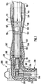
- Figures 1 and 2 show a plug 200 disposed at one end of a cable 100.
- the cable end has been stripped in a manner known per se.
- FIG. 1 shows a plug 200 disposed at one end of a cable 100.
- the cable end has been stripped in a manner known per se.
- FIG. 1 shows a conductive core 101, an insulating layer 102, a conductive screen 103 and an insulating outer sheath 104.
- a conductive plate 105 is interposed between the conductive screen 103 and the outer sheath 104. It is held by collars 107.108 enclosing the outer sheath 104.
- a grounding braid 106 is connected to the conductive plate 105.
- a ring of sealant 111 covers one end of the sheath outdoor 104.
- the socket 200 comprises in a manner known per se a multilayer sleeve 201 whose longitudinal section has, in this example, an L-shaped square, this sleeve having an axis 202 and comprising, as observed radially, an inner conductive layer 203, an insulating intermediate layer 204 and an outer conductive layer 205.
- the inner and outer layers could, as a variant, have other electrical characteristics capable of guiding an electric field, such as a semiconductor characteristic.
- the insulating layer 204 is flush with an interior surface 206 of the sleeve.
- the outer conductive layer 205 is flush with the inner surface 206 at the end of the sleeve receiving the cable, which for this purpose has a conical shape.
- the outer layer On the side of the end of the sleeve 201 receiving the cable 100, the outer layer has a cylindrical extension 210, which extends along the axis 201 of the sleeve over a length equal, in this example, to approximately half that of the sleeve 201.
- the sleeve 201 is made of an elastomeric material having a degree of elasticity allowing, after expansion and retraction of the sleeve, its adaptation to cables of substantially different diameters, more precisely cables whose diameter varies from simple to double.
- a particularly suitable elastomer is EPDM.
- the conical end 207 of the sleeve and its cylindrical extension 210 have, at rest, and at any point along the axis 202 of the sleeve, an inside diameter slightly less than the outside diameter which the end of the cable has at this point. with the smallest diameter, chosen from a series of cables of different dimensions, which we want to be able to adapt to the 200 socket. inside diameter of the conical end 207 and of the cylindrical extension 210 will also be chosen so that these parts exert, after their expansion then their retraction, a clamping force on said cable of smaller diameter.
- a socket 212 is crimped onto the conductive core 101 of the cable 100, a male contact pad 211 being fixed by screwing to a free end of the socket 212.
- the conical end 207 of the sleeve 201 and its cylindrical extension 210 are expanded radially to an inside diameter greater than the outside diameter of a corresponding part of the cable to be covered.
- the conical end 207 of the sleeve 201 and its cylindrical extension 210 have been expanded in the factory by means known in themselves, for example by using a vacuum chamber or a mandrel, and a tube 300 was introduced inside them to keep them expanding.
- the tube 300 consists of a tearable tape and comprises a cylindrical portion of small diameter 302, extended by a conical portion 303 widening towards a cylindrical portion of large diameter 304, the first cited portion covering a region of the cable in which appears its insulating layer 102, and the two other cited portions covering the cable earthing means and the putty 111.
- a ring 305 is arranged at a free end of the cylindrical portion of small diameter 302 of the tube 300 to facilitate the subsequent withdrawal of the latter.
- the conical end 207 of the sleeve 201 of the socket is supported on the small diameter cylindrical portion 302 of the tube 300 while its cylindrical extension 210 is supported on the conical portion 303 and the portion cylindrical large diameter 304.
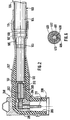
- the cable end is prepared so as to be stripped and equipped on the one hand with its socket 212, on the other hand with its earthing means 105 to 108, 111 then it is inserted inside the socket 200.
- the male contact pad 211 is then aimed at the free end of the socket 212.
- the tube 300 is gradually withdrawn by an operator, from its end arranged on more inside the socket, by tearing the ribbon.
- the conical end 207 and the cylindrical extension 210 of the sleeve 201 then retract by elasticity on the corresponding parts of the cable 100. The situation obtained is illustrated in FIG. 2.
- cylindrical extension 210 covers the means for earthing the cable in the manner of a conventional earth cover, constituted by a tubular sheath with dimensional recovery, independent of the socket.
- the socket 200 does not have a cylindrical extension 210, the latter being replaced by a conventional earth cover disposed on the cable before retraction of the socket.
- the conical end 207 of the sleeve covers the earth cover over a short length.
- the conical end 207 of the sleeve 201 and its cylindrical extension 210 carry, on an external surface, traction lugs allowing their radial expansion by means of a device ensuring traction on these traction lugs, radially outwards from the catch.
- the conductive outer layer 205 and its cylindrical extension 210 have a heat-shrinkable characteristic while the rest of the sleeve has a non-heat-shrinkable characteristic.
- the mounting of such a socket on the cable 100 comprises a first phase in which the conical end 207 of the sleeve 201 and its cylindrical extension 210 are heated and then expanded radially in the factory by means known in themselves, for example by use vacuum chamber or mandrel, then they are cooled and keep expanding.
- the conical end 207 of the sleeve 201 and its cylindrical extension 210 are heated, so that they retract on the cable 100.
- junction body 400 intended to connect the ends of two cables 501, 502, these being of identical design to that 100 of FIGS. 1 and 2.
- the junction body 400 consists of a multilayer sleeve comprising, as observed radially, an inner conductive layer 401, an insulating intermediate layer 402 and an outer conductive layer 403. Similarly to the multilayer sleeve 201 of FIGS. 1 and 2 , the insulating intermediate layer 402 is flush with an inner surface of the junction body, and the conductive outer layer has a cylindrical extension 404 at two ends, which extends over approximately 40% of the length of the junction body.
- the junction body has two conical ends 405, 406 ( Figure 5).
- the conical ends 405, 406 and the cylindrical extensions 404 of the junction body are in a state of radial expansion, while a central region of the junction body lying between the two conical ends is not not expanded.
- the junction body 400 is maintained in mechanical expansion, by means of two tubes 601, 602 constituted by a tearable tape.
- Each tube comprises a portion in truncated cone 603 extended, on one side of larger diameter, by a cylindrical portion 604, the frusto-conical portion 603 supporting a conical end 406 of the junction body 400 and the cylindrical portion 604 supporting the cylindrical extension 404 thereof.
- a cylindrical sheath 408 has a longitudinal slot 409 and, at two ends, two flanges 410 projecting radially inwards. It comprises, on an outer surface and in an axially median region, an annular bead 411 in which an annular groove 412 is formed.
- This sheath is conductive and is made of an elastic material such as EPDM.
- the sheath 408 is arranged to intimately cover a crimped socket 413 joining the two cables 501, 502, the two flanges 410 of the sheath facing two ends of the crimped socket. It extends axially from an insulating layer 503 of a cable to an insulating layer 504 of the second cable.
- the inner layer 401 of the junction body 400 carries, on an inner face and in an axially median region, an annular bead 414 whose dimensions are adapted so that it is received in the annular groove 412 of the sleeve 408.
- the sleeve 408 has several functions. On the one hand, it adapts the internal diameter of the junction body 400 to the external diameter of the crimped socket 413. On the other hand, being in contact with these two parts, it connects them electrically and allows the evacuation of heat, from the crimped socket 413 up to the junction body 400.
- junction body 400 comprises a portion having a heat-shrinkable characteristic and is therefore maintained in the expanded state without having to use support tubes.
- the unexpanded central region of the junction body of FIGS. 3 and 4 has an internal diameter greater than the largest diameter of the bulkiest cable which it is desired to be able to adapt to this junction body, so that the latter can, in all cases, be threaded onto one of the cables 501, 502 before the assembly thereof.
- the assembly between the cores of these is carried out by means of the crimped socket 413.
- the sleeve 408 is attached to the crimped socket 413 after having been enlarged, taking advantage of its elasticity.
- the junction body is brought back on the sleeve 408 and its retraction is caused.
- FIG. 5 This situation is illustrated in which the conical ends 405, 406 of the junction body are supported on the insulating layer 503, 504 of the cables, and its cylindrical extensions 404 are supported on conductive screens and insulating outer sheaths Cables.
- cylindrical extension of the conductive outer layer of the plug or of the junction body to extend over a length greater than 20% of that of these.
Landscapes
- Cable Accessories (AREA)
- Connector Housings Or Holding Contact Members (AREA)
- Multi-Conductor Connections (AREA)
Claims (12)
- Verbinder (200) zum Anbringen an einen Endbereich eines elektrischen Kabels (100) oder zur Verbindung zweier Endbereiche elektrischer Kabel, der eine mehrschichtige, zusammenhängende und eine Achse (202) aufweisende Umhüllung hat, die aufweist eine isolierende Zwischenschicht (204), welche radial zwischen zwei Schichten, die ein elektrisches Feld leiten können, angeordnet ist, nämlich einer inneren (203) und einer äußeren (205), wobei diese Umhüllung einen axial im mittleren Bereich gelegenen Abschnitt hat, der elektrische Kontaktmittel (211, 212) aufnimmt, die mit einem Leiter des mindestens einen Kabels zusammenwirken, einen ersten Endbereich (207; 405), der für ein Zusammenwirken mit einem isolierten Endbereich des Kabels bestimmt ist und einen zweiten Endbereich (406), der bestimmt ist für ein Zusammenwirken mit entweder einem anderen Verbinderteil oder mit einem isolierten Endbereich eines anderen Kabels, dadurch gekennzeichnet, daß der mindestens eine Endbereich (207; 405, 406) der Umhüllung, der für das Zusammenwirken mit einem Endbereich des Kabels bestimmt ist, sich so in einem radialen Ausdehnungszustand befindet, daß er auf jedem Punkt entlang der Achse (202) der Umhüllung einen Innendurchmesser hat, der größer ist als der Außendurchmesser, den der Endbereich des entsprechenden Kabels an diesem Punkt aufweist und der kleiner ist als dieser Außendurchmesser, wenn ein Schrumpfen des mindestens einen Endbereichs der Umhüllung ausgelöst worden ist, wohingegen der axial im mittleren Bereich befindliche Abschnitt der Umhüllung und, sofern dies der Fall ist, der Endbereich (208) der Umhüllung, der mit einem anderen Verbinderteil zusammenwirken soll, sich im radial nicht-expandierten Zustand befinden.
- Verbinder nach Anspruch 1, bei dem der mindestens eine expandierte Endbereich (207; 405, 406) der Umhüllung einen Abschnitt aus einem wärmeschrumpfbaren Material aufweist, während der Rest der Umhüllung aus einem nicht wärmeschrumpffähigen Material ist.
- Verbinder nach Anspruch 1, bei dem der mindestens eine expandierte Endbereich (207; 405, 406) der Umhüllung aus einem elastischen Material ist.
- Verbinder nach Anspruch 3, bei dem der mindestens eine expandierte Endbereich (207; 405, 406) der Umhüllung auf einer Außenfläche Ziehvorsprünge aufweist und der Verbinder Expansionsmittel hat, die mit diesen Ziehvorsprüngen zusammenwirken, um auf diese eine radial nach außen gerichtete Zugkraft auszuüben.
- Verbinder nach Anspruch 3, der im Inneren jedes der expandierten Endbereiche der Umhüllung ein Rohr (300) aufweist, das von einem abreißbaren Band gebildet ist, auf dem sich der expandierte Endbereich abstützt.
- Verbinder (200) zum Anbringen an einen Endbereich eines elektrischen Kabels (100) oder zur Verbindung zweier Endbereiche elektrischer Kabel, der eine mehrschichtige, zusammenhängende und eine Achse (202) aufweisende Umhüllung hat, die aufweist eine isolierende Zwischenschicht (204), welche radial zwischen zwei Schichten, die ein elektrisches Feld leiten können, angeordnet ist, nämlich einer inneren (203) und einer äußeren (205), wobei diese Umhüllung einen axial im mittleren Bereich gelegenen Abschnitt hat, der elektrische Kontaktmittel (211, 212) aufnimmt, die mit einem Leiter des mindestens einen Kabels zusammenwirken, einen ersten Endbereich (207; 405), der für ein Zusammenwirken mit einem isolierten Endbereich des Kabels bestimmt ist und einen zweiten Endbereich (406), der bestimmt ist für ein Zusammenwirken mit entweder einem anderen Verbinderteil oder mit einem isolierten Endbereich eines anderen Kabels, dadurch gekennzeichnet, daß der mindestens eine Endbereich (207; 405, 406) der Umhüllung, der für das Zusammenwirken mit einem Endbereich des Kabels bestimmt ist, Spreizmittel aufweist, die sie in einem radial expandierten Zustand halten, wohingegen der axial im mittleren Bereich befindliche Abschnitt der Umhüllung und, sofern dies der Fall ist, der Endbereich (208) der Umhüllung, der mit einem anderen Verbinderteil zusammenwirken soll, sich im radial nicht-expandierten Zustand befinden.
- Verbinder nach Anspruch 6, dadurch gekennzeichnet, daß die Spreizmittel, aus denen der mindestens eine expandierbare Endbereich (207; 405, 406) der Umhüllung besteht, einen Abschnitt aus einem wärmeschrumpfbaren Material aufweisen, während der Rest der Umhüllung aus einem nicht wärmeschrumpffähigen Material ist.
- Verbinder nach Anspruch 6, bei dem die Spreizmittel Vorsprünge aufweisen, die an einer Außenfläche jedes der expandierbaren Endbereiche (207; 405, 406) der Umhüllung vorgesehen sind.
- Verbinder nach einem der Ansprüche 6 bis 8, bei dem der Endbereich (207) oder die Endbereiche (405, 406) der Umhüllung mit einem Endbereich des Kabels zusammenwirken und bei dem sich die äußere Schicht (205) axial bis hin zur isolierenden Lage (204) in einer zylindrischer Verlängerung (210) dergestalt erstreckt, daß die Verlängerung einen abisolierten Teil der Abschirmung (103) und einen Mantel des Kabels aufnehmen kann.
- Verfahren zum Anbringen eines Verbinders (200) an einem Endbereich eines elektrischen Kabels (100) oder zwischen zwei Endbereichen zweier elektrischer Kabel (501, 502), wobei jedes Kabel einen Leiter (101), eine Isolierschicht (102), die den Leiter abdeckt, eine Abschirmung (103), die die Isolierschicht überdeckt und einen Mantel (104), der die Abschirmung (103) überdeckt, aufweist und der Verbinder eine mehrschichtige, zusammenhängende und eine Achse (202) aufweisende Umhüllung hat, die aufweist eine isolierende Zwischenschicht (204), welche radial zwischen zwei Schichten, die ein elektrisches Feld leiten können, angeordnet ist, nämlich einer inneren (203) und einer äußeren (205), wobei diese Umhüllung einen axial im mittleren Bereich gelegenen Abschnitt hat, der elektrische Kontaktmittel (211, 212) aufnimmt, die mit einem Leiter des mindestens einen Kabels zusammenwirken, einen ersten Endbereich (207; 405), der für ein Zusammenwirken mit einem isolierten Endbereich des Kabels bestimmt ist und einen zweiten Endbereich (406), der bestimmt ist für ein Zusammenwirken mit entweder einem anderen Verbinderteil oder mit einem isolierten Endbereich eines anderen Kabels, wobei der mindestens eine Endbereich (207; 405, 406) der Umhüllung, der für das Zusammenwirken mit einem Endbereich des Kabels bestimmt ist, in einen radialen Ausdehnungszustand gebracht werden kann, und der axial im mittleren Bereich befindliche Abschnitt der Umhüllung und, sofern dies der Fall ist, der Endbereich (208) der Umhüllung, der mit einem anderen Verbinderteil zusammenwirken soll, sich im radial nichtexpandierten Zustand befinden, gekennzeichnet durch die folgenden Schritte:- Radiales Expandieren des mindestens einen expandierbaren Endbereichs (207; 405, 406) der Umhüllung in einem Maße, daß dieser auf allen Punkten entlang der Achse (202) der Umhüllung einen Innendurchmesser aufweist, der größer ist als der Außendurchmesser, den der Endbereich des entsprechenden Kabels an diesem Punkt aufweist, wobei der axial im mittleren Bereich befindliche Abschnitt der Umhüllung und, falls der Fall vorliegt, der Endbereich (208) der Umhüllung, der für ein Zusammenwirken mit einem anderen Verbinder bestimmt ist, in einem nicht radial expandierten Zustand gehalten werden;- Einfädeln des mindestens einen Endbereichs des Kabels in den Innenraum des Verbinders, der expandiert ist, und elektrisches Verbinden des Leiters (101) des mindestens einen Kabels mit den elektrischen Kontaktmiteln (211) und- Auslösen eines Schrumpfens des mindestens einen expandierten Endbereichs (207; 405, 406) der Umhüllung über dem mindestens einen Endbereich des Kabels.
- Verfahren nach Anspruch 10, wobei die Umhüllung (201) aus einem elastischen Material gefertigt ist und nach Expandieren des mindestens einen Endbereichs (207; 405, 406) des Verbinders, der für ein Zusammenwirken mit mindestens einem Endbereich des Kabels bestimmt ist, in den Innenraum eines jeden ein Rohr (300) eingefügt wird, das einen größeren Innendurchmesser als der Außendurchmesser des Endbereichs des entsprechenden Kabels aufweist und geeignet ist, den mindestens einen Endbereich (207) der Umhüllung im expandierten Zustand zu halten und, nachdem der Endbereich des Kabels in das Innere des entsprechenden Rohrs (300) eingefügt ist, dieses entnommen wird.
- Verfahren nach Anspruch 10, bei dem der mindestens eine Endbereich (207; 405, 406) der Umhüllung, der für ein Zusammenwirken mit mindestens einem Endbereich des Kabels bestimmt ist, einen Abschnitt aus einem wärmeschrumpfbaren Material aufweist, gekennzeichnet durch die folgenden Verfahrensschritte:- Heizen des mindestens einen Endbereichs (207) der Umhüllung, der mit dem mindestens einen Endbereichs des Kabels zusammenwirken soll,- radiales Expandieren dieses mindestens einen Endbereichs (207), bis der Innendurchmesser größer ist als der Außendurchmesser des Endbereichs des entsprechenden Kabels- Abkühlen des mindestens einen Endbereichs, um ihn im expandierten Zustand zu halten,- Einbringen des mindestens einen Endbereichs des Kabels in den Innenraum des so expandierten Verbinders und elektrischer Anschluß des Leiters (101) des mindestens einen Kabels an die elektrischen Kontaktmittel (211) und- Heizen des mindestens einen Endbereichs der expandierten Umhüllung (207), um die Schrumpfung auf den mindestens einen Endbereich des Kabels zu bewirken.
Applications Claiming Priority (2)
| Application Number | Priority Date | Filing Date | Title |
|---|---|---|---|
| FR9102949A FR2674073B1 (fr) | 1991-03-12 | 1991-03-12 | Dispositif de raccordement pour un ou deux cables electriques, et procede pour monter ce dispositif a l'extremite du ou des cables |
| FR9102949 | 1991-03-12 |
Publications (3)
| Publication Number | Publication Date |
|---|---|
| EP0504035A2 EP0504035A2 (de) | 1992-09-16 |
| EP0504035A3 EP0504035A3 (en) | 1992-12-16 |
| EP0504035B1 true EP0504035B1 (de) | 1996-01-03 |
Family
ID=9410619
Family Applications (1)
| Application Number | Title | Priority Date | Filing Date |
|---|---|---|---|
| EP92400613A Expired - Lifetime EP0504035B1 (de) | 1991-03-12 | 1992-03-10 | Verbindungsvorrichtung für ein oder zwei elektrische Kabel, und Verfahren zum Montieren der Vorrichtung an das Ende des oder der Kabel |
Country Status (6)
| Country | Link |
|---|---|
| US (1) | US5230640A (de) |
| EP (1) | EP0504035B1 (de) |
| BR (1) | BR9200938A (de) |
| DE (1) | DE69207238T2 (de) |
| ES (1) | ES2084299T3 (de) |
| FR (1) | FR2674073B1 (de) |
Cited By (3)
| Publication number | Priority date | Publication date | Assignee | Title |
|---|---|---|---|---|
| US5856634A (en) * | 1997-03-19 | 1999-01-05 | Raychem Corporation | Recoverable article |
| US6329600B1 (en) | 1998-12-10 | 2001-12-11 | Nexans | Screen connection for mechanico retractable products |
| EP2819250A1 (de) | 2013-06-26 | 2014-12-31 | 3M Innovative Properties Company | Kabelverbindungsvorrichtung |
Families Citing this family (69)
| Publication number | Priority date | Publication date | Assignee | Title |
|---|---|---|---|---|
| JPH08507733A (ja) * | 1993-03-16 | 1996-08-20 | ミネソタ・マイニング・アンド・マニュファクチュアリング・カンパニー | プレストレッチ式エラストマー部材 |
| US6504103B1 (en) | 1993-03-19 | 2003-01-07 | Cooper Industries, Inc. | Visual latching indicator arrangement for an electrical bushing and terminator |
| US6984791B1 (en) | 1993-03-19 | 2006-01-10 | Cooper Technologies Company | Visual latching indicator arrangement for an electrical bushing and terminator |
| US7642465B2 (en) | 1994-06-20 | 2010-01-05 | Cooper Technologies Company | Visual latching indicator arrangement for an electrical bushing and terminator |
| JP3278502B2 (ja) * | 1993-08-13 | 2002-04-30 | 住友スリーエム株式会社 | 電線接続部の被覆チューブ |
| US5651699A (en) * | 1994-03-21 | 1997-07-29 | Holliday; Randall A. | Modular connector assembly for coaxial cables |
| US5402566A (en) * | 1994-04-04 | 1995-04-04 | The Whitaker Corporation | Method and machine for attaching an electrical connector to a coaxial cable |
| HUT77729A (hu) * | 1994-04-25 | 1998-07-28 | Minnesota Mining And Manufacturing Co. | Előnyújtott rugalmas termék |
| DE4424072C1 (de) * | 1994-07-08 | 1996-01-25 | Rheydt Kabelwerk Ag | Steckendverschluß |
| DE19500804A1 (de) * | 1995-01-13 | 1996-07-18 | Minnesota Mining & Mfg | Elastisch verformbare, annähernd T-förmige Umhüllung für eine elektrische Kabelendverschlußverbindung |
| FR2741484B1 (fr) * | 1995-11-21 | 1997-12-19 | Silec Liaisons Elec | Piece de raccordement electrique |
| FR2756674B1 (fr) * | 1996-12-02 | 1999-01-08 | Telecommunications Sa | Manchon de protection pour une jonction de cables |
| US7044760B2 (en) * | 1997-07-30 | 2006-05-16 | Thomas & Betts International, Inc. | Separable electrical connector assembly |
| US5957712A (en) * | 1997-07-30 | 1999-09-28 | Thomas & Betts International, Inc. | Loadbreak connector assembly which prevents switching flashover |
| US6168447B1 (en) | 1997-07-30 | 2001-01-02 | Thomas & Betts International, Inc. | Loadbreak connector assembly which prevents switching flashover |
| US6939151B2 (en) * | 1997-07-30 | 2005-09-06 | Thomas & Betts International, Inc. | Loadbreak connector assembly which prevents switching flashover |
| DE19746313A1 (de) * | 1997-10-21 | 1999-04-22 | Abb Patent Gmbh | Kabelendverschluß oder Kabelmuffe mit geometrischer Feldsteuerung |
| DE19845776A1 (de) * | 1998-09-22 | 2000-03-23 | Siemens Ag | T-förmige Verbindungsanschlüsse für gasisolierte Mittelspannungsschaltanlagen |
| JP3532534B2 (ja) * | 2001-05-29 | 2004-05-31 | 矢崎総業株式会社 | 同軸コネクタ |
| US6796820B2 (en) * | 2002-05-16 | 2004-09-28 | Homac Mfg. Company | Electrical connector including cold shrink core and thermoplastic elastomer material and associated methods |
| US6905356B2 (en) * | 2002-05-16 | 2005-06-14 | Homac Mfg. Company | Electrical connector including thermoplastic elastomer material and associated methods |
| US6830475B2 (en) * | 2002-05-16 | 2004-12-14 | Homac Mfg. Company | Electrical connector with visual seating indicator and associated methods |
| US6790063B2 (en) | 2002-05-16 | 2004-09-14 | Homac Mfg. Company | Electrical connector including split shield monitor point and associated methods |
| US7104823B2 (en) * | 2002-05-16 | 2006-09-12 | Homac Mfg. Company | Enhanced separable connector with thermoplastic member and related methods |
| US6811418B2 (en) * | 2002-05-16 | 2004-11-02 | Homac Mfg. Company | Electrical connector with anti-flashover configuration and associated methods |
| US7104822B2 (en) * | 2002-05-16 | 2006-09-12 | Homac Mfg. Company | Electrical connector including silicone elastomeric material and associated methods |
| NL1023128C2 (nl) * | 2003-04-09 | 2004-10-18 | Lovink Enertech B V | Kabelmof. |
| US7530841B2 (en) * | 2003-09-15 | 2009-05-12 | Corning Cabelcon A/S | Coaxial angle connector |
| DE20316059U1 (de) * | 2003-10-20 | 2003-12-18 | Asm Automation Sensorik Messtechnik Gmbh | Kabeldurchführung |
| US7182647B2 (en) * | 2004-11-24 | 2007-02-27 | Cooper Technologies Company | Visible break assembly including a window to view a power connection |
| US7341468B2 (en) | 2005-07-29 | 2008-03-11 | Cooper Technologies Company | Separable loadbreak connector and system with shock absorbent fault closure stop |
| US7572133B2 (en) | 2005-11-14 | 2009-08-11 | Cooper Technologies Company | Separable loadbreak connector and system |
| ATE450914T1 (de) | 2006-05-05 | 2009-12-15 | 3M Innovative Properties Co | ROHRFÖRMIGER KABELANSCHLUß |
| BRPI0711186A2 (pt) * | 2006-05-05 | 2011-08-23 | 3M Innovative Properties Co | terminal tubular para um cabo |
| US7494355B2 (en) | 2007-02-20 | 2009-02-24 | Cooper Technologies Company | Thermoplastic interface and shield assembly for separable insulated connector system |
| US7854620B2 (en) | 2007-02-20 | 2010-12-21 | Cooper Technologies Company | Shield housing for a separable connector |
| US7950939B2 (en) | 2007-02-22 | 2011-05-31 | Cooper Technologies Company | Medium voltage separable insulated energized break connector |
| US7666012B2 (en) | 2007-03-20 | 2010-02-23 | Cooper Technologies Company | Separable loadbreak connector for making or breaking an energized connection in a power distribution network |
| US7633741B2 (en) | 2007-04-23 | 2009-12-15 | Cooper Technologies Company | Switchgear bus support system and method |
| US7568927B2 (en) | 2007-04-23 | 2009-08-04 | Cooper Technologies Company | Separable insulated connector system |
| US7661979B2 (en) | 2007-06-01 | 2010-02-16 | Cooper Technologies Company | Jacket sleeve with grippable tabs for a cable connector |
| CN101340035B (zh) * | 2007-07-02 | 2010-08-25 | 3M创新有限公司 | 适配器、具有该适配器的电缆连接器和电缆连接器组件 |
| CN101388536B (zh) * | 2007-09-11 | 2013-05-29 | 3M创新有限公司 | 连接器靴套和具有该连接器靴套的电缆连接器组件 |
| US7695291B2 (en) | 2007-10-31 | 2010-04-13 | Cooper Technologies Company | Fully insulated fuse test and ground device |
| US7670162B2 (en) | 2008-02-25 | 2010-03-02 | Cooper Technologies Company | Separable connector with interface undercut |
| US7578682B1 (en) | 2008-02-25 | 2009-08-25 | Cooper Technologies Company | Dual interface separable insulated connector with overmolded faraday cage |
| US7950940B2 (en) | 2008-02-25 | 2011-05-31 | Cooper Technologies Company | Separable connector with reduced surface contact |
| US7905735B2 (en) | 2008-02-25 | 2011-03-15 | Cooper Technologies Company | Push-then-pull operation of a separable connector system |
| US8056226B2 (en) | 2008-02-25 | 2011-11-15 | Cooper Technologies Company | Method of manufacturing a dual interface separable insulated connector with overmolded faraday cage |
| US8109776B2 (en) | 2008-02-27 | 2012-02-07 | Cooper Technologies Company | Two-material separable insulated connector |
| US7811113B2 (en) | 2008-03-12 | 2010-10-12 | Cooper Technologies Company | Electrical connector with fault closure lockout |
| US7878849B2 (en) * | 2008-04-11 | 2011-02-01 | Cooper Technologies Company | Extender for a separable insulated connector |
| US7958631B2 (en) * | 2008-04-11 | 2011-06-14 | Cooper Technologies Company | Method of using an extender for a separable insulated connector |
| US7708576B2 (en) * | 2008-08-25 | 2010-05-04 | Cooper Industries, Ltd. | Electrical connector including a ring and a ground shield |
| US20100224407A1 (en) * | 2009-03-05 | 2010-09-09 | David Charles Hughes | Observation Port or Membrane to Assist the Proper Positioning of a Cable Accessory on a Cable |
| US20100223785A1 (en) * | 2009-03-05 | 2010-09-09 | Cooper Technologies Company | Method of Using an Observation Port or membrane to Assist the Proper Positioning of a Cable Accessory on a Cable |
| WO2010127281A1 (en) * | 2009-05-01 | 2010-11-04 | 3M Innovative Properties Company | Cold-shrink separable connector |
| US7901243B1 (en) | 2010-03-30 | 2011-03-08 | Tyco Electronics Corporation | Methods and systems for forming a protected disconnectable joint assembly |
| US9219318B2 (en) | 2010-12-22 | 2015-12-22 | Prysmian S.P.A. | Jointing assemblies for electrical cables |
| USD694193S1 (en) | 2011-03-16 | 2013-11-26 | Hubbell Incorporated | Integral jacket seal |
| US9059581B2 (en) | 2011-04-28 | 2015-06-16 | Richards Manufacturing Company, A New Jersey Limited Partnership | Cold shrinkable primary joint |
| EP2710683B1 (de) * | 2011-05-20 | 2019-08-28 | 3M Innovative Properties Company | Kabelschuh mit geerdeter oberfläche und isolierter abschirmung |
| US9762046B2 (en) * | 2013-04-18 | 2017-09-12 | Richards Manufacturing Company Sales, Inc. | Sleeve for shielding electrical joint |
| US9444176B2 (en) * | 2013-06-28 | 2016-09-13 | Thomas & Betts International, Llc | Electrical connector having cold shrink component |
| CN106030912B (zh) * | 2013-12-20 | 2019-03-12 | Ppc宽带公司 | 用于微型同轴电缆连接器的射频屏蔽件 |
| DE102018116416A1 (de) * | 2018-07-06 | 2020-01-09 | Nkt Gmbh & Co. Kg | Verbindungsmuffe |
| CN111478134B (zh) * | 2020-03-13 | 2021-04-16 | 中国电子科技集团公司第二十九研究所 | 一种密封防水型集束射频电缆组件 |
| US11631971B2 (en) * | 2020-10-19 | 2023-04-18 | CCG International Holdings Limited | Cable gland for armored electrical or fiber optic cables |
| CA3153815A1 (en) | 2021-03-24 | 2022-09-24 | Richards Mfg. Co., A New Jersey Limited Partnership | Cold shrink core |
Family Cites Families (13)
| Publication number | Priority date | Publication date | Assignee | Title |
|---|---|---|---|---|
| US3541495A (en) * | 1968-08-12 | 1970-11-17 | Raychem Corp | Connector for termination of coaxial cable |
| NL141718C (de) * | 1969-04-18 | Amp Inc | ||
| US3774141A (en) * | 1971-11-24 | 1973-11-20 | Vaco Products Co | Terminal connector and insulating sleeve therefor |
| US4196308A (en) * | 1976-01-28 | 1980-04-01 | Raychem Corporation | Insulated crimp splicer |
| US4304616A (en) * | 1979-04-02 | 1981-12-08 | Raychem Corporation | Radially shrinkable sleeves |
| DE8219184U1 (de) * | 1982-07-05 | 1982-10-14 | Walter Rose Gmbh & Co Kg, 5800 Hagen | Vorrichtung zum Kuppeln zweier Koaxialkabelenden |
| GB8325402D0 (en) * | 1983-09-22 | 1983-10-26 | Raychem Gmbh | Electrical apparatus |
| US4714438A (en) * | 1985-07-19 | 1987-12-22 | Bicc Public Limited Company | Electric cable joints |
| FR2592825B1 (fr) * | 1986-01-13 | 1988-03-11 | Artema | Manchon auxiliaire de positionnement, dispositif dote d'un tel manchon et procede de positionnement correspondant |
| DE3837120A1 (de) * | 1988-11-02 | 1990-05-03 | Rheydt Kabelwerk Ag | Kabelanschluss |
| DE9002070U1 (de) * | 1989-02-24 | 1990-04-26 | Minnesota Mining & Mfg. Co., Saint Paul, Minn. | Adapter für einen elektrischen Kabelabschluß |
| IT1230364B (it) * | 1989-08-01 | 1991-10-18 | Pirelli Cavi Spa | Elemento immagazzinabile di rivestimento di giunti di cavi elettrici, applicabile a piu' cavi di differente diametro, con strato isolante che ammette deformazione residua. |
| DE3943296C2 (de) * | 1989-12-29 | 1994-08-11 | Minnesota Mining & Mfg | Muffe zum Einhüllen einer Verbindung oder eines Endes eines Elektrokabels |
-
1991
- 1991-03-12 FR FR9102949A patent/FR2674073B1/fr not_active Expired - Lifetime
-
1992
- 1992-03-09 US US07/848,015 patent/US5230640A/en not_active Expired - Lifetime
- 1992-03-10 EP EP92400613A patent/EP0504035B1/de not_active Expired - Lifetime
- 1992-03-10 DE DE69207238T patent/DE69207238T2/de not_active Expired - Lifetime
- 1992-03-10 ES ES92400613T patent/ES2084299T3/es not_active Expired - Lifetime
- 1992-03-12 BR BR929200938A patent/BR9200938A/pt not_active IP Right Cessation
Cited By (3)
| Publication number | Priority date | Publication date | Assignee | Title |
|---|---|---|---|---|
| US5856634A (en) * | 1997-03-19 | 1999-01-05 | Raychem Corporation | Recoverable article |
| US6329600B1 (en) | 1998-12-10 | 2001-12-11 | Nexans | Screen connection for mechanico retractable products |
| EP2819250A1 (de) | 2013-06-26 | 2014-12-31 | 3M Innovative Properties Company | Kabelverbindungsvorrichtung |
Also Published As
| Publication number | Publication date |
|---|---|
| FR2674073A1 (fr) | 1992-09-18 |
| EP0504035A2 (de) | 1992-09-16 |
| FR2674073B1 (fr) | 1996-05-10 |
| US5230640A (en) | 1993-07-27 |
| EP0504035A3 (en) | 1992-12-16 |
| BR9200938A (pt) | 1992-11-17 |
| DE69207238D1 (de) | 1996-02-15 |
| ES2084299T3 (es) | 1996-05-01 |
| DE69207238T2 (de) | 1996-07-18 |
Similar Documents
| Publication | Publication Date | Title |
|---|---|---|
| EP0504035B1 (de) | Verbindungsvorrichtung für ein oder zwei elektrische Kabel, und Verfahren zum Montieren der Vorrichtung an das Ende des oder der Kabel | |
| EP0974179A1 (de) | Vorrichtung zum verbinden elektrischer kabel | |
| FR2493050A1 (fr) | Connecteur pour cable coaxial | |
| CA1299688C (fr) | Dispositif de connexion autodenudant | |
| CH626754A5 (en) | Method for joining high-voltage cables and device for implementing this method | |
| FR2503476A1 (fr) | Procede de depose d'une gaine protectrice sur l'extremite d'un cable electrique et dispositif pour la mise en oeuvre de celui-ci | |
| EP1394900B1 (de) | Verbinder für zwei elecktrische Energiekabel und Verbindung mit einem solchen Verbinder | |
| EP0933856B1 (de) | Kaltschrumpfbare Dichtungsmuffe für elektrische Kabel | |
| EP0132208A1 (de) | Abspannklemme für isolierte Tragseile mit mehreren Leitern | |
| EP0549942B1 (de) | Verbindung von elektrischen Kabeln, vormontierter Verbindungszusammenbau und Herstellungsverfahren | |
| EP0862801B1 (de) | Elektrisches kupplungsteil | |
| EP0669677A1 (de) | Elektrische Verbinderanordnung für leitende Kabelabschirmung und Verfahren zu ihrer Ausführung | |
| FR2527015A1 (fr) | Connecteur verrouillable et deverrouillable pour cables electriques | |
| EP0732768B1 (de) | Verfahren zur Herstellung einer elektrischen Verbindung mit einer metallenen Abschirmung eines Energiekabels und Ring zur Durchführung des Verfahrens | |
| EP0508884B1 (de) | Verbinder für optische Faserkabel | |
| FR2825529A1 (fr) | Dispositif de maintien en expansion d'un manchon elastique | |
| FR2745960A1 (fr) | Dispositif de raccordement electrique permettant de connecter plusieurs cables de derivation a partir d'un cable d'arrivee | |
| CA2238260C (fr) | Piece de raccordement electrique | |
| EP0246974A1 (de) | Isoliermuffe für den einpoligen Endverschluss einer elektrischen Leitung | |
| EP0683556A1 (de) | Struktur einer elektrischen Verbindung einer Schutzhülse mit einem Ende einer halbleitenden Abschirmung eines elektrischen Kabels | |
| FR2709025A1 (fr) | Contact électrique élastique. | |
| FR2760146A1 (fr) | Manchon d'etancheite et de protection pour une extremite de cable electrique | |
| EP0278844A1 (de) | Elektrisches Kabel, insbesondere isoliert mit getränktem Papier, an dessen Ende eine Verbindungsvorrichtung angeordnet ist | |
| CA1296400C (fr) | Cable electrique, notamment isole au papier impregne, a l'extremite duquel est rapporte un dispositif de raccordement | |
| BE835135Q (fr) | Dispositif de connexion pour installation electrique |
Legal Events
| Date | Code | Title | Description |
|---|---|---|---|
| PUAI | Public reference made under article 153(3) epc to a published international application that has entered the european phase |
Free format text: ORIGINAL CODE: 0009012 |
|
| AK | Designated contracting states |
Kind code of ref document: A2 Designated state(s): DE ES GB IT |
|
| PUAL | Search report despatched |
Free format text: ORIGINAL CODE: 0009013 |
|
| AK | Designated contracting states |
Kind code of ref document: A3 Designated state(s): DE ES GB IT |
|
| 17P | Request for examination filed |
Effective date: 19930308 |
|
| 17Q | First examination report despatched |
Effective date: 19950307 |
|
| RAP3 | Party data changed (applicant data changed or rights of an application transferred) |
Owner name: CABLES PIRELLI |
|
| GRAA | (expected) grant |
Free format text: ORIGINAL CODE: 0009210 |
|
| AK | Designated contracting states |
Kind code of ref document: B1 Designated state(s): DE ES GB IT |
|
| REF | Corresponds to: |
Ref document number: 69207238 Country of ref document: DE Date of ref document: 19960215 |
|
| ITF | It: translation for a ep patent filed | ||
| GBT | Gb: translation of ep patent filed (gb section 77(6)(a)/1977) |
Effective date: 19960227 |
|
| REG | Reference to a national code |
Ref country code: ES Ref legal event code: FG2A Ref document number: 2084299 Country of ref document: ES Kind code of ref document: T3 |
|
| PLBE | No opposition filed within time limit |
Free format text: ORIGINAL CODE: 0009261 |
|
| STAA | Information on the status of an ep patent application or granted ep patent |
Free format text: STATUS: NO OPPOSITION FILED WITHIN TIME LIMIT |
|
| 26N | No opposition filed | ||
| REG | Reference to a national code |
Ref country code: GB Ref legal event code: IF02 |
|
| REG | Reference to a national code |
Ref country code: GB Ref legal event code: 732E |
|
| REG | Reference to a national code |
Ref country code: GB Ref legal event code: 732E |
|
| PGFP | Annual fee paid to national office [announced via postgrant information from national office to epo] |
Ref country code: DE Payment date: 20110329 Year of fee payment: 20 Ref country code: GB Payment date: 20110325 Year of fee payment: 20 Ref country code: ES Payment date: 20110328 Year of fee payment: 20 |
|
| PGFP | Annual fee paid to national office [announced via postgrant information from national office to epo] |
Ref country code: IT Payment date: 20110329 Year of fee payment: 20 |
|
| REG | Reference to a national code |
Ref country code: DE Ref legal event code: R071 Ref document number: 69207238 Country of ref document: DE |
|
| REG | Reference to a national code |
Ref country code: DE Ref legal event code: R071 Ref document number: 69207238 Country of ref document: DE |
|
| REG | Reference to a national code |
Ref country code: GB Ref legal event code: PE20 Expiry date: 20120309 |
|
| PG25 | Lapsed in a contracting state [announced via postgrant information from national office to epo] |
Ref country code: DE Free format text: LAPSE BECAUSE OF EXPIRATION OF PROTECTION Effective date: 20120311 |
|
| REG | Reference to a national code |
Ref country code: ES Ref legal event code: FD2A Effective date: 20120604 |
|
| PG25 | Lapsed in a contracting state [announced via postgrant information from national office to epo] |
Ref country code: GB Free format text: LAPSE BECAUSE OF EXPIRATION OF PROTECTION Effective date: 20120309 |
|
| PG25 | Lapsed in a contracting state [announced via postgrant information from national office to epo] |
Ref country code: ES Free format text: LAPSE BECAUSE OF EXPIRATION OF PROTECTION Effective date: 20120311 |