EP0132208A1 - Abspannklemme für isolierte Tragseile mit mehreren Leitern - Google Patents
Abspannklemme für isolierte Tragseile mit mehreren Leitern Download PDFInfo
- Publication number
- EP0132208A1 EP0132208A1 EP84420098A EP84420098A EP0132208A1 EP 0132208 A1 EP0132208 A1 EP 0132208A1 EP 84420098 A EP84420098 A EP 84420098A EP 84420098 A EP84420098 A EP 84420098A EP 0132208 A1 EP0132208 A1 EP 0132208A1
- Authority
- EP
- European Patent Office
- Prior art keywords
- conductors
- complementary
- conical
- grooves
- sleeve
- Prior art date
- Legal status (The legal status is an assumption and is not a legal conclusion. Google has not performed a legal analysis and makes no representation as to the accuracy of the status listed.)
- Ceased
Links
Images

Classifications
-
- H—ELECTRICITY
- H02—GENERATION; CONVERSION OR DISTRIBUTION OF ELECTRIC POWER
- H02G—INSTALLATION OF ELECTRIC CABLES OR LINES, OR OF COMBINED OPTICAL AND ELECTRIC CABLES OR LINES
- H02G7/00—Overhead installations of electric lines or cables
- H02G7/05—Suspension arrangements or devices for electric cables or lines
- H02G7/053—Suspension clamps and clips for electric overhead lines not suspended to a supporting wire
- H02G7/056—Dead-end clamps
Definitions
- the present invention relates to an anchoring clamp for insulated carrying cables with several conductors of overhead electrical lines.
- a type of clamp known for anchoring such lines comprises a conical core formed by two elements between which are formed four grooves each of which is capable of accommodating one of the conductors of the cable and intended to be engaged in the recess conical of a support which ensures, by wedging, the centering of the two elements of the core.
- Another type of clamp comprises a conical monobloc core comprising on two opposite faces two pairs of grooves, each of which is capable of housing one of the conductors of the cable, and intended to be engaged in a U-shaped section piece and delimiting a recess conical.
- a cylindrical core has four grooves in which the cable conductors are engaged; after being placed on these cables, this core is placed inside a conical part in which it is wedged by sliding of a conical member.
- the object of the present invention is therefore to produce a clamp of the type described above, but which can be adapted to different cable sections. while ensuring a good tightening of these.
- the central corner is first introduced into the twist of the cable and the conductors put in place in the grooves which it presents, the whole is then introduced into the intermediate sleeve, then into the body, with compression of the sleeve in this body.
- This compression is authorized by the deformation of the longitudinal groove and the bringing together of the two conical wings of the intermediate sleeve.
- the tightening is therefore carried out by the complementary slight slopes of the body and of the intermediate sleeve and thus enables significant forces to be supported.
- the clamp has a steep slope, necessary for easy adaptation of the clamp to several cable diameters, without excessively increasing the length of the corner, since a large variation in the diameter of the cable conductors corresponds to a small displacement from the neighborhood.
- the intermediate sleeve carries a breakable outer tongue, temporarily limiting its sinking in the body to allow the correct engagement of the wedge in the intermediate sleeve.
- the breakage of this tongue then authorizes the insertion of the intermediate sleeve in the body, so as to effect the jamming and tightening of the cable conductors.
- the sleeve has, in the two inner faces of the wings of the U, two pairs of complementary grooves and facing those of the central corner. These grooves cooperate with those of the central corner to ensure good maintenance of the cable conductors.
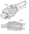
- this clamp essentially comprises a body (2) of general U-shape and delimiting a conical recess (2a) with a slight slope, a conical intermediate sleeve in the form of U (3) and a central corner ( 4), the conductors (5) of the cable being held between the central corner (4) and the sleeve (3).
- the conical intermediate sleeve (3) has, on the outside, a slight slope (3a) complementary to that of the conical recess (2a) of the body (2) and, internally, a steep slope (3b) complementary to that of the central corner (4). It also has a pair of grooves (3c) in each inner face of its wings, grooves each intended to receive a conductor (5) of the cable, an external tongue (3d) and a longitudinal internal groove (3e) formed in its bottom wall.
- the central corner (4) also conical in shape, has in its two opposite lateral faces, two pairs of grooves (4a), each of these grooves cooperating with one of the grooves (3c) of the sleeve (3) to receive a cable conductor (5).
- the central corner (4) is introduced into the twist formed by the conductors (5) of the cable, the latter being housed in the grooves (4a) provided for this purpose.
- the wedge (4) is then introduced into the intermediate sleeve (3), the opening of which allows the conductors (5) to pass.
- the whole, that is to say the assembly formed by the intermediate sleeve (3), the central corner (4) and the conductors (5), is then introduced into the body (2) [cf. fig. 4].
- the force exerted by the fitter causes the central corner-cable assembly to penetrate into the intermediate sleeve (3) and the tongue (3d), abutting against the end face of the body (2), prevents the sleeve (3) from penetrate further into the body (2) [cf. fig. 5].
- the tongue (3d) breaks under the effect of significant forces involved (the voltage of the power line is around 1000 daN)) and the intermediate sleeve (3) is driven and slides in the body (2), with its two conical wings allowed by the deformation of the longitudinal groove (3e), the central corner (4), already in place by hand, can no longer progress [cf. fig. 2].
- the four conductors (5) of the cable are held between the central corner (4) and the intermediate sleeve (3) in the grooves (4a) and (3c).
- the tightening is thus caused by the slight slopes (3a) and (2a) respectively of the intermediate sleeve (3) and of the body (2), and is not likely to be annihilated, even by significant forces acting in the opposite direction. .
- this clamp can be used for anchoring conductors (5) of very different diameters, which implies only one relatively small axial offset of the wedge (4) relative to the intermediate sleeve (3).
- the same clamp can be used for cables whose conductor cross-section varies from 25 to 50 mm 2 .
Landscapes
- Installation Of Indoor Wiring (AREA)
Applications Claiming Priority (2)
| Application Number | Priority Date | Filing Date | Title |
|---|---|---|---|
| FR8310270A FR2547682A1 (fr) | 1983-06-15 | 1983-06-15 | Pince d'ancrage pour cables porteurs isoles a plusieurs conducteurs |
| FR8310270 | 1983-06-15 |
Publications (1)
| Publication Number | Publication Date |
|---|---|
| EP0132208A1 true EP0132208A1 (de) | 1985-01-23 |
Family
ID=9290023
Family Applications (1)
| Application Number | Title | Priority Date | Filing Date |
|---|---|---|---|
| EP84420098A Ceased EP0132208A1 (de) | 1983-06-15 | 1984-06-07 | Abspannklemme für isolierte Tragseile mit mehreren Leitern |
Country Status (2)
| Country | Link |
|---|---|
| EP (1) | EP0132208A1 (de) |
| FR (1) | FR2547682A1 (de) |
Cited By (9)
| Publication number | Priority date | Publication date | Assignee | Title |
|---|---|---|---|---|
| EP0212643A2 (de) * | 1985-08-26 | 1987-03-04 | Georg Fischer Aktiengesellschaft | Seilabspannklemme |
| FR2594268A1 (fr) * | 1986-02-10 | 1987-08-14 | Lienart Jean Pierre | Pince d'ancrage pour cable cylindrique. |
| US5018251A (en) * | 1988-11-10 | 1991-05-28 | Stc Plc | Cable anchorage |
| EP0809340A1 (de) * | 1996-05-20 | 1997-11-26 | Giorgio Boscolo | Aufhängevorrichtung für Luftkanale, insbesondere Nachrichtenkabel |
| EP1255339A1 (de) * | 2001-05-05 | 2002-11-06 | Richard Bergner Elektroarmaturen GmbH & Co.KG | Schraubenlose Keilspannklemme |
| GB2407858A (en) * | 2003-11-06 | 2005-05-11 | John Doris | A cable stop |
| ITMI20081908A1 (it) * | 2008-10-29 | 2010-04-30 | Gorla Morsetterie S R L | Morsa di ammarro per corde di linee elettriche |
| CN102136708A (zh) * | 2011-01-25 | 2011-07-27 | 永固集团股份有限公司 | 平行集束型绝缘电缆耐张线夹 |
| CN102642752A (zh) * | 2012-05-07 | 2012-08-22 | 南通瑞鑫电子电器有限公司 | 随行扁电缆固定装置 |
Citations (4)
| Publication number | Priority date | Publication date | Assignee | Title |
|---|---|---|---|---|
| FR616730A (fr) * | 1926-05-27 | 1927-02-07 | Agrafes pour haubans | |
| DE687212C (de) * | 1937-03-07 | 1940-01-25 | Karl Pfisterer | Abspannklemme fuer Stahlaluminiumseile |
| BE811115A (fr) * | 1973-02-16 | 1974-05-29 | Serre-fil terminal pour cable suspendu | |
| FR2256569A1 (en) * | 1973-12-27 | 1975-07-25 | Maleyre Henri | Anchorage for low-voltage overhead cables - has wedge-shaped jaws to grip cables within the main anchorage |
-
1983
- 1983-06-15 FR FR8310270A patent/FR2547682A1/fr active Pending
-
1984
- 1984-06-07 EP EP84420098A patent/EP0132208A1/de not_active Ceased
Patent Citations (4)
| Publication number | Priority date | Publication date | Assignee | Title |
|---|---|---|---|---|
| FR616730A (fr) * | 1926-05-27 | 1927-02-07 | Agrafes pour haubans | |
| DE687212C (de) * | 1937-03-07 | 1940-01-25 | Karl Pfisterer | Abspannklemme fuer Stahlaluminiumseile |
| BE811115A (fr) * | 1973-02-16 | 1974-05-29 | Serre-fil terminal pour cable suspendu | |
| FR2256569A1 (en) * | 1973-12-27 | 1975-07-25 | Maleyre Henri | Anchorage for low-voltage overhead cables - has wedge-shaped jaws to grip cables within the main anchorage |
Cited By (12)
| Publication number | Priority date | Publication date | Assignee | Title |
|---|---|---|---|---|
| EP0212643A2 (de) * | 1985-08-26 | 1987-03-04 | Georg Fischer Aktiengesellschaft | Seilabspannklemme |
| EP0212643A3 (en) * | 1985-08-26 | 1988-01-13 | Georg Fischer Aktiengesellschaft | Cable-anchoring clamp |
| FR2594268A1 (fr) * | 1986-02-10 | 1987-08-14 | Lienart Jean Pierre | Pince d'ancrage pour cable cylindrique. |
| EP0237447A1 (de) * | 1986-02-10 | 1987-09-16 | Malico | Verankerungsklemme für ein zylindrisches Kabel |
| US5018251A (en) * | 1988-11-10 | 1991-05-28 | Stc Plc | Cable anchorage |
| EP0809340A1 (de) * | 1996-05-20 | 1997-11-26 | Giorgio Boscolo | Aufhängevorrichtung für Luftkanale, insbesondere Nachrichtenkabel |
| EP1255339A1 (de) * | 2001-05-05 | 2002-11-06 | Richard Bergner Elektroarmaturen GmbH & Co.KG | Schraubenlose Keilspannklemme |
| GB2407858A (en) * | 2003-11-06 | 2005-05-11 | John Doris | A cable stop |
| ITMI20081908A1 (it) * | 2008-10-29 | 2010-04-30 | Gorla Morsetterie S R L | Morsa di ammarro per corde di linee elettriche |
| CN102136708A (zh) * | 2011-01-25 | 2011-07-27 | 永固集团股份有限公司 | 平行集束型绝缘电缆耐张线夹 |
| CN102136708B (zh) * | 2011-01-25 | 2012-11-21 | 永固集团股份有限公司 | 平行集束型绝缘电缆耐张线夹 |
| CN102642752A (zh) * | 2012-05-07 | 2012-08-22 | 南通瑞鑫电子电器有限公司 | 随行扁电缆固定装置 |
Also Published As
| Publication number | Publication date |
|---|---|
| FR2547682A1 (fr) | 1984-12-21 |
Similar Documents
| Publication | Publication Date | Title |
|---|---|---|
| EP0504035B1 (de) | Verbindungsvorrichtung für ein oder zwei elektrische Kabel, und Verfahren zum Montieren der Vorrichtung an das Ende des oder der Kabel | |
| EP0854547A1 (de) | Elektrisches koaxiales Steckerelement mit beweglichem Kontakt und elektrischer Koaxialstecker mit einem solchen Steckerelement | |
| EP1107378A1 (de) | Kontaktorgan für einen elektrischen Steckverbinder | |
| FR2865319A1 (fr) | Dispositif de connexion et manchon de contact | |
| EP0132208A1 (de) | Abspannklemme für isolierte Tragseile mit mehreren Leitern | |
| EP1469560A1 (de) | Kontaktteil für einen elektrischen Verbinder | |
| FR2782194A1 (fr) | Dispositif de connexion auto-denudant | |
| FR2716243A1 (fr) | Insert destiné à être rapport et fixé au travers d'un élément. | |
| FR2673331A1 (fr) | Dispositif pour obturer une cavite de contact d'un connecteur electrique ou optique. | |
| CA2434592A1 (fr) | Dispositif de liaison entre un cable et un element de contact | |
| FR2473799A1 (de) | ||
| FR2783099A1 (fr) | Ensemble de connexion hermetique | |
| FR2527015A1 (fr) | Connecteur verrouillable et deverrouillable pour cables electriques | |
| FR2476920A1 (fr) | Prise de terre a foncage direct perfectionnee | |
| WO1996033524A1 (fr) | Dispositif de raccord arriere pour connecteur electrique pour cable blinde | |
| EP0013655B1 (de) | Verankerungshülse für einen blanken elektrischen Leiter und Deformiervorrichtung zur Gewährleistung ihrer Verbindung mit einem blanken elektrischen Leiter durch Ziehen | |
| FR2697671A1 (fr) | Lampe à décharge du type à enveloppe tubulaire avec culot métallique, et cosse de raccord pour une telle lampe à décharge. | |
| WO1997019495A1 (fr) | Piece de raccordement electrique | |
| EP0136242A1 (de) | Verankerungsklemme für ein isoliertes elektrisches Kabel | |
| FR2718294A1 (fr) | Elément de connecteur coaxial pour câble électrique coaxial, et son procédé de montage. | |
| FR2596588A1 (fr) | Contact femelle a douille fendue pour connecteur electrique | |
| FR3121852A1 (fr) | Outil pour produire un agencement, procédé pour produire l'agencement avec l'outil et agencement | |
| EP1612890A1 (de) | Verbindungsteil für ein elektrisches Kabel, insbesondere für Mittelspannung | |
| WO2000062373A1 (fr) | Dispositif de connexion pour fil electrique comportant une fente de denudage et de retenue | |
| EP0345189A1 (de) | Elektrischer Steckverbinder |
Legal Events
| Date | Code | Title | Description |
|---|---|---|---|
| PUAI | Public reference made under article 153(3) epc to a published international application that has entered the european phase |
Free format text: ORIGINAL CODE: 0009012 |
|
| AK | Designated contracting states |
Designated state(s): AT BE CH DE GB IT LI LU NL SE |
|
| 17P | Request for examination filed |
Effective date: 19841122 |
|
| STAA | Information on the status of an ep patent application or granted ep patent |
Free format text: STATUS: THE APPLICATION HAS BEEN REFUSED |
|
| 18R | Application refused |
Effective date: 19870521 |
|
| RIN1 | Information on inventor provided before grant (corrected) |
Inventor name: LIENART, JEAN-PIERRE FERNAND |