EP0503085A1 - Magnetische abschirmungsstruktur - Google Patents
Magnetische abschirmungsstruktur Download PDFInfo
- Publication number
- EP0503085A1 EP0503085A1 EP91916939A EP91916939A EP0503085A1 EP 0503085 A1 EP0503085 A1 EP 0503085A1 EP 91916939 A EP91916939 A EP 91916939A EP 91916939 A EP91916939 A EP 91916939A EP 0503085 A1 EP0503085 A1 EP 0503085A1
- Authority
- EP
- European Patent Office
- Prior art keywords
- high permeability
- magnetic field
- cylindrical
- cylinder
- collar
- Prior art date
- Legal status (The legal status is an assumption and is not a legal conclusion. Google has not performed a legal analysis and makes no representation as to the accuracy of the status listed.)
- Granted
Links
Images



Classifications
-
- H—ELECTRICITY
- H05—ELECTRIC TECHNIQUES NOT OTHERWISE PROVIDED FOR
- H05K—PRINTED CIRCUITS; CASINGS OR CONSTRUCTIONAL DETAILS OF ELECTRIC APPARATUS; MANUFACTURE OF ASSEMBLAGES OF ELECTRICAL COMPONENTS
- H05K9/00—Screening of apparatus or components against electric or magnetic fields
- H05K9/0073—Shielding materials
- H05K9/0075—Magnetic shielding materials
- H05K9/0077—Magnetic shielding materials comprising superconductors
-
- G—PHYSICS
- G01—MEASURING; TESTING
- G01R—MEASURING ELECTRIC VARIABLES; MEASURING MAGNETIC VARIABLES
- G01R33/00—Arrangements or instruments for measuring magnetic variables
- G01R33/20—Arrangements or instruments for measuring magnetic variables involving magnetic resonance
- G01R33/28—Details of apparatus provided for in groups G01R33/44 - G01R33/64
- G01R33/42—Screening
- G01R33/421—Screening of main or gradient magnetic field
-
- Y—GENERAL TAGGING OF NEW TECHNOLOGICAL DEVELOPMENTS; GENERAL TAGGING OF CROSS-SECTIONAL TECHNOLOGIES SPANNING OVER SEVERAL SECTIONS OF THE IPC; TECHNICAL SUBJECTS COVERED BY FORMER USPC CROSS-REFERENCE ART COLLECTIONS [XRACs] AND DIGESTS
- Y10—TECHNICAL SUBJECTS COVERED BY FORMER USPC
- Y10S—TECHNICAL SUBJECTS COVERED BY FORMER USPC CROSS-REFERENCE ART COLLECTIONS [XRACs] AND DIGESTS
- Y10S505/00—Superconductor technology: apparatus, material, process
- Y10S505/825—Apparatus per se, device per se, or process of making or operating same
- Y10S505/872—Magnetic field shield
Definitions
- the present invention relates to a magnetically shielding structure utilizing a superconductor cylinder and, in particular, it relates to a magnetically shielding structure in which magnetically shielding capability is made to improved by combining magnetically shielding materials of various different properties and a penetrating magnetic field from the opening portion of the superconductor cylinder is reduced to a very small value, the volume of a usable highly magnetically shielded space inside the cylinder bore is increased, or a very feeble magnetic field can be realized in the cylinder bore even in the case of a short superconductor cylinder, thereby a much feebler magnetic field than an external one can be effectively realized in the cylinder bore.
- Meissner effect is utilized for the magnetic shield. That is, a material having Meissner effect is, for example, formed into a cylinder shape to form a shielding body and it is cooled below the critical temperature Tc for the transition to a superconductive state for making the shielding body a diamagnetic thereby a magnetic flux is forced out to the exterior of the shielding body, and the internal space of the shielding body is magnetically shielded.
- the shielding capability for longitudinal magnetic field is not enough in comparison with that for lateral magnetic field, and because of the limited value of permeability, the shielding efficiency of a single-layer cylinder can not be high enough, so that, for obtaining high shielding capability, a plurality of cylinder walls have to be laminated and a structure in which the inner layer is shorter than the outer layer has to be adopted.
- the present invention is invented considering various aspects as described in the above, and the object of the invention is to provide a magnetically shielding structure in which the shielding capability is improved by combining magnetically shielding materials of various different properties, a volume of a high-degree usable magnetically shielded space is increased by suppressing a penetrating magnetic field through the opening portion of a superconductor cylinder to be at a low value, or an extremely feeble magnetic field can be realized in a specified space in the cylinder even in the case of a short superconductor cylinder, thereby an extremely feeble magnetic field can be efficiently realized in comparison with an external magnetic field.
- an magnetically shielding structure against a penetrting magnetic field which shows an attenuating distribution toward the center on the longitudinal axis of a cylindrical shielding body composed of a material manifesting Meissner effect, a wide variety of combinations of the cylindrical magnetic shielding body composed of a superconductive material which manifests Meissner effect and a cylindrical collar means made of a high permeability material having a through opening along the longitudinal direction of the cylindrical magnetic shielding body is disposed for absorbimg and magnetically shorteing the penetrating magnetic field by the magnetic induction generated in the high permeability material.
- Fig. 20 shows a schematic diagram of a penetrating magnetic vector inside a superconductor cylinder when a lateral magnetic field is applied to the superconductor cylinder.
- a penetrating magnetic field being thus distributed is attenuated to decrease the penetration quantity coming into the inside of the superconductor cylinder by utilizing a property of a high permeability member called magnetic induction which magnetically shorts the penetrating magnetic field. Since a high permeability member may have a residual magnetic field, it has to be disposed in a position where the residual magnetic field does not exert its magnetic influence on the objective space of a feeble magnetic field.
- Fig. 1 is an illustrative representation showing the constitution of an ordinary embodiment of the present invention.
- an end portion of a cylindrical shielding body (1) composed of an oxide superconductive material.
- the length of the shielding body (1) is generally required in a range of 2 times to 20 times the sectional diameter of the cylinder. The range, however, can be changed according to the size of a shielded space or to the intensity of a magnetic field inside the space.
- a sectional view is shown in which a large diameter ferromagnetic cylindrical collar (2) and a small diameter ferromagnetic cylinderical collar(3) are disposed in the opening portion of the cylindrical magnetically shielding body (1) in a coaxial manner for the prevention of magnetic penetration.
- FIG. 1 there are shown a space G1 and a distance d1 between the magnetically shielding body (1) and the large diameter ferromagnetic cylindrical collare (2), a space G2, and a distance d2, between the large diameter ferromagnetic cylindrical collar (2) and the small diameter ferromagnetic cylindrical collar (3), and an internal space G3 of the small diameter ferromagnetic cylindrical collar (3) and a distance d3 from the wall of the small diameter cylindrical collar (3) to the center axis.
- a part denoted with the numeral (4) is a magnetic field sensor placed in an objective feeble magnetic field space.
- Equation (I) expresses the magnetic field intensity Ht when an external magnetic field is applied to the cylinder in the direction perpendicular to the cylinder axis (lateral magnetic field), and Equation (II) expresses the magnetic field intensity Ha when an external magnetic field is applied to the cylinder in the direction parallel to the cylinder axis (longitudinal magnetic field).
- R1 is the radius of the superconductor cylinder and Z is the distance from the opening end of the cylinder.
- cylindrical collar means made of a high permeability material is disposed in the position within the range from the center portion to the end portion of the superconductor cylinder or disposed in the vicinity of the end portion of the cylinder body, a mode in which a plurality of cylindrical collar means of a high permeability material are arranged in the longitudinal direction in the vicinity of the end portion, a mode in which a plurality of cylindrical collar means of a high permeability material are disposed in multiple coaxial manner in the radial direction, etc.
- a magnetic field penetrating into the cylindrical superconductor shielding body can be decreased better than in the case where the single/collar of a high permeability material is used.
- the cylindrical collar of a high permeability material of any shape can be used, so far as the collar can be inserted into the cylindrical shielding body of a superconductive material, and magnetic induction can be generated in the collar of a high permeability material and the penetrating magnetic field is absorbed in the high permeability material and is magnetically shorted.
- the coller is, to be in concrete, of a double open end type having a long cylinder length in comparison with the thickness, and their shapes can be a circle, an ellipse or a polygon.
- the collar can also be formed as a tapered cylindrical collar in which the inner diameter decreases with the increase in the distance from an end portion in the longitudinal direction or a cylindrical collar in which the shape of an inner cross section differs from that of an outer cross section having uneven places on the outer or inner surface.
- the shielding cylindre body can be formed as a cylindrical body in which the inner portion has a larger diameter in comparison with that of the end portion, a bellows-shaped cylindrical body, a cylinder of an L type, a T type, an H type, a cross type, a U type, or their combinations.
- the ratio of the outer diameter of the collar of the high permeability material to the inner diameter a cylindrical shielding body composed of the superconductive material is, as shown in embodiments to be described later, when the collar of the high permeability material is used as a single piece and the collar having the outer diameter of more than 1/5 the inner diameter of the cylindrical shielding body is disposed inside the superconductor cylinder body, a better shielding effect can be obtained than that when a superconductor cylinder is used alone.
- a method for calculating the attenuating quantity of a magnetic field penetrating through the gap betweenthe superconductive body and the ferromagnetic collar is elucidated and the present invention is based on the result.
- Fig. 2 is a diagram showing the calculation result of an attenuating quantity of a magnetic field penetrating through the gap between the superconductor body and the ferromagnetic collar.
- the ordinate shows the K value of the exponent "exp(-Kz/d) or K' value of "10 -K'Z/d "
- the abscissa shows a relative diameter D of an inner cylindrical member assuming that the diameter of an outer cylindrical member is 1, or the gap g between the inner and the outer cylindrical member.
- MSt denotes a magnetic field attenuation constant in the gap between cylindrical menbers for an external magnetic field (t) perpendicular to the cylinder axes of inside cylindrical ferromagnetic member (M) and the outside cylindrical superconductive member (S)
- SMa denotes a magnetic field attenuation constant in the gap between both cylindrical members for an external magnetic field (a) in the direction of the axes of the inside cylindrical superconductive member (S) and the outside cylindrical ferromagnetic member (M).
- n is increased, the attenuation quantity of a magnetic field can be made large, there is, however, a limit because of the distances between them.
- the clearance between the superconductive member and the ferromagnetic member is, in particular, limited because cooling is needed for the superconductive member.
- the internal magnetic field Hi 2 ⁇ r ⁇ t ⁇ Ho/ ⁇ (III) where ⁇ is permeability, t a thickness and r a radius, thus the attenuation quantity of a magnetic field has a finite value.
- ⁇ permeability, t a thickness and r a radius
- the practical limit of attenuation is in the order of 10 ⁇ 5 .
- the value of n is decided in consideration of these points.
- a penetrating magnetic field which shows an attenuating distribution toward the center on the longitudinal axis of a cylindrical shielding body being composed of a material manifesting Meissner effect
- magnetic induction is generated in a cylindrical collar means of a high permeability material, and in the result, a penetrating magnetic field is absorbed in the high permeability material and is magnetically shorted resulting in further decrease in the magnetic field penetrating into the inside of the cylindrical shielding body of the superconductive material.
- shielding structures in which a cylindrical collar means of a high permeability material is disposed inside a superconductor cylinder body or disposed in the vicinity of the end portion of the body, a plurality of cylindrical collars of the high permeability material are arranged in the longitudinal direction in the vicinity of the end portion, or a plurality of cylindrical collars of the high permeability material are arranged in a coaxial manner in the radial direction.
- the shielding structures in which a plurality of cylindrical collars of a high permeability material are arranged in the radial direction and/or longitudinal direction leaving spaces and/or intervals in multiple layer and/or in lamination can better decrease a magnetic field penetrating into the inside of a cylindrical superconductor shielding body than those in which a single collar of high permeabilitycylinder is used.
- a shielding effect can be obtained which is not possible to obtain with a shielding cylinder body alone, a volume of a usable space of a feeble magnetic field intensity can be increased, and the length of the cylindrical superconductor shielding body for obtaining an objective magnetically shielded space or a space of feeble magnetic field intensity can be shortened, which makes it possible to decrease the cost of a shielding equipment.
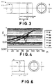
- Fig. 3 is a schematic sectional view in which collars of a high permeability material are disposed having an outer diameter D, which is selected, and the high permeability collar FM is disposed on each side in a position at 80 mm from the center of a double open end type superconductor cylinder SC composed of a bismuth group oxide (BiSrCaCuO) (hereinafter referred to as a superconductor cylinder).
- the dimensions of the cylinder are 100 mm in inner diameter, 240 mm in length and 5 mm in wall thickness.
- the dimensions of the collar are 10 mm in length and 0.2 mm in thickness, and the permeability is 10000, and the outer diameter D is changed.
- FIG. 4 is a diagram showing the internal magnetic distribution Hi(Z) on the axis of the cylinder SC when the outer diameter D mm of the high permeability collar FM is changed. (Hereinafter in all embodiments, Z denotes the distance from the opening end of the cylinder SC).
- a line SC protted with a mark ⁇ expresses an internal magnetic field distribution Hsc(Z) when a single cylinder SC is used without any high permeability collars FM
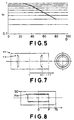
- Fig. 5 is a diagram showing the relation between the outer diameter D of the high permeability collar FM and shielding effect E.
- the magnetic field distribution Hi(Z), shown in Fig. 4 which is standardized by the magnetic field Hsc(120) at the center position of the cylinder SC, Z 120, is defined as shielding effect E, and in the diagram, E is expressed in terms of the outer diameter D of the high permeability collar FM.
- Fig. 6 is a schematic sectional view in which a high permeability collar FM is disposed in a superconductor cylinder SC of a single open end type.
- the high permeability collar FM is disposed at a position at 80 mm from the bottom surface of the superconductor cylinder SC of the single open end type.
- the dimensions of the cylinder are 100 mm in inner diameter, 120 mm in length and 5 mm in wall thickness.
- Those of the collar are 10 mm in length and 0.2 mm in thickness, and the permeability is 10000, and the outer diameter D is changed.
- Fig. 7 is a schematic sectional view in which a tapered collar of a high permeability material FM is disposed in a superconductor cylinder SC of a double open end type.
- the high permeability collar FM is disposed at a position at 80 mm apart from the center of the superconductor cylinder (SC) of the double open end type on each side.
- the dimensions of the cylinder are 100 mmin inner diameter, 240 mm in length, and 5 mm in wall thickness.
- Those of the collar are 80 mm in maximum diameter, 60 mm inminimum diameter, 10 mm in height, and 0.2 mm in thickness, and the permeability is 10000.
- Fig. 8 is a schematic sectional view in which a long collar of a high permeability material FM, the length of which 2P is selected, is disposed in a superconductor cylinder SC.
- the high permeability collar having the length of 2P is disposed in the vicinity of the center of the superconductor cylinder of double open end type composed of a bismuth group oxide (BiSrCaCuO).
- the dimensions of the cylinder are 100 mm in inner diameter, 150 mm in length, and 5 mm in wall thickness.
- Those of the collar are 75 mm in inner diameter, 2 mm in thickness and 2P mm in length, and the permeability is 10000.
- Fig. 9 is a diagram showing the internal magnetic field distribution on the axis of the superconductor cylinder SC when the length 2P of the high permeability collar FM is changed.
- the ordinate shows an internal magnetic field Hi and the abscissa shows the distance Z from the cylinder center.
- Fig. 10 is a diagram showing an internal magnetic field Hi when the length of the high permeability collar is changed variously.
- the ordinate shows an internal magnetic field Hi
- the abscissa shows the length P of the high permeability collar FM.
- the internal magnetic field Hi means a magnetic field at the center position of the collar.
- a line plotted with a mark ⁇ shows the result of the combination of the superconductor cylinder SC and the high permeability material FM
- a line plotted with a mark ⁇ shows the result of the case where a single collar FM of the high permeability material is tested alone.
- Fig. 11 is a schematic sectional view in which a pair of collars FM of the high permeability material having a several length L is disposed in a superconductor cylinder SC.
- the high permeability collars FM are disposed at a position 80 mm from the center on each side of the superconductor cylinder SC of a double open end type composed of a bismuth group oxide (BiSrCaCuO) (hereinafter referred to as a superconductor cylinder).
- the dimensions of the cylinder are 100 mm in inner diameter, 240 mm in length and 5 mm in wall thickness.
- Those of the collar are 70 mm in outer diameter and 0.2 mm in thickness, and the permeability is 10000, and the length L is changed.
- FIG. 12 is a diagram showing the relation between the length L of the high permeability collar FM and a shielding effect.
- the abscissa shows the length L of the high permeability collar FM. From the figure, it is understood that a shielding effect is improved more as the length of the high permeability collar FM is made longer.
- the high permeability collar FM When the high permeability collar FM is disposed in a inclination of the magnetic field inside the superconductor cylinder SC, since the high permeability material composing the collar has a finite permeability even though the length is made longer than a certain value it is magnetically saturated and the increase in magnetic induction becomes difficult, thereby the shielding effect will show a constant value.
- Fig. 13 is a schematic sectional view in which two pairs of the high permeability collars FM are arranged parallel in the longitudinal direction of the superconductor cylinder SC on its both sides.
- the figure is a schematic sectional view in which the high permeability collars FM are respectively disposed on each side at the positions 80 mm and 60 mm from the center of the superconductor cylinder SC of a double open end type composed of a bismuth group oxide (BiSrCaCuO) (hereinafterreferred to as a superconductor cylinder).
- the dimensions of the superconductor cylinder SC are 100 mmin inner diameter, 240 mm in length and 5 mm in wall thickness.
- Those of the high permeability collars FM are 70 mm in length and 0.2 mm in thickness, and the permeability is 10000.
- FIG. 14 is a diagram show ing the internal magnetic field distribution Hi(Z) on the axis of the superconductor cylinder SC in which tow paralal arrangement of the high permeability collars FM are disposed on the both sides.
- the ordinate shows the internal magnetic field Hi
- the abscissa shows the distance Z from the center of the superconductor cylinder SC.
- a line SC shows the internal magnetic distribution Hsc(Z) when a single superconductor cylinder is used without any high permeability collars FM
- an objective magnetic field can be obtained effectively and also at a low cost when a plurality of the high permeability collars are disposed in multiple arrangement in the superconductor cylinder SC leaving a space from the inner wall and being formed into a row at intervals in the longitudinal direction.
- Fig. 15 is a sectional view in which two pairs of coaxial collars of a high permeability material FM are disposed on both sides of a superconductor cylinder SC.
- each two collars FM of a high permeability material having different diameters from each other are disposed in the coaxial manner on each side at a position 80 mm from the center of the superconductor cylinder SC of double open end type composed of a bismuth group oxide (BiSrCaCuO) (hereinafter referred to as a superconductor cylinder).
- the dimensions of the superconductor cylinder SC are 100 mm in inner diameter, 240 mm in length and 5 mm in wall thickness.
- Those of the high permeability collars FM are 10 mm in length and 0.2 mm in thickness, and 80 mm and 60 mm in outer diameters respectively, and the permeability is 10000.
- FIG. 16 is a diagram showing an internal magnetic distribution Hi(Z) on the axis of the superconductor cylinder SC when each two collars FM are disposed in multiple layers in the radial direction.
- a line SC shows an internal magnetic field distribution Hsc(Z) when a single superconductor cylinder SC is used without any high permeability collars FM
- an objective magnetic field can be obtained effectively and at a low cost as in the case of the embodiment 4 in disposing the high permeability collar FM in parallelarrangement in the radial direction.
- Figs. 17A, 17B and 17C are schematic sectional views in which a plurality of high permeability collars FM are arranged in prallel in both the radial direction and the longitudinal direction.
- Fig. 17A shows a schematic sectional view of a construction in which a pair of sets of two collars are composed of a parallel arrange ment in radial direction.
- Fig. 17B shows a schematic sectional view of a constitution in which three pairs of sets of two short co e composed of a parallel arrangement in radial on and the three sets are disposed in a row in the longitudinal direction.
- Fig. 17C is a schematic sectional view in which small diameter collars and large diameter collars are alternately disposed in lamination.
- the collars having shapes as shown Figs. 17A to 17C are disposed inside a superconductor cylinder SC of double open end type composed of a bismuth group oxide (BiSrCaCuO) (hereinafter referred to as a superconductor cylinder).
- the dimensions of the superconductor cylinder SC are 100 mm in inner diameter, 240 mm in length and 5 mm in wall thickness.
- the permeability of all collars FM is 10000.
- a magnetic field distribution on the cylinder axis was measured in applying a uniform lateral magnetic field of 1 [G] to the superconductor cylinder SC.
- Fig. 17A shows a constitution in which a larger collars FM1 having an outer diameter of 80 mm and a length of 50 mm and a smaller collar FM2 having an outer diameter of 60 mm and a length of 50 mm are disposed in parallel arrangement in the radial direction.
- Fig. 17A shows a constitution in which a larger collars FM1 having an outer diameter of 80 mm and a length of 50 mm and a smaller collar FM2 having an outer diameter of 60 mm and a length of 50 mm are disposed in parallel arrangement in the radial direction.
- FIG. 17B shows a constitution in which three sets of short collars each composed of a larger collar FM1 having an outer diameter of 80 mm and a length of 10mm and a smaller collar FM2 having an outer diameter of 60 mm and a length of 10 mm, which are arranged in multiple layers in the radial direction, are disposed in a row at intervals in the longitudinal direction, the space occupied by the collars is made equal to that shown in Fig. 17A.
- Fig. 17C shows a constitution in which the collars composed of a larger collar FM1 having an outer diameter of 80 mm and a length of 10 mm and smaller collar FM2 having an outer diameter of 60 mm and a length of 10 mm, are alternately disposed in a staggered row in the longitudinal direction.
- Fig. 18 is a diagram showing the internal magnetic field distribution Hi(Z) on the axis of the superconductor cylinder SC when respective collars FM shown in Figs. 17A, 17B and 17C are disposed.
- the ordinate shows the internal magnetic field Hi
- the abscissa shows the distance Z from the center of the superconductor cylinder SC.
- a line SC shows the internal magnetic field distribution Hsc(Z) when a single superconductor cylinder SC is used without any of the collars FM
- a line plotted with a mark ⁇ shows what is shown in Fig. 17A
- a line plotted with a mark ⁇ shows what is shown in Fig. 17B
- a line plotted with a mark ⁇ shows what is shown in Fig. 17C.
- short collars FM are disposed being laminated at intervals, and respective collars FM are magnetically insulated, so that when the number of laminated collars is increased in the longitudinal direction a better shielding effect can be obtained.
- Fig. 17C is an example in which collars having different diameters from each other are alternately arranged in the longitudinal direction. In this case also a better shielding effect can be obtained than that obtained in the example shown in Fig. 17A owing to the arrangement of disposing collars at intervals in a row.
- two larger collars FM1 having diameters of 80 mm and three smaller collars FM2 having diameters of 60 mm are used in each pair, and it is easily inferred from the result of the embodiment 1 that when three larger collars having diameters of 80 mm and two smaller collars having diameters of 60 mm are used, a better shielding effect will be able to obtain than that obtained in the above example.
- Fig. 19 is an illustrative representation of another embodiment of the present invention.
- a additional shield cover system comprises an outer covering body 42 having the length of 150 cm and the inner covering bodies 43 and 44 having the lengths of 80 cm for covering the opening portion of the superconductor cylinder 41 having an inner diameter of a circular sectional portion of 1 m and a length of 2 m, and these covering bodies composed of a ferromagnetic material (Permalloy) of 5mm thick having diameters of 110 cm, 81 cm and 52 cm are concentrically fitted to the superconductor cylinder.
- Permalloy ferromagnetic material
- the magnetic field intensity at point A and point B shown in Fig. 19 was measured.
- the degrees of magnetic field intensity at both points were 10 ⁇ 4 and 4 x 10 ⁇ 8 times the external magnetic field intensity.
- a measurement was made removing the additional shield cover system, then it was found that the degrees of magnetic field intensity at A and B points shown in Fig. 19 were respectively 10 ⁇ 1 and 6 x 10 ⁇ 4 times the external magnetic field intensity.
Landscapes
- Physics & Mathematics (AREA)
- Health & Medical Sciences (AREA)
- Epidemiology (AREA)
- Condensed Matter Physics & Semiconductors (AREA)
- General Physics & Mathematics (AREA)
- Engineering & Computer Science (AREA)
- Microelectronics & Electronic Packaging (AREA)
- Shielding Devices Or Components To Electric Or Magnetic Fields (AREA)
- Superconductor Devices And Manufacturing Methods Thereof (AREA)
Applications Claiming Priority (7)
| Application Number | Priority Date | Filing Date | Title |
|---|---|---|---|
| JP25718990 | 1990-09-28 | ||
| JP2571/89 | 1990-09-28 | ||
| JP2263843A JP2795531B2 (ja) | 1990-10-03 | 1990-10-03 | 磁気シールド構造 |
| JP263843/90 | 1990-10-03 | ||
| JP80464/91 | 1991-03-20 | ||
| JP3080464A JP2825363B2 (ja) | 1990-09-28 | 1991-03-20 | 磁気シールド構造 |
| PCT/JP1991/001279 WO1992006576A1 (fr) | 1990-09-28 | 1991-09-26 | Structure de blindage magnetique |
Publications (3)
| Publication Number | Publication Date |
|---|---|
| EP0503085A1 true EP0503085A1 (de) | 1992-09-16 |
| EP0503085A4 EP0503085A4 (en) | 1993-03-17 |
| EP0503085B1 EP0503085B1 (de) | 1997-01-15 |
Family
ID=27303303
Family Applications (1)
| Application Number | Title | Priority Date | Filing Date |
|---|---|---|---|
| EP91916939A Expired - Lifetime EP0503085B1 (de) | 1990-09-28 | 1991-09-26 | Magnetische abschirmungsstruktur |
Country Status (5)
| Country | Link |
|---|---|
| US (1) | US6486393B1 (de) |
| EP (1) | EP0503085B1 (de) |
| CA (1) | CA2069637A1 (de) |
| DE (1) | DE69124221D1 (de) |
| WO (1) | WO1992006576A1 (de) |
Cited By (1)
| Publication number | Priority date | Publication date | Assignee | Title |
|---|---|---|---|---|
| EP2579431A3 (de) * | 2011-10-03 | 2017-06-14 | Rolls-Royce plc | Magnetabschirmung |
Families Citing this family (6)
| Publication number | Priority date | Publication date | Assignee | Title |
|---|---|---|---|---|
| US7026905B2 (en) * | 2000-05-24 | 2006-04-11 | Magtech As | Magnetically controlled inductive device |
| WO2004066836A1 (ja) * | 2003-01-29 | 2004-08-12 | National Institute Of Information And Communications Technology Incorporated Administrative Agency | 脳磁界計測装置とその使用方法 |
| US7305836B2 (en) * | 2004-05-19 | 2007-12-11 | Eden Innovations Ltd. | Cryogenic container and superconductivity magnetic energy storage (SMES) system |
| EP1829476B1 (de) * | 2004-12-20 | 2013-02-13 | National Institute of Information and Communications Technology | Messkonstruktion eines superleitenden magnetschild-gehirnfeld-messgeräts |
| US10755190B2 (en) | 2015-12-21 | 2020-08-25 | D-Wave Systems Inc. | Method of fabricating an electrical filter for use with superconducting-based computing systems |
| US12591029B2 (en) | 2022-03-07 | 2026-03-31 | D-Wave Systems Inc. | Thermally isolating cabling assemblies, systems using thermally isolating cabling assemblies, and methods of fabricating thermally isolating cabling assemblies |
Family Cites Families (11)
| Publication number | Priority date | Publication date | Assignee | Title |
|---|---|---|---|---|
| US2721995A (en) * | 1953-06-15 | 1955-10-25 | Magnetic Metals Company | Cathode ray tube shield structures |
| US3361940A (en) * | 1959-09-29 | 1968-01-02 | Rand Corp | Process of forming a super-conductive magnetic shield |
| JPS58148499A (ja) * | 1982-02-27 | 1983-09-03 | 富士通株式会社 | 超低温用磁気遮蔽容器 |
| JPS5990997A (ja) * | 1982-11-17 | 1984-05-25 | 富士通株式会社 | 磁気遮へい容器 |
| JP2527554B2 (ja) * | 1987-03-23 | 1996-08-28 | 大阪府 | 超電導磁気遮蔽体 |
| JPS63313900A (ja) * | 1987-06-17 | 1988-12-21 | Kawasaki Steel Corp | 複合超電導磁気遮蔽材料 |
| JPH01253690A (ja) * | 1988-04-01 | 1989-10-09 | Shimadzu Corp | 磁気シールド装置 |
| JPH03197897A (ja) * | 1989-12-26 | 1991-08-29 | Furukawa Electric Co Ltd:The | 超電導磁気シールド構造体 |
| JP2768815B2 (ja) * | 1990-09-27 | 1998-06-25 | 古河電気工業株式会社 | 磁気シールド構造 |
| US5466885A (en) * | 1990-09-27 | 1995-11-14 | Furukawa Denki Kogyo Kabushiki Kaisha | Magnetically shielding structure |
| JP3197897B2 (ja) | 1990-11-16 | 2001-08-13 | 株式会社壽 | シャープペンシル |
-
1991
- 1991-09-26 WO PCT/JP1991/001279 patent/WO1992006576A1/ja not_active Ceased
- 1991-09-26 DE DE69124221T patent/DE69124221D1/de not_active Expired - Lifetime
- 1991-09-26 EP EP91916939A patent/EP0503085B1/de not_active Expired - Lifetime
- 1991-09-26 CA CA002069637A patent/CA2069637A1/en not_active Abandoned
-
1994
- 1994-09-19 US US08/308,474 patent/US6486393B1/en not_active Expired - Fee Related
Cited By (1)
| Publication number | Priority date | Publication date | Assignee | Title |
|---|---|---|---|---|
| EP2579431A3 (de) * | 2011-10-03 | 2017-06-14 | Rolls-Royce plc | Magnetabschirmung |
Also Published As
| Publication number | Publication date |
|---|---|
| CA2069637A1 (en) | 1992-03-29 |
| US6486393B1 (en) | 2002-11-26 |
| WO1992006576A1 (fr) | 1992-04-16 |
| EP0503085A4 (en) | 1993-03-17 |
| DE69124221D1 (de) | 1997-02-27 |
| EP0503085B1 (de) | 1997-01-15 |
Similar Documents
| Publication | Publication Date | Title |
|---|---|---|
| US4409579A (en) | Superconducting magnetic shielding apparatus and method | |
| US4731598A (en) | Periodic permanent magnet structure with increased useful field | |
| EP1738376B1 (de) | Supraleitendes kabel und verfahren zur herstellung desselben | |
| EP0111218A2 (de) | Elektromagnet für die NMR-Tomographie | |
| EP0503085B1 (de) | Magnetische abschirmungsstruktur | |
| DE19947539B4 (de) | Gradientenspulenanordnung mit Dämpfung innerer mechanischer Schwingungen | |
| DE19653449C2 (de) | Gradientenspulenanordnung für ein Kernspintomographiegerät | |
| DE3900725C2 (de) | ||
| EP0485395A1 (de) | Supraleitende homogene hochfeldmagnetspule. | |
| DE3881982T2 (de) | Magnetischer Resonanzapparat mit schallarmer Gradientenspule. | |
| US5466885A (en) | Magnetically shielding structure | |
| DE19838390A1 (de) | Lärmreduziertes diagnostisches Magnetresonanzgerät | |
| US4912445A (en) | Electromagnet with a magnetic shield | |
| EP0424442B1 (de) | Wicklungsanordnung für einen kryomagneten | |
| DE4421335C2 (de) | Transversalgradientenspulensystem | |
| US4635017A (en) | Magnetic apparatus of a system for nuclear spin tomography with a shielding device | |
| US5543770A (en) | Apparatus for generating uniform and parallel magnetic field, the intensity of which is variable | |
| US5126713A (en) | Hemispherical cladding for permanent magnet solenoids | |
| DE69506011T2 (de) | Supraleitende Anordnung | |
| EP0288835B1 (de) | Magnetsystem einer Anlage zur Kernspintomographie mit supraleitenden Einzelspulen und einem Kälteschild | |
| EP0263242A1 (de) | Verzweigungszirkulator für Mikrowellen | |
| CH639772A5 (de) | Supraleitende spule fuer ein spektrometer. | |
| EP0503090B1 (de) | Magnetische abschirmungsstruktur | |
| US5317234A (en) | Mode trap for absorbing transverse modes of an accelerated electron beam | |
| US5805044A (en) | Field free chamber in permanent magnet solenoids |
Legal Events
| Date | Code | Title | Description |
|---|---|---|---|
| PUAI | Public reference made under article 153(3) epc to a published international application that has entered the european phase |
Free format text: ORIGINAL CODE: 0009012 |
|
| AK | Designated contracting states |
Kind code of ref document: A1 Designated state(s): DE FR GB |
|
| 17P | Request for examination filed |
Effective date: 19920928 |
|
| A4 | Supplementary search report drawn up and despatched | ||
| AK | Designated contracting states |
Kind code of ref document: A4 Designated state(s): DE FR GB |
|
| 17Q | First examination report despatched |
Effective date: 19940826 |
|
| GRAH | Despatch of communication of intention to grant a patent |
Free format text: ORIGINAL CODE: EPIDOS IGRA |
|
| GRAH | Despatch of communication of intention to grant a patent |
Free format text: ORIGINAL CODE: EPIDOS IGRA |
|
| GRAA | (expected) grant |
Free format text: ORIGINAL CODE: 0009210 |
|
| AK | Designated contracting states |
Kind code of ref document: B1 Designated state(s): DE FR GB |
|
| PG25 | Lapsed in a contracting state [announced via postgrant information from national office to epo] |
Ref country code: FR Effective date: 19970115 |
|
| REF | Corresponds to: |
Ref document number: 69124221 Country of ref document: DE Date of ref document: 19970227 |
|
| PG25 | Lapsed in a contracting state [announced via postgrant information from national office to epo] |
Ref country code: DE Effective date: 19970416 |
|
| EN | Fr: translation not filed | ||
| PG25 | Lapsed in a contracting state [announced via postgrant information from national office to epo] |
Ref country code: GB Free format text: LAPSE BECAUSE OF NON-PAYMENT OF DUE FEES Effective date: 19970926 |
|
| PLBE | No opposition filed within time limit |
Free format text: ORIGINAL CODE: 0009261 |
|
| STAA | Information on the status of an ep patent application or granted ep patent |
Free format text: STATUS: NO OPPOSITION FILED WITHIN TIME LIMIT |
|
| 26N | No opposition filed | ||
| GBPC | Gb: european patent ceased through non-payment of renewal fee |
Effective date: 19970926 |