EP0502263B2 - Stufenloses Getriebe mit verstellbarer Pumpe - Google Patents
Stufenloses Getriebe mit verstellbarer Pumpe Download PDFInfo
- Publication number
- EP0502263B2 EP0502263B2 EP91200987A EP91200987A EP0502263B2 EP 0502263 B2 EP0502263 B2 EP 0502263B2 EP 91200987 A EP91200987 A EP 91200987A EP 91200987 A EP91200987 A EP 91200987A EP 0502263 B2 EP0502263 B2 EP 0502263B2
- Authority
- EP
- European Patent Office
- Prior art keywords
- pump
- continuously variable
- variable transmission
- transmission according
- control means
- Prior art date
- Legal status (The legal status is an assumption and is not a legal conclusion. Google has not performed a legal analysis and makes no representation as to the accuracy of the status listed.)
- Expired - Lifetime
Links
- 230000005540 biological transmission Effects 0.000 title claims description 74
- 238000012384 transportation and delivery Methods 0.000 claims description 47
- 239000012530 fluid Substances 0.000 claims description 20
- 230000001133 acceleration Effects 0.000 claims description 7
- 230000001105 regulatory effect Effects 0.000 claims description 6
- 239000002131 composite material Substances 0.000 claims description 2
- 230000001419 dependent effect Effects 0.000 description 2
- 238000007599 discharging Methods 0.000 description 2
- 230000033228 biological regulation Effects 0.000 description 1
- 230000001276 controlling effect Effects 0.000 description 1
- 230000007423 decrease Effects 0.000 description 1
- 230000000994 depressogenic effect Effects 0.000 description 1
- 238000010586 diagram Methods 0.000 description 1
- XDDAORKBJWWYJS-UHFFFAOYSA-N glyphosate Chemical compound OC(=O)CNCP(O)(O)=O XDDAORKBJWWYJS-UHFFFAOYSA-N 0.000 description 1
- 238000009877 rendering Methods 0.000 description 1
Images


Classifications
-
- F—MECHANICAL ENGINEERING; LIGHTING; HEATING; WEAPONS; BLASTING
- F16—ENGINEERING ELEMENTS AND UNITS; GENERAL MEASURES FOR PRODUCING AND MAINTAINING EFFECTIVE FUNCTIONING OF MACHINES OR INSTALLATIONS; THERMAL INSULATION IN GENERAL
- F16H—GEARING
- F16H61/00—Control functions within control units of change-speed- or reversing-gearings for conveying rotary motion ; Control of exclusively fluid gearing, friction gearing, gearings with endless flexible members or other particular types of gearing
- F16H61/0021—Generation or control of line pressure
- F16H61/0025—Supply of control fluid; Pumps therefor
-
- F—MECHANICAL ENGINEERING; LIGHTING; HEATING; WEAPONS; BLASTING
- F16—ENGINEERING ELEMENTS AND UNITS; GENERAL MEASURES FOR PRODUCING AND MAINTAINING EFFECTIVE FUNCTIONING OF MACHINES OR INSTALLATIONS; THERMAL INSULATION IN GENERAL
- F16H—GEARING
- F16H61/00—Control functions within control units of change-speed- or reversing-gearings for conveying rotary motion ; Control of exclusively fluid gearing, friction gearing, gearings with endless flexible members or other particular types of gearing
- F16H61/66—Control functions within control units of change-speed- or reversing-gearings for conveying rotary motion ; Control of exclusively fluid gearing, friction gearing, gearings with endless flexible members or other particular types of gearing specially adapted for continuously variable gearings
- F16H61/662—Control functions within control units of change-speed- or reversing-gearings for conveying rotary motion ; Control of exclusively fluid gearing, friction gearing, gearings with endless flexible members or other particular types of gearing specially adapted for continuously variable gearings with endless flexible members
- F16H61/66272—Control functions within control units of change-speed- or reversing-gearings for conveying rotary motion ; Control of exclusively fluid gearing, friction gearing, gearings with endless flexible members or other particular types of gearing specially adapted for continuously variable gearings with endless flexible members characterised by means for controlling the torque transmitting capability of the gearing
-
- F—MECHANICAL ENGINEERING; LIGHTING; HEATING; WEAPONS; BLASTING
- F16—ENGINEERING ELEMENTS AND UNITS; GENERAL MEASURES FOR PRODUCING AND MAINTAINING EFFECTIVE FUNCTIONING OF MACHINES OR INSTALLATIONS; THERMAL INSULATION IN GENERAL
- F16H—GEARING
- F16H61/00—Control functions within control units of change-speed- or reversing-gearings for conveying rotary motion ; Control of exclusively fluid gearing, friction gearing, gearings with endless flexible members or other particular types of gearing
- F16H61/66—Control functions within control units of change-speed- or reversing-gearings for conveying rotary motion ; Control of exclusively fluid gearing, friction gearing, gearings with endless flexible members or other particular types of gearing specially adapted for continuously variable gearings
- F16H61/662—Control functions within control units of change-speed- or reversing-gearings for conveying rotary motion ; Control of exclusively fluid gearing, friction gearing, gearings with endless flexible members or other particular types of gearing specially adapted for continuously variable gearings with endless flexible members
- F16H2061/66286—Control for optimising pump efficiency
Definitions
- the invention relates to a continuously variable transmission provided with a primary pulley mounted on a primary shaft and a secondary pulley mounted on a secondary shaft, both the primary pulley and the secondary pulley comprising a pair of discs, at least one of said discs being axially movable by means of a hydraulic cylinder so as to adjust the transmission ratio, with a transmission means passed over the pulleys, with a pump means for providing a fluid for said hydraulic cylinder, which pump means have a regulable delivery and consist of at least two pump parts/poles, as well as control means to regulate the required pump delivery in dependence on the operating conditions of the transmission, said control means comprising a control valve which is disposed in a connecting line between the inlet and outlet of at least one pump part/pole.
- Such a continuously variable transmission is known from DE-C-3210759, and is in particular used in vehicles, but has other applications as well.
- the transmission ratio of the transmission is adjusted by the axial movement of at least one of the discs of the pulleys, as a result of which the effective radius of the transmission means between the pulleys is changed and the transmission ratio is changed accordingly.
- the axial movement of the discs is effected by means of hydraulic cylinders, which are fed with fluid by a pump.
- the pressure and/or the delivery of the fluid should at all times be such that the required axial movement of the discs is achieved, whilst moreover the transmission means is clamped between the pulleys in such a manner that no slip can occur between the transmission means and the pulleys.
- the pump means of the known transmission comprise two parallel pumps.
- the flow in the transmission can be chosen on basis of the full flow of one of the pumps and partly of the other pump or on basis of the pumps both for the full flow.
- the object of the invention is to overcome the drawbacks of the known continuously variable transmission which has an improved efficiency.
- the continuously variable transmission according to the invention is characterized in that the control valve is coupled to an on/off solenoid, so that the control valve is closed to pressurise the outlet or opened to render the outlet pressureless.
- the pump used according to the invention is preferably regulable in steps.
- the pump which is regulable in steps may be assembled of parallel pump parts, or be multi-polar.
- the pump parts or pump poles may thereby be arranged in such a manner that the pump part/-poles each have a different delivery.
- the continuously variable transmission is provided with control means which control the pump delivery dependently of the operating conditions of the transmission.
- Important operating conditions with this framework are the speeds of the primary and/or secondary shaft, as well as declerations and/or accelerations thereof, whether or not in their mutual ratios.
- data such as vehicle speed, acceleration, deceleration, accelerator pedal position and brake pedal positions as well as their derivatives in time can be used accordingly advantageously.
- the control means may be mechanical, hydraulic or electronic means, as well as combinations thereof.
- the electronic control means preferably also comprise selection means, whereby mutually different data are stored in the memory thereof, said data relating to a certain optimum choice with regard to the manner of regulating the pump delivery in relation to the operating conditions of the transmission.
- Figure 1 shows a hydraulic/mechanical continuously variable transmission such as is known from European Patent Specification No. 0,011,342. It will be apparent, however, that the invention may be used correspondingly in other types of continuously variable transmissions which are controlled by electronic, hydraulic or other means.
- the continuously variable transmission according to Figure 1 will be discussed within this framework so as to elucidate the continuously variable transmission per se.
- the continuously variable transmission comprises a primary shaft 1, e.g. driven by a motor of a vehicle, and has a fixed and an axially movable conical disc 2, 3, which together form the primary pulley.
- the disc 3 comprises the piston of cylinder 5 comprising the cylinder space 4, and may be axially moved by supplying and discharging fluid via the line 6.
- a secondary shaft 7 is present, which is e.g. connected to the wheels of a vehicle so as to drive the vehicle, and which is likewise provided with a fixed and an axially movable conical disc 8, 9, together forming the secondary pulley.
- the disc 9 is integrally connected to the cylinder 10, in which the piston 11 having a fixed connection to the secondary shaft 7 is present, so that the cylinder space 12 is enclosed.
- Via the line 13 fluid can be supplied to and discharged from the cylinder space 12.
- An endless transmission means 14, such as a thrust belt, chain or different driving belt is passed over the primary and the secondary pulley.
- the axial movement of the conical discs is effected by supplying or discharging fluid to or from the cylinder spaces 4 and 12.
- the pressure of the fluid in the cylinder space 12 is used to exert sufficient pressure on the endless transmission means 14, in order to prevent slip of the transmission means between the secondary and the primary pulley in this manner.
- the pressure and the delivery in the lines 6 and 13 to the cylinder spaces 4 and 12 are regulated by a control unit 20.
- This control unit may be a hydraulic, electronic or mechanical control unit, or a combination thereof.
- the required pressures and deliveries can be regulated by the control unit 20, on the basis of a multitude of variables (V1 - Vn) such as the transmission ratio, the speed of the primary/secondary shaft, the vehicle speed, accelerations and decelerations of the vehicle, accelerator pedal position etc.
- the control unit 20 is fed, via a line 21 coupled to the line 13, by a pump 15 sucking in fluid, e.g. from a reservoir 16 via a filter 19. The pump thereby puts the fluid under a certain pressure. Any excess fluid is discharged by the control unit via the line 22.
- the pump delivery required for the pressure on the transmission means and for controlling the transmission ratio of the continuously variable transmission varies strongly, dependent on the operating conditions of the transmission.
- a few examples of operating conditions in combination with the pump delivery in dependence on the rpm of the primary shaft are shown in Figure 2.
- Normal driving conditions are indicated by the line 23.
- Line 24 indicates the course of the required pump delivery in case of an an emergency stop.
- the required pump delivery strongly increases thereby, since the transmission must change down very quickly in order to make it possible to drive off quickly again, which may be required for safety reasons.
- so-called "kick-down" actions when the accelerator pedal is depressed completely, e.g. when overtaking a vehicle, a substantial delivery is required, both in the low rpm range (line 25) and in the high rpm range (line 26).
- the pump according to prior art such as e.g. described in European Patent Specification No. 0,011,342, is selected such that the pump delivery is larger than the maximum delivery required. This means that the known pump is strongly overdimensioned and that substantial efficiency losses occur in the transmission, because in practically all operating conditions the pump circulates more fluid than is necessary.
- a pump with a regulable delivery such as a continuously variable pump or a pump which is variable in steps, e.g. a composite pump or a multi-polar pump.
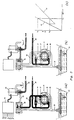
- FIG. 3 shows an embodiment of the invention having a bipolar roller vanes pump 31.
- the pump 31 sucks fluid from the reservoir 33 via the line 32 by means of two inlets 34, 35, and discharges medium via outlets 36 and 37 respectively.
- the fluid between the inlet 34 and the outlet 36, as well as between the inlet 35 and the outlet 37 is pressurized.
- the pump 31 may furthermore be designed such that the deliveries between inlets/outlets 34, 36 and 35, 37 are different and determine the entire pump delivery e.g. in a ratio of 60/40 %.
- the medium pressurized by the pump is discharged to the transmission via the line 38.
- the pump delivery is regulable by rendering one or more pump poles pressureless.
- the pump pole having inlet/outlet 35, 37 can be rendered pressureless by communicating the outlet 37 with the inlet 35.
- a control valve 39 is provided in a line 40, which is connected to the outlet 37.
- the control valve 39 is illustrated in closed condition, so that no fluid is allowed to flow to the line 32 via the line 40.
- the pump pole with the inlet 35 and the outlet 37 is pressurized and fluid is discharged to the transmission via the line 38.
- the control valve is shown in open condition, however, so that fluid can flow to the line 32 via the line 40 and the control valve 39.
- the pump pole with the inlet 35 and the outlet 37 has become pressureless, and therefore does not take part in the pump delivery provided by the pump.
- a non-return valve is provided in the connection between the outlet 36 and the outlet 37.
- the pump delivery is regulable. This is illustrated once more in Figure 3c.
- the line 42 thereby indicates the delivery provided by the pump in dependence on the rpm if only one pump pole is used, the pole with the inlet 34 and the outlet 36 in this case.
- Line 43 indicates the delivery supplied by the pump if both pump poles (inlet/outlet 34, 36 and inlet/outlet 35, 37) are operated.
- the delivery of the two poles can be selected differently (e.g. 60/40 %) by adapting the pump design, so that the angle of inclination of the lines 42 and 43 may vary.
- Figure 3C shows an example whereby up to a certain rpm N1 both pumps are connected and whereby above said rpm only one pump pole provides a delivery, as a result of which the entire delivery provided by the pump decreases from D1 to D2, and from there increases along with the rpm again.
- the pump provides a substantially smaller delivery across a certain rpm range than is the case when both pump poles are operative.
- the efficiency loss of the transmission as a result of the pump power consumed has been considerably reduced.
- the pump may also be controlled on the basis of a large number of variables, such as the speed of the primary shaft (Np) and or the secondary shaft (Ns) of the transmission, as well as accelerations or decelerations ( ⁇ 1) thereof.
- variables such as vehicle speed (V1), engine rpm (Nm), accelerations or decelerations ( ⁇ 2) thereof, as well as the accelerator pedal position ( ⁇ ) and brake pedal position, or the derivatives in time thereof, can be used.
- V1 vehicle speed
- Nm engine rpm
- ⁇ 2 accelerations or decelerations
- ⁇ accelerator pedal position
- brake pedal position or the derivatives in time thereof
- Figure 3 shows an electronic control unit with selection means 44, which is fed with one or more of the above variables.
- the control unit 44 comprises selection means, in whose memory data are stored relating to a certain optimum selection with regard to the manner of regulating the pump delivery in relation to the aforesaid variables to be input as a measure of the specific momentaneous operating condition of the transmission.
- the pump characteristic according to Figure 4 may be stored in the memory of the selection means, as a relation between the line pressure p and the rpm Np of the primary shaft.
- the selection means may thereby be arranged in such a manner that in the range 45' both poles of the pump 31 are used at all times, whilst in the range 46' one single pole of the pump 31 is used at all times.
- the selection means may then determine, on the basis of the other variables which are input as a measure of the momentaneous operating conditions of the transmission, whether one or both poles of the pump 31 will be used.
- the selection means compare the input value with a limit value or differential value stored in the memory whereby, when said values are exceeded, the control means are activated and the pump delivery is thus adapted.
- the control means compare e.g. the accelerator pedal position or the derivative in time with a stored limit value thereof.
- the required speed of the primary shaft is compared with the actual speed of the primary shaft.
- the control means could be activated.
- the variables may be standardized e.g. by transmission variables with corresponding vehicle variables.
- control unit 44 delivers a signal to an on/off solenoid 45, which is disposed in a line 46.
- the on/off solenoid 45 may thereby open or close the connection between the line 46 and a line 47 to the control valve 39.
- the control valve 39 is closed ( Figure 3b), resulting in only one pump pole being used, or opened ( Figure 3a), resulting in both pump poles being used.
- the illustrated embodiment shows a pump having two pump poles. Otherwise all this is correspondingly applicable to assembled pumps, in which one or more pumps are provided in parallel and one or more pumps may be selectively connected or disconnected or be rendered pressureless. As will be apparent the best regulability is achieved when using a continuously variable pump. The invention is thus not limited to the illustrated embodiment.
Landscapes
- Engineering & Computer Science (AREA)
- General Engineering & Computer Science (AREA)
- Mechanical Engineering (AREA)
- Control Of Transmission Device (AREA)
- Transmissions By Endless Flexible Members (AREA)
Claims (19)
- Stufenloses Getriebe mit einer ersten Riemenscheibe, die auf einer Antriebswelle (1) befestigt ist, und einer zweiten Riemenscheibe, die auf einer Abtriebswelle (7) befestigt ist, wobei sowohl die erste als auch die zweite Riemenscheibe ein Paar von Scheiben (2, 3, 8, 9) aufweist, von denen jeweils wenigstens eine Scheibe (3, 9) mit Hilfe eines hydraulischen Zylinders (5, 10) axial so bewegbar ist, daß das Übersetzungsverhältnis eingestellt werden kann, einer Übertragungsvorrichtung (14), die über die Riemenscheiben läuft, einer Pumpe (15; 31) zum Bereitstellen eines Fluids für den hydraulischen Zylinder, wobei die Pumpe einen steuerbaren Ausstoß hat und aus zumindest zwei Pumpenteilen oder -polen besteht, als auch einer Steuervorrichtung (20; 44), um den benötigten Pumpenausstoß in Abhängigkeit von den Betriebsbedingungen des Getriebes zu steuern, wobei die Steuervorrichtung (44) ein Steuerventil (39) umfaßt, das in einer Verbindungsleitung (40) zwischen dem Einlaß (34; 35) und dem Auslaß (36; 37) wenigstens eines Pumpenteiles oder -poles liegt, dadurch gekennzeichnet, daß das Steuerventil (39) mit einem Ein- und Ausschalt-Elektromagneten (45) so verbunden ist, daß das Steuerventil (39) geschlossen ist, um den Auslaß (36; 37) unter Druck zu setzen, oder geöffnet ist, um den Auslaß (36; 37) drucklos zu machen.
- Stufenloses Getriebe nach Anspruch 1, dadurch gekennzeichnet, daß der Ein- und Ausschalt-Elektromagnet (45) mit einem Ausgang einer Auswahlvorrichtung gekoppelt ist.
- Stufenloses Getriebe nach Anspruch 1, dadurch gekennzeichnet, daß die Steuervorrichtung den benötigten Pumpenausstoß in Abhängigkeit von einem oder von mehreren der folgenden Betriebszustände steuert: der Geschwindigkeit der Antriebswelle (NP), der Geschwindigkeit der Abtriebswelle (Ns) ebenso wie der Beschleunigung oder Verzögerung (α 1) dieser Teile und vom Leitungsdruck (P) im Getriebe.
- Stufenloses Getriebe nach Anspruch 1, dadurch gekennzeichnet, daß die Steuervorrichtung den benötigten Pumpenausstoß in Abhängigkeit von einem oder mehreren Betriebszuständen des Fahrzeuges steuert, beispielsweise von der Motordrehzahl (Nm), der Fahrzeuggeschwindigkeit (V1), deren Beschleunigung oder Verzögerung (α 2) und den Stellungen des Gaspedals oder des Bremspedals und deren zeitliche Ableitungen.
- Stufenloses Getriebe nach einem der Vorangegangenen Ansprüche, dadurch gekennzeichnet, daß die Steuervorrichtung (44) eine hydromechanische Steuervorrichtung ist.
- Stufenloses Getriebe nach einem der vorangegangenen Ansprüche, dadurch gekennzeichnet, daß die Steuervorrichtung (44) eine hydraulische Vorrichtung ist.
- Stufenloses Getriebe nach einem der Vorangegangenen Ansprüche, dadurch gekennzeichnet, daß die Steuervorrichtung (44) eine elektronische Vorrichtung ist.
- Stufenloses Getriebe nach einem der vorangegangenen Ansprüche, dadurch gekennzeichnet, daß die elektronische Steuervorrichtung eine Auswahlvorrichtung enthält, wobei in deren Speicher wechselweise unterschiedliche Daten gespeichert werden, wobei diese Daten eine bestimmte, optimale Auswahl in bezug auf die Regulierungsart des Pumpenausstoßes in bezug auf die Betriebsbedingungen des Getriebes betreffen.
- Stufenloses Getriebe nach Anspruch 8, dadurch gekennzeichnet, daß in den Einlaß der Auswahlvorrichtung ein Eingangssignal als Meßergebnis der Stellung (β) des Gaspedals eingeleitet wird und mit einem Grenzwert davon (β Limit) verglichen wird, der im Speicher gespeichert ist und daß dann, wenn der Grenzwert überschritten wird, die Steuervorrichtung (44) dazu gebracht werden kann, den Pumpenausstoß anzupassen.
- Stufenloses Getriebe nach Anspruch 8, dadurch gekennzeichnet, daß an den Eingang der Auswahlvorrichtung ein Eingangssignal als Meßergebnis der Veränderung der Stellung (β) des Gaspedals eingeleitet wird und mit einem Grenzwert davon (β Limit) verglichen wird, der im Speicher gespeichert ist und daß dann, wenn der Grenzwert überschritten wird, die Steuervorrichtung (44) dazu gebracht werden kann, den Pumpenausstoß anzupassen.
- Stufenloses Getriebe nach Anspruch 8, dadurch gekennzeichnet, daß an den Eingang der Steuervorrichtung ein Eingangssignal als Meßergebnis der benötigten Geschwindigkeit der Antriebswelle (Np Sollwert) eingeleitet wird und mit einem Eingangssignal als Meßergebnis der tatsächlichen Geschwindigkeit der Eingangswelle (Np Istwert) verglichen wird sowie mit einem Differentialwert, der im Speicher gespeichert ist und daß dann, wenn der Differentialwert überschritten wird, die Steuervorrichtung (44) aktiviert wird, um den Pumpenausstoß anzupassen.
- Stufenloses Getriebe nach Anspruch 11, dadurch gekennzeichnet, daß die Eingangssignale für die benötigte und die tatsächliche Geschwindigkeit der Antriebswelle jeweils für die benötigte und die tatsächliche Fahrzeuggeschwindigkeit standardisiert sind.
- Stufenloses Getriebe nach Anspruch 8, dadurch gekennzeichnet, daß dem Eingang der Auswahlvorrichtung ein Eingangssignal als Meßergebnis der Verzögerung des Fahrzeuges zugeleitet wird und daß es mit einem Verzögerungswert verglichen wird, der im Speicher gespeichert wird und daß dann, wenn der Verzögerungswert überschritten wird, die Steuervorrichtung (44) aktiviert werden kann, um den Pumpenausstoß anzupassen.
- Stufenloses Getriebe nach Anspruch 8, dadurch gekennzeichnet, daß die Pumpencharakteristik im Speicher der Auswahlvorrichtung gespeichert ist.
- Stufenloses Getriebe nach Anspruch 1, dadurch gekennzeichnet, daß der Ausstoß der Pumpe (31) in Schritten regelbar ist.
- Stufenloses Getriebe nach Anspruch 15 dadurch gekennzeichnet, daß die Pumpe (31) eine zusammengesetzte Pumpe mit parallelen Pumpenteilen ist.
- Stufenloses Getriebe nach Anspruch 15, dadurch gekennzeichnet, daß die Pumpe (31) mehrpolig ist.
- Stufenloses Getriebe nach Anspruch 17, dadurch gekennzeichnet, daß die Pumpe (31) zweipolig ist.
- Stufenloses Getriebe nach einem der Ansprüche 15 bis 18, dadurch gekennzeichnet, daß die Pumpenteile oder -pole (34, 36; 35, 37) jeweils unterschiedliche Ausstoßmengen haben.
Applications Claiming Priority (2)
| Application Number | Priority Date | Filing Date | Title |
|---|---|---|---|
| NL9100391A NL9100391A (nl) | 1991-03-05 | 1991-03-05 | Continu variabele transmissie voorzien van een regelbare pomp. |
| NL9100391 | 1991-03-05 |
Publications (3)
| Publication Number | Publication Date |
|---|---|
| EP0502263A1 EP0502263A1 (de) | 1992-09-09 |
| EP0502263B1 EP0502263B1 (de) | 1994-09-14 |
| EP0502263B2 true EP0502263B2 (de) | 2000-09-20 |
Family
ID=19858973
Family Applications (1)
| Application Number | Title | Priority Date | Filing Date |
|---|---|---|---|
| EP91200987A Expired - Lifetime EP0502263B2 (de) | 1991-03-05 | 1991-04-25 | Stufenloses Getriebe mit verstellbarer Pumpe |
Country Status (5)
| Country | Link |
|---|---|
| US (1) | US5137498A (de) |
| EP (1) | EP0502263B2 (de) |
| JP (1) | JP3307659B2 (de) |
| DE (1) | DE69104024T3 (de) |
| NL (1) | NL9100391A (de) |
Families Citing this family (16)
| Publication number | Priority date | Publication date | Assignee | Title |
|---|---|---|---|---|
| NL1001279C2 (nl) * | 1995-09-25 | 1997-03-26 | Doornes Transmissie Bv | Continu variabele transmissie. |
| NL1003876C2 (nl) * | 1996-08-26 | 1998-03-03 | Doornes Transmissie Bv | Continu variabele transmissie met tenminste twee pompen in serie-/parallelschakeling. |
| DE19756685C2 (de) * | 1997-12-19 | 1999-10-28 | Zahnradfabrik Friedrichshafen | Automatgetriebe |
| DE19904593A1 (de) * | 1999-02-05 | 2000-08-10 | Zf Batavia Llc | Automatgetriebe |
| DE19924855A1 (de) * | 1999-04-30 | 2000-11-02 | Hydraulik Ring Gmbh | Druckmittelversorgung eines CVT-Getriebes |
| EP1048879B1 (de) * | 1999-04-30 | 2004-06-23 | Hydraulik-Ring GmbH | Druckmittelversorgung eines CVT-Getriebes |
| US6386836B1 (en) | 2000-01-20 | 2002-05-14 | Eagle-Picher Industries, Inc. | Dual gerotor pump for use with automatic transmission |
| US6641372B2 (en) * | 2000-01-21 | 2003-11-04 | Delphi Technologies, Inc. | Dual discharge hydraulic pump and system therefor |
| DE10020187A1 (de) * | 2000-04-25 | 2001-10-31 | Getrag Getriebe Zahnrad | Hydraulische Schaltung für ein automatisiertes Doppelkupplungsgetriebe für Kraftfahrzeuge |
| EP1497574B1 (de) | 2002-04-10 | 2006-04-19 | LuK Lamellen und Kupplungsbau Beteiligungs KG | Hydrauliksystem, automatikgetriebe |
| KR100486636B1 (ko) * | 2002-06-28 | 2005-05-03 | 고등기술연구원연구조합 | 조향계의 진동 재현장치 |
| EP1482215B1 (de) | 2003-05-30 | 2006-10-04 | Robert Bosch Gmbh | Hydraulische Anordnung für Fahrzeuggetriebe |
| JP2008510105A (ja) * | 2004-08-13 | 2008-04-03 | ロベルト ボッシュ ゲゼルシャフト ミト ベシュレンクテル ハフツング | 液圧ポンプセットの設けられた連続可変トランスミッション |
| DE502005002557D1 (de) * | 2004-11-27 | 2008-03-06 | Luk Lamellen & Kupplungsbau | Verfahren und Vorrichtung zum Ermitteln einer eine Übertragungssicherheit zwischen zwei durch Reibeingriff eine Bewegung übertragenden Bauteilen beschreibende Übertragungsgröße |
| US8042331B2 (en) | 2008-04-01 | 2011-10-25 | GM Global Technology Operations LLC | On-demand hydraulic pump for a transmission and method of operation |
| JP5922416B2 (ja) * | 2012-01-23 | 2016-05-24 | 本田技研工業株式会社 | 可変容量ポンプの運転状態切換装置 |
Family Cites Families (5)
| Publication number | Priority date | Publication date | Assignee | Title |
|---|---|---|---|---|
| NL7811192A (nl) * | 1978-11-13 | 1980-05-16 | Doornes Transmissie Bv | Werkwijze en inrichting voor het regelen van een trap- loos variabele transmissie van een motorvoertuig. |
| JPH066974B2 (ja) * | 1982-10-22 | 1994-01-26 | 日産自動車株式会社 | Vベルト式無段変速機の油圧制御装置 |
| NL8403461A (nl) * | 1984-11-13 | 1986-06-02 | Doornes Transmissie Bv | Traploos variabele overbrenging. |
| DE3727633A1 (de) * | 1987-08-19 | 1989-03-02 | Manfred Rattunde | Kegelscheibenumschlingungsgetriebe mit geregelter druckmittelmenge |
| JPH01135956A (ja) * | 1987-11-19 | 1989-05-29 | Yuken Kogyo Kk | ベルト式無段変速機用油圧制御装置 |
-
1991
- 1991-03-05 NL NL9100391A patent/NL9100391A/nl active Search and Examination
- 1991-04-25 DE DE69104024T patent/DE69104024T3/de not_active Expired - Lifetime
- 1991-04-25 EP EP91200987A patent/EP0502263B2/de not_active Expired - Lifetime
- 1991-05-10 US US07/698,625 patent/US5137498A/en not_active Expired - Lifetime
- 1991-05-20 JP JP14261891A patent/JP3307659B2/ja not_active Expired - Lifetime
Also Published As
| Publication number | Publication date |
|---|---|
| EP0502263A1 (de) | 1992-09-09 |
| EP0502263B1 (de) | 1994-09-14 |
| US5137498A (en) | 1992-08-11 |
| NL9100391A (nl) | 1992-10-01 |
| JPH04277366A (ja) | 1992-10-02 |
| DE69104024T3 (de) | 2001-02-22 |
| DE69104024T2 (de) | 1995-01-26 |
| DE69104024D1 (de) | 1994-10-20 |
| JP3307659B2 (ja) | 2002-07-24 |
Similar Documents
| Publication | Publication Date | Title |
|---|---|---|
| EP0502263B2 (de) | Stufenloses Getriebe mit verstellbarer Pumpe | |
| US4733582A (en) | Control valve system for a continuously variable belt driven transmission for motor vehicles | |
| US4462277A (en) | Hydraulic regulator for a V-belt type continuously variable transmission for vehicles | |
| EP0117696B1 (de) | Hydraulische Einrichtung für einen stufenlos einstellbaren Antrieb | |
| JPH0242696B2 (de) | ||
| US4887428A (en) | Hydraulic control device for a continuously variable transmission for motor vehicles | |
| GB2058256A (en) | Control apparatus for a stepless transmission | |
| JP3688101B2 (ja) | 連続可変変速機 | |
| KR101067603B1 (ko) | 차량을 구동하기 위한 구동 트레인 | |
| JP4608102B2 (ja) | 無段変速式の伝動装置のためのハイドロリック制御装置 | |
| US4850813A (en) | Self unloading pump circuit for an automatic transmission having multiple pressure supply pumps | |
| JP4616995B2 (ja) | 無段変速機のためのハイドロリック制御装置 | |
| JPH11182666A (ja) | ベルト式無段変速機の油圧制御装置 | |
| JPH05280629A (ja) | 円錐形プーリ式無段変速機 | |
| US4662493A (en) | Direct-coupling control system for torque converter in automatic transmission for vehicles | |
| JP2003517540A (ja) | 自動変速装置 | |
| EP0452353A1 (de) | Regelsystem des öldruckes eines automatischen getriebes. | |
| US4222469A (en) | Inching control system for industrial lift trucks | |
| JPS61215853A (ja) | 車両用ベルト式無段変速機の油圧制御装置 | |
| JPH08270789A (ja) | 油圧可変容量形ポンプの自動車方式駆動制御装置 | |
| KR100357553B1 (ko) | 차량용 무단 변속기의 유압 제어 시스템 | |
| KR100279428B1 (ko) | 자동차용 무단변속기의 유압 제어시스템 | |
| KR100211362B1 (ko) | 자동 변속기용 라인압 저하 보상장치 | |
| KR100504419B1 (ko) | 무단변속시에일정한클램핑력비율을조절하는비상유압제어장치 | |
| JPH11182667A (ja) | ベルト式無段変速機の油圧制御装置 |
Legal Events
| Date | Code | Title | Description |
|---|---|---|---|
| PUAI | Public reference made under article 153(3) epc to a published international application that has entered the european phase |
Free format text: ORIGINAL CODE: 0009012 |
|
| 17P | Request for examination filed |
Effective date: 19910425 |
|
| AK | Designated contracting states |
Kind code of ref document: A1 Designated state(s): BE DE ES FR GB IT NL SE |
|
| 17Q | First examination report despatched |
Effective date: 19931004 |
|
| GRAA | (expected) grant |
Free format text: ORIGINAL CODE: 0009210 |
|
| AK | Designated contracting states |
Kind code of ref document: B1 Designated state(s): BE DE ES FR GB IT NL SE |
|
| REF | Corresponds to: |
Ref document number: 69104024 Country of ref document: DE Date of ref document: 19941020 |
|
| ITF | It: translation for a ep patent filed | ||
| PG25 | Lapsed in a contracting state [announced via postgrant information from national office to epo] |
Ref country code: SE Effective date: 19941214 |
|
| ET | Fr: translation filed | ||
| PLBI | Opposition filed |
Free format text: ORIGINAL CODE: 0009260 |
|
| 26 | Opposition filed |
Opponent name: P.I.V. ANTRIEB WERNER REIMERS GMBH & CO. KG Effective date: 19950610 |
|
| NLR1 | Nl: opposition has been filed with the epo |
Opponent name: P.I.V. ANTRIEB WERNER REIMERS GMBH & CO. KG |
|
| PLBF | Reply of patent proprietor to notice(s) of opposition |
Free format text: ORIGINAL CODE: EPIDOS OBSO |
|
| APAC | Appeal dossier modified |
Free format text: ORIGINAL CODE: EPIDOS NOAPO |
|
| APAE | Appeal reference modified |
Free format text: ORIGINAL CODE: EPIDOS REFNO |
|
| APCC | Communication from the board of appeal sent |
Free format text: ORIGINAL CODE: EPIDOS OBAPO |
|
| APCC | Communication from the board of appeal sent |
Free format text: ORIGINAL CODE: EPIDOS OBAPO |
|
| APAC | Appeal dossier modified |
Free format text: ORIGINAL CODE: EPIDOS NOAPO |
|
| PLAW | Interlocutory decision in opposition |
Free format text: ORIGINAL CODE: EPIDOS IDOP |
|
| PLAW | Interlocutory decision in opposition |
Free format text: ORIGINAL CODE: EPIDOS IDOP |
|
| PUAH | Patent maintained in amended form |
Free format text: ORIGINAL CODE: 0009272 |
|
| STAA | Information on the status of an ep patent application or granted ep patent |
Free format text: STATUS: PATENT MAINTAINED AS AMENDED |
|
| 27A | Patent maintained in amended form |
Effective date: 20000920 |
|
| AK | Designated contracting states |
Kind code of ref document: B2 Designated state(s): BE DE ES FR GB IT NL SE |
|
| NLR2 | Nl: decision of opposition | ||
| PG25 | Lapsed in a contracting state [announced via postgrant information from national office to epo] |
Ref country code: ES Free format text: LAPSE BECAUSE OF FAILURE TO SUBMIT A TRANSLATION OF THE DESCRIPTION OR TO PAY THE FEE WITHIN THE PRESCRIBED TIME-LIMIT Effective date: 20001231 |
|
| ET3 | Fr: translation filed ** decision concerning opposition | ||
| NLR3 | Nl: receipt of modified translations in the netherlands language after an opposition procedure | ||
| REG | Reference to a national code |
Ref country code: GB Ref legal event code: IF02 |
|
| APAH | Appeal reference modified |
Free format text: ORIGINAL CODE: EPIDOSCREFNO |
|
| PGFP | Annual fee paid to national office [announced via postgrant information from national office to epo] |
Ref country code: IT Payment date: 20070607 Year of fee payment: 17 |
|
| PG25 | Lapsed in a contracting state [announced via postgrant information from national office to epo] |
Ref country code: ES Free format text: LAPSE BECAUSE OF FAILURE TO SUBMIT A TRANSLATION OF THE DESCRIPTION OR TO PAY THE FEE WITHIN THE PRESCRIBED TIME-LIMIT Effective date: 19950430 |
|
| PG25 | Lapsed in a contracting state [announced via postgrant information from national office to epo] |
Ref country code: IT Free format text: LAPSE BECAUSE OF NON-PAYMENT OF DUE FEES Effective date: 20080425 |
|
| PGFP | Annual fee paid to national office [announced via postgrant information from national office to epo] |
Ref country code: GB Payment date: 20100324 Year of fee payment: 20 |
|
| PGFP | Annual fee paid to national office [announced via postgrant information from national office to epo] |
Ref country code: FR Payment date: 20100506 Year of fee payment: 20 |
|
| PGFP | Annual fee paid to national office [announced via postgrant information from national office to epo] |
Ref country code: NL Payment date: 20100421 Year of fee payment: 20 |
|
| PGFP | Annual fee paid to national office [announced via postgrant information from national office to epo] |
Ref country code: BE Payment date: 20100423 Year of fee payment: 20 |
|
| PGFP | Annual fee paid to national office [announced via postgrant information from national office to epo] |
Ref country code: DE Payment date: 20100623 Year of fee payment: 20 |
|
| REG | Reference to a national code |
Ref country code: DE Ref legal event code: R071 Ref document number: 69104024 Country of ref document: DE |
|
| BE20 | Be: patent expired |
Owner name: *VAN DOORNE'S TRANSMISSIE B.V. Effective date: 20110425 |
|
| REG | Reference to a national code |
Ref country code: NL Ref legal event code: V4 Effective date: 20110425 |
|
| REG | Reference to a national code |
Ref country code: GB Ref legal event code: PE20 Expiry date: 20110424 |
|
| PG25 | Lapsed in a contracting state [announced via postgrant information from national office to epo] |
Ref country code: GB Free format text: LAPSE BECAUSE OF EXPIRATION OF PROTECTION Effective date: 20110424 Ref country code: NL Free format text: LAPSE BECAUSE OF EXPIRATION OF PROTECTION Effective date: 20110425 |
|
| PG25 | Lapsed in a contracting state [announced via postgrant information from national office to epo] |
Ref country code: DE Free format text: LAPSE BECAUSE OF EXPIRATION OF PROTECTION Effective date: 20110425 |