EP0501555A1 - Steuerungsverfahren der Bremsleuchten und Trägheitseinrichtung zur Signalerzeugung - Google Patents
Steuerungsverfahren der Bremsleuchten und Trägheitseinrichtung zur Signalerzeugung Download PDFInfo
- Publication number
- EP0501555A1 EP0501555A1 EP92200430A EP92200430A EP0501555A1 EP 0501555 A1 EP0501555 A1 EP 0501555A1 EP 92200430 A EP92200430 A EP 92200430A EP 92200430 A EP92200430 A EP 92200430A EP 0501555 A1 EP0501555 A1 EP 0501555A1
- Authority
- EP
- European Patent Office
- Prior art keywords
- signal
- pedal
- electric
- sensor
- brake lights
- Prior art date
- Legal status (The legal status is an assumption and is not a legal conclusion. Google has not performed a legal analysis and makes no representation as to the accuracy of the status listed.)
- Granted
Links
Images


Classifications
-
- B—PERFORMING OPERATIONS; TRANSPORTING
- B60—VEHICLES IN GENERAL
- B60Q—ARRANGEMENT OF SIGNALLING OR LIGHTING DEVICES, THE MOUNTING OR SUPPORTING THEREOF OR CIRCUITS THEREFOR, FOR VEHICLES IN GENERAL
- B60Q1/00—Arrangement of optical signalling or lighting devices, the mounting or supporting thereof or circuits therefor
- B60Q1/26—Arrangement of optical signalling or lighting devices, the mounting or supporting thereof or circuits therefor the devices being primarily intended to indicate the vehicle, or parts thereof, or to give signals, to other traffic
- B60Q1/44—Arrangement of optical signalling or lighting devices, the mounting or supporting thereof or circuits therefor the devices being primarily intended to indicate the vehicle, or parts thereof, or to give signals, to other traffic for indicating braking action or preparation for braking, e.g. by detection of the foot approaching the brake pedal
- B60Q1/441—Electric switches operable by the driver's pedals
Definitions
- the present invention relates to a safety system for the activation of brake lights of a car before actual braking takes place.
- the invention relates to an inertial signal-generating device of improved design.
- Inertial signal-generating devices are also known in the art, and generally comprise an element which is free to bend under inertial forces, and the bending of which causes a change in electrical properties of this element, or of an additional memeber connected thereto, which is in turn connected to electrical connections.
- the change in electrical properties e.g., conductivity, causes a change in the electrical signal emitted by the signal-generating device, thereby alerting receiving means, which receive this signal and detect the change, indicating that inertial forces have been applied to the signal-generating device.
- Such signal-generating devices have a variety of applications, for instance, in crash analysis, or in industry to analyze different dynamical behaviors of different moving parts, and for many other purposes which will be appreciated by the skilled engineer.
- a particular use is that described in which the inertial signal-generating device is exploited in a brake light activation system, to activate a circuit which causes the brake lights to light up when the acceleration pedal is suddenly released, and before the brake is actually actuated.
- the inertial signal-generating device detects the sudden and abrupt release of the pedal, and generates a signal which is analyzed by appropriate electronic circuits.
- US-A-4 894 652 discloses the system ABLD, (Advanced Brake Light Device) shown in Fig. 2, which utilizes an electromagnetic or pneumatic sensor 12 mounted on the accelerator pedal, the driver's foot resting upon it.
- ABLD Advanced Brake Light Device
- the principle of the sensor is, in one version, the vacuum level produced by the driver's foot. In another version, it is based on the electromagnetic signal produced by the movement of a ferromagnetic part in front of an electric coil.
- the senor When the dirver's foot is removed from the accelerator, the sensor produces a signal proportional to the foot speed. Whenever the sensor signal reaches a preset value, the electronic circuit activates the brake lights. The brake lights remain lit for one second if the brake pedal is not activated.
- the ABLD is using a mechanical device as sensor.
- the mounting area of the sensor is on the acceleration pedal of Fig. 2, the driver's foot resting upon it. This mounting has a negative impact on the human engineering design of the pedal, by changing the height and the angle of the pedal in respect to the vehicle floor, and altering its position in respect to the brake pedal.
- the sensor on the gas pedal, with the driver's leg resting upon it, is subject to inadvertent mechanic blows or impacts that weaken the mounting, especially on accelerator pedals made of plastic. Furthermore, the sensor is subjected to accumulation of dirt and alien objects such as small stones.
- US-A 4 981 835 discloses the system VDWS (Fig. 1), based on a ceramic piezo-electric sensor, preferably mounted on the floor of the vehicle.
- the principle of the sensor is the piezo-electric effect producted by the mechanical impact of the plunger.
- the plunger 113 mounted on the acceleration pedal arm in Fig. 1, is resting upon the sensor 110.
- the driver's foot, 100 actuating the accelerator pedal 102, separates the plunger from the sensing area of the sensor.
- the plunger applies an impact proportional to the accelerator pedal releasing velocity. This impact produces on the piezo-electric sensor a signal proportional to the force of the impact.
- the electronic circuit analyzes the signal level, and when this signal goes beyond a preset threshold, the brake lights are lit for one second if the brake pedal is not activated.
- the VDWS comprises two distinct parts: the sensor with the electronic circuit 110, and the impact plunger 113. These parts are mounted on two different places, one on the vehicle floor and the other on the accelerator pedal arm.
- the disadvantage of this design becomes significant when the VDWS has to be installed on a purchased vehicle (aftermarket installation). In order to be installed, VDWS requires a large number of different mechanical adaptors to fit all the different floor shapes and accelerator pedal arms.
- a further significant disadvantage is the fact that working on the principle of the piezo-elctric effect produced by the plunger impact, the VDWS is heavily influenced by the strength of the spring 114.
- This drawback led to two different sensors, one for the force of the spring up to 34.32N (3.5 kg), and another for forces above 34.32N (3.5 kg). The installation of the wrong sensor could lead either to non-functioning or to numerous false alarms of the VDWS.
- Prior art inertial signal-generating devices suffer from a number of drawbacks. First of all, they are complicated in design and require the soldering of electric contacts on their inertial signal-generating element, or alternatively, other expensive and unsafe connections such as conductive glue, pins, spring contacts, electric connectors or the like. This leads to a high occurence of failures in the devices, because of the unreliable connection. Furthermore, assembly of prior art device is complicated and expensive, and requires highly trained manpower.
- the safety system when installed on the accelerator pedal, senses the acceleration vector produced by the pedal movements. When the said acceleration vector goes beyond a preset value, as in the sudden release of the acceleration pedal, the electronic circuit will activate the brake lights for a predetermined period of time, typically for one second.
- the system according to the invention is a universal safety system to be used in all after market vehicles with no special adaptors required. It is based on Force Sensing Resistor (FSR) to sense the acceleration vector produced by the movements of the acclerator pedal. It provides a safety system which dramatically improves the car imminent brake signalization, whenever the sudden release of the accelerator pedal occurs.
- FSR Force Sensing Resistor
- an acceleration sensor is mounted on the accelerator pedal arm without interfering with the human engineering of the pedal, sensing the acceleration vector produced by the movements of the accelerator pedal.
- the signal produced by the sensor is fed to an electronic circuit of an appropriate design to analyze the lever of the said signal and to activate via a timing circuit the brake lights, as stated, for a predetermined period of time.
- the system comprises a sensor housing and an electronic circuit housing.
- the sensor housing is built to allow the FSR to bend freely at one end, while the other end is fixed to the housing, and the said housing attached to the acceleration pedal. The stronger the acceleration vector is, the higher the deflection of the FSR becomes, and a stronger singal is provided.
- the electronic circuit will activate the brake lights for one second.
- the safety system for the activation of the brake lights and/or other safety devices of a vehicle in response to a sudden release of the acceleration pedal comprises:
- stopper means can be provided at any appropriate position, provided that they are suitable to bring the housing of the inertial signal-generating means to an abrupt stop at the predetermined position.
- the inertial signal-generating means comprise a force-sensing resistor or a piezo-electric device or a reed switch, or a mercury or vibration or the like switch.
- the moving element is made of a flexible material and is fixed at an extremity so that it is free to bend when its housing is brought to a sudden standstill position.
- a signal may be generated also when the acceleration pedal is pushed down suddenly.
- an electronic and/or logic circuit means can be provided, to suppress signals generated by movement of the moving element in the direction which causes the vehicle to accelerate.
- a latch circuit can be employed, such as those used in competitions to determine the first competitor who generates a signal, such as a light or a bell.
- This circuit can be coupled with, e.g., a Siemens BSS149 depletion transistor, to identify the negative signal which is generated by the signal-generating means when a the acceleration pedal is pushed strongly forward or receives a blow, or a comparable element, connected to one of the branches of the latch circuit, to disable the positive branch which identifies a quick release of the pedal when a negative signal is received first.
- Designing appropriate circuit means is within the scope of the skilled engineer, and is therefore not detailed here for the sake of brevity.
- the inertial signal-generating means can be positioned in any appropriate position.
- Two such suitable positions are, for instance, on an auxiliary pedal which can be coupled with the acceleration pedal, or on or near the carburetor and on the cable leading thereto.
- the inertial signal-generating device comprises a bendable basis onto which there is rigidly connected a bending sensor which changes its electric properties upon bending, the said bending sensor being provided with two electrodes positioned on its upper surface, electric contacts being provided in the singal-generating device to transmit the electric signal generated by the bending of the bending sensor to its destination, for further processing, the electric connection between the electrodes of the said bending sensor and the said electric contacts being effected by means of a Zebra conductor.
- Zebra conductor is meant an element built of combined conductive and non-conductive compressible material, such as Silicone Rubber.
- such conductor is built of a plurality of layers, such layers being alternately conductive and non-conductive, so that electricity is transmitted only along the conductive layer.
- Such devices which are normally in the shape of a block or cube, are well known in the art, and require no particular description. They can be made of a variety of material, e.g. rubber, in which case the conductive layers will be made of conductive rubber, which is rubber that incorporates conductive material, such as graphite.
- An example of such connectors are the silicone rubber connectors made by You-Eal Corporation, Korea.
- the device comprises electric contacts provided in a roofing element, the distance of which from the electrodes of the bending sensor is smaller than the height of the Zebra conductor, which causes the said Zebra conductor to be in a compressed state whenever in the mounted position. This insures good and safe electric contact between the bending sensor and the electric contacts of the device.
- the bending sensor can be of any appropriate type, and is preferably selected from a force-sensing resistor or a piezo-electric element or film.
- the basis element on which the bending sensor is positioned must bend in order to cause a change in electric properties of the sensor. This is caused by inertial forces when the device moves or stops suddenly, and this effect can be aided by providing a weight positioned at the extremity of the bending portion of the device, which weight may be integral with the bending portion, which can conveniently be made of plastic material, or can be connected to the bending element, e.g., to employ heavier material.
- a metal weight can be employed together with a plastic bending basis.
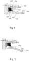
- a first GAS mounting possibility is shown.
- the sensor is attached to the accelerator pedal arm 200 on the upper side 207.
- the human engineering and the functioning of the accelerator pedal remain unchanged.
- the driver's foot 202 actuates the accelerator pedal 201, tensing the spring 205 and pulling the carburetor cable 206.
- the movements of the accelerator pedal produce all the time an acceleration vector on the sensor 204.
- the acceleration vector causes a change in an electric parameter in acceleration sensor 204.
- a drop in the electric resistnce of the sensor occurs, while in the piezo-electric version an electric charge is produced by the piezo-electric element.
- threshold means are provided so that mere acceleration of the moving element positioned on the pedal, in any appropriate position, is not sufficient to generate a signal that will actuate the brake lights.
- stopper means are provided so that when the pedal reaches its final position it stops abruptly. Stopper means can be of any suitable type, as long as they are positioned so as to prevent upwards movement of the pedal beyond a predetermined position.
- the stopper means will typically be mechanical stopper means which physically stop the pedal, but any other suitable device can be employed, e.g., a stopper can be positioned on the accelerator cable, to limit its movement against the body of the vehicle. Only when such an abrupt change takes place, and the moving element of the inertial signal-generating means continues to move by a predetermined amount, then the signal will be generated.
- this quantity can be preset, according to different pedals and location of the pedal, so that the signal is generated always only when the pedal stops abruptly. For instance, if the pedal has almost reached its inertial position, evene if it is abruptly released for the remaining small fraction of its path, this would not cause the brake lights to be actuated. In this way, many false alarms can be avoided.
- the inertial signal-generating means is shown in Fig. 5.
- the housing is made of two parts:
- the housing 310 & 320 is attached to the accelerator pedal arm via attachment means 322 and 323.
- the movements of the accelerator pedal arm are being transmitted to the housing 320 & 310 and through the sensor support 321 to the FSR 330.
- the right side 331 of the sensor 330 is bending freely toward the basis 320 under its own inertia, when the acceleration pedal is released by the driver's foot, and abruptly stops.
- the bending of the sensor 330 causes electrical parameter changes in the sensor.
- the bending of the right end 331 produces a mechanical stress between the sheets 433 and 434 (Fig. 5B). This stress causes the electrical resistance of FSR to drop.
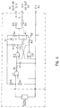
- the electronic circuit Fig. 4
- a piezo-electric element is used.
- the right side 331 of the sensor 330 is made of materials like plastic, ceramic or other, and bends freely when the housing 310 comes to a halt.
- the basis 320 has two supports 321 supporting both ends 331 and 332 firmly in place while the middle of the sensor 330 can bend freely toward the basis 320.
- Still another embodiment can be envisioned by those skilled in the art where the sensor is of round shape and held in place by the edges, while the middle of the sensor bends freely toward the basis, under the influence of the acceleration vector.
- the housing 320 and 310 of the sensor 204 is made of a rigid material, for example, metal or plastic.
- the housing has the means to accommodate the moving element 330, and to allow it to bend freely in order to provide the change in its electrical parameters.
- the housing is provided with suitable openings and fasteners to let the wires 351 & 352 exit, and to fasten the ends of the wires to the housing.
- a typical Force Sensing Resistor is shown in Fig. 5B, and is based on two polymer films or sheets.
- a conducting pattern is deposited on the polymer sheet 434 in the form of a set of interdigiting fingers.
- the finger pattern is typically on the order of 8.4 mm finger width and spacing, but other spacings can be used, as well.
- a conductive polymer is deposited on the other sheet, 433. The sheets are facing together so that the conducting fingers are shunted by the conductive polymer.
- the resistor is connected to the electric wires 351 and 352 of sensor 204 (Fig. 5A), via connections 351' and 352'.
- a sensor is constructed according to another preferred embodiment of the invention.
- the moving element 334 is provided with a weight 335, which has the purpose of increasing its inertia and to assist in causing it to bend.
- the weight can be constructed as an integral part of the moving element, e.g. if the moving element is made of plastic material or of cast material in general, or can be attached to the moving element by any suitable means, e.g. by glueing.
- the moving element 334 is made of conductive material, and the electric wire 352 is thus connected to the moving element itself, which is in turn in electric contact with one end of, e.g., a signal generating element 400, which may be, e.g. a piezoelectric film or the resistor of Fig. 5B.
- Wire 351 is connected directly to the upper contact of element 400.
- the electric contacts between element 400 and wires 351 and 352 can be effected in any suitable way, e.g., by soldering, conductive glue, pins, spring contact, electric connectors or the like, as long as they ensure sufficient and reliable electric contact.
- the moving element 334 is held in place by its connection to the holder 336, which connection can be effected by a screw or the like connection, as illustrated in Fig. 5A, or by glueing or welding, or by any other suitable means, but moving element 334 can also be integral with holder 336 and can be, for instance, made of a single piece of cast plastic material.
- a signal-generating element 400 is provided which, again, may be a piezoelectric film or a device as shown in Fig.
- both electrodes of which are positioned on the upper side, so that both wires 351 and 352 are connected directly thereto.
- the moving element 334 is not required to be made of conductive material. It is also worth noting in this figure the blunt end 338 of the holder 336, which can conveniently be provided to insure proper installation of the device within its housing.
- Fig. 5E yet another preferred embodiment of the invention is illustrated, in which the body 337 comprises both the holder and the moving element which is integral with the holder. This is convenient when it is desired to manufcature the element 337 in one piece, e.g., by casting a plastic material.
- Fig. 6 shows the connection between GAS and the vehicle brake lights.
- the outputs 91 and 92 of the GAS are connected to the two wires of the vehicle brake lights 81 and 83.
- the electronic current of the GAS is built to accecpt either wires 91 and 92 connected to either wires 81 and 83 without polarity.
- a different connection between the GAS and the vehicle brake lights is shown, which is a 2-wire arrangement.
- the difference between the circuits of Fig. 6 and Fig. 7 is that in Fig. 7 an internal power supply is to be provided, since a small leakage current will always be present in the circuit.
- the advantage of having only two wires to be connected is considerable, because the installation work is reduced, and because it is normally difficult to locate the minus (-) wire in a motor car, and its connection to the vehicle is sometimes precarious.
- GAS sensor is indicated as GASS
- GAS arrangement is indicated as GAS and as GAS-C, in Figs. 6 and 7 respectively.
- FIGs. 3A, 3B, 3C, 3D and 3E different GAS mounting possibilities are shown. Due to its relatively small dimensions and its friendly design, the GAS 204 can be easily installed either on the acceleration pedal arm 200, Figs. A, B, C and D; or under the accelerator pedal 201 of Fig. 3E.
- the GAS is very simple, however, using the latest state of the art technology sensor, which is specially designed to adapt easily to most acceleration pedals known in the market.
- the GAS may be connected by the manufacturer of the vehicle at the time od manufacturing, or may easily be installed later by the purchaser. The installation requires no special tools.
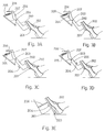
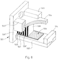
- Figs. 8-11 show an inertial signal-generating device.
- numeral 501 generally indicates the main body of the device according to the embodiment shown in the figures, to which there are connected a number of elements: the bendable basis 502, which may be integral with the main body 501, or may be connected thereto, in any appropriate way and supporting elements 503 and 503', for the roofing contact element 504, which will be discussed later.
- Stopper means 505 can be connected either to basis 502, or to main element 501, or to both.
- Elements 501, 502, 503, 503' and 505 can of course also be made of one piece, e.g., by casting or moulding of a plastic material.
- the bending sensor, 506 is made of a flat element onto which a film has been connected, which creates two electrodes, 507 and 507', which are both on the upper part of sensor 506.
- Sensor 506 is positioned in its correct position by providing stopper element 505, which limits its position with respect to the main body 501.
- a Zebra connector 508 is provided, which is in contact with both electrodes 507 and 507'. However, because of its nature, only elements 509 and 509' (Fig. 9) will be in contact with electrode 507, while only layers 510 and 510' will be in contact with electrode 507'. On the other side of connector 508, on roofing element 504, appropriate electric contacts will be positioned so as to be in contact with the appropriate section of connector 508 (not shown in fig. 9). This can be seen, e.g., in Fig.
- roofing element 504 which can be, e.g., a printed circuit board, is see, to be provided with two contacts, 511 and 511', which are in turn connected by electric connections (not shown) to electric wires 512 and 512', which lead the signal to the appropriate analyzing means.
- the electric contacts 511 and 511', as well as their electric connections to wires 512 and 512', can be embedded in roofing elements 504, or can be connected thereto and may be, e.g., strips of conducting materials, and the appropriate construction of these connections can be easily devised by the skilled engineer.
- roofing element 504 is connected to the device by sliding it into grooves 513 and 513' of elements 503 and 503', which will hold it in place in its assembled position.
- An addizional weight 514 is provided, according to this embodiment of the invention, to promote bending of basis 502, which weight can be of any suitable material, depending on the specific density required of this weight.
- the assembly of the inertial signal-generating device is effected as follows.
- the bending sensor 506 is positioned on bending basis 502, until it stops at stopper 505.
- Connection between the bending element 506 and bending basis 502 must be through and rigid, and can be effected, e.g. glueing.
- Zebra connector 508 is positioned on bending sensor 506, in juxtaposition with the inner wall 501' of wall element 501, and then roofing element 504 is caused to slide into grooves 513 and 513' of elements 503 and 503', simultaneusly applying a slight pressure on connector 508, so as to hold it tightly in place against bending sensor 506, and on electrodes 511 and 511' positioned on the said roofing element.
- weight element 514 if existing, can be assembled and can be kept in place by any convenient connecting element.
- wiring 515 is to be passed, according to this embodiment of the invention, through opening 516 in main body 501.
- the device according to this preferred embodiment of the invention is seen in its bending state, and it is seen that its extremity, bearing the weight 514, is bending more strongly than its whole body, but such bending is sufficient in order to cause a bending of bending sensor 506.
- the extent of bending can be important, or only the fact that some bending has taken place is sufficient to generate an appropriate signal.
- the shape of the various elements shown in the figures is not essential, and can be changed according to design requirements and production as well as economic considerations, and the skilled engineer will easily devise a large number of different elements, leading to different looking inertial signal-generating devices.
- an elastic connector such as a Zebra connector, which elastic connector is held tightly in place against the electrodes, to insure effective and reliable electric contact.
- Such Zebra connector will also be provided with insulating zones, as appropriate according to the specific use and shape of the electric contacts.
- the senor and the circuitry can be miniaturized and included in a single housing, or they may be separate from one another; different electronic and electric circuits can be provided, to fit into different housing and constructions of the device, all without exceeding the scope of the invention.
Applications Claiming Priority (6)
| Application Number | Priority Date | Filing Date | Title |
|---|---|---|---|
| IL9739791A IL97397A (en) | 1991-03-01 | 1991-03-01 | Early brakelight activating device in vehicle |
| IL97397 | 1991-03-01 | ||
| IL9983691A IL99836A (en) | 1991-03-01 | 1991-10-23 | Brake lights activation system |
| IL99836 | 1991-10-23 | ||
| IL100197 | 1991-11-29 | ||
| IL10019791A IL100197A (en) | 1991-11-29 | 1991-11-29 | Inertial signal-generating device |
Publications (2)
| Publication Number | Publication Date |
|---|---|
| EP0501555A1 true EP0501555A1 (de) | 1992-09-02 |
| EP0501555B1 EP0501555B1 (de) | 1997-12-17 |
Family
ID=27271493
Family Applications (1)
| Application Number | Title | Priority Date | Filing Date |
|---|---|---|---|
| EP92200430A Expired - Lifetime EP0501555B1 (de) | 1991-03-01 | 1992-02-15 | Ansteuerung der Bremsleuchten und Trägheitseinrichtung zur Signalerzeugung |
Country Status (9)
| Country | Link |
|---|---|
| US (1) | US5387898A (de) |
| EP (1) | EP0501555B1 (de) |
| JP (1) | JPH0769128A (de) |
| AT (1) | ATE161231T1 (de) |
| AU (1) | AU658166B2 (de) |
| CA (1) | CA2061419A1 (de) |
| DE (1) | DE69223532T2 (de) |
| ES (1) | ES2112295T3 (de) |
| GR (1) | GR3026101T3 (de) |
Cited By (6)
| Publication number | Priority date | Publication date | Assignee | Title |
|---|---|---|---|---|
| WO1994011221A1 (en) * | 1992-11-18 | 1994-05-26 | Geoffrey Miles Furness | Early warning brake light system |
| ES2064174A1 (es) * | 1991-04-02 | 1995-01-16 | Moreno Jose Fajardo | Avisador de señalizacion optica dirigido a la seguridad vial. |
| EP0890477A2 (de) | 1997-07-11 | 1999-01-13 | Volkswagen Aktiengesellschaft | Bremsvorwarnsystem |
| US6023221A (en) * | 1997-08-25 | 2000-02-08 | Michelotti; Paul E | System to activate automobile hazard warning lights |
| US6386023B1 (en) | 1999-03-24 | 2002-05-14 | Delphi Technologies, Inc. | Sensor for increasing signal response time |
| WO2008025082A1 (en) * | 2006-09-01 | 2008-03-06 | Mark William Gallon | Braking display apparatus |
Families Citing this family (17)
| Publication number | Priority date | Publication date | Assignee | Title |
|---|---|---|---|---|
| US5534672A (en) * | 1995-02-06 | 1996-07-09 | Emerson Electric Co. | Multiple plunger pedal switch assembly |
| US5942972A (en) * | 1995-04-06 | 1999-08-24 | Baran Advanced Technologies | Early lighting of brake-lights in vehicles |
| US5835008A (en) * | 1995-11-28 | 1998-11-10 | Colemere, Jr.; Dale M. | Driver, vehicle and traffic information system |
| CN2309249Y (zh) * | 1997-08-27 | 1999-03-03 | 杨士朋 | 机动车防追尾刹车灯超前示警装置 |
| DE19814574B4 (de) * | 1998-04-01 | 2005-03-10 | Bosch Gmbh Robert | System zur Erzeugung eines Signals zur Ansteuerung der Bremsleuchten eines Kraftfahrzeugs |
| US6054919A (en) * | 1998-07-16 | 2000-04-25 | Demko; Paul S. | Advanced braking light system |
| US6294985B1 (en) | 1998-09-28 | 2001-09-25 | Jeffery M. Simon | Remotely triggered collision avoidance strobe system |
| EP1125811B1 (de) * | 2000-02-19 | 2003-05-07 | Robert Bosch Gmbh | Verfahren und Vorrichtung zum Erkennen eines Bremsschalterfehlers |
| DE10024881A1 (de) * | 2000-05-19 | 2002-01-31 | Daimler Chrysler Ag | Verfahren und Vorrichtung zur Bremslichtansteuerung in Kraftfahrzeugen |
| US6677855B2 (en) | 2001-08-24 | 2004-01-13 | Ford Global Technologies, Llc | System to determine the intent to brake and to provide initiation and engagement of the brake system |
| US6919801B2 (en) * | 2003-10-06 | 2005-07-19 | Jae Yeal Kim | Vehicle safety system for preventing inadvertent acceleration of a vehicle |
| US20060158323A1 (en) * | 2004-12-04 | 2006-07-20 | Pattison Robert J | Vehicle warning system |
| WO2006107301A1 (en) * | 2005-04-05 | 2006-10-12 | Jae Yeal Kim | Vehicle safety system for preventing inadvertent acceleration of a vehicle |
| US20070008095A1 (en) * | 2005-06-09 | 2007-01-11 | Gwinn H S M | Intelligent brake light system |
| GB2465387A (en) * | 2008-11-14 | 2010-05-19 | Wan Jee Co Ltd | Brake light activation to indicate engine braking by monitoring accelerator pedal |
| JP5591067B2 (ja) * | 2010-11-02 | 2014-09-17 | 株式会社小糸製作所 | 車両用灯具の制御装置、車両用灯具システム、および車両用灯具の制御方法 |
| WO2013115686A1 (en) | 2012-02-02 | 2013-08-08 | Volvo Construction Equipment Ab | A method for actuating a brake light of a hydraulic driven working machine |
Citations (4)
| Publication number | Priority date | Publication date | Assignee | Title |
|---|---|---|---|---|
| DE1945867A1 (de) * | 1968-09-11 | 1970-04-23 | Sattler Gernot | Einrichtung zur Anzeige einer Schnellbremsung eines Fahrzeuges |
| US3659260A (en) * | 1970-09-30 | 1972-04-25 | Joseph A St Pierre | Vehicle warning light device |
| DE2544695A1 (de) * | 1975-02-24 | 1976-09-02 | Univ Dresden Tech | Schaltungsanordnung zur einschaltung von bremslicht und bremse fuer fahrzeuge |
| EP0360167A2 (de) * | 1988-09-20 | 1990-03-28 | Makash - Advanced Piezo Technology | Warnungsverzögerungspiezosensor für Fahrzeuge |
Family Cites Families (6)
| Publication number | Priority date | Publication date | Assignee | Title |
|---|---|---|---|---|
| US3501742A (en) * | 1966-08-11 | 1970-03-17 | Lynn E Ellison | Deceleration signalling system for motor vehicles |
| GB1436227A (en) * | 1973-06-18 | 1976-05-19 | Bryant E A | Deceleration and stop-light signalling means for motor cars and other vehicles |
| JPS5984639A (ja) * | 1982-11-06 | 1984-05-16 | Yukio Sato | 減速感知機能を有するストツプランプ点灯装置 |
| JPS6167643A (ja) * | 1984-09-07 | 1986-04-07 | Norihiro Yoshitome | 自動車の減速表示装置法 |
| GB8519026D0 (en) * | 1985-07-27 | 1985-09-04 | Laing J | Piezo electrical inertia sensitive device |
| US4916431A (en) * | 1988-01-29 | 1990-04-10 | John Gearey | Early warning indicator for a braking system |
-
1992
- 1992-02-15 EP EP92200430A patent/EP0501555B1/de not_active Expired - Lifetime
- 1992-02-15 DE DE69223532T patent/DE69223532T2/de not_active Expired - Fee Related
- 1992-02-15 AT AT92200430T patent/ATE161231T1/de not_active IP Right Cessation
- 1992-02-15 ES ES92200430T patent/ES2112295T3/es not_active Expired - Lifetime
- 1992-02-17 AU AU11013/92A patent/AU658166B2/en not_active Ceased
- 1992-02-18 JP JP3103292A patent/JPH0769128A/ja active Pending
- 1992-02-18 US US07/837,330 patent/US5387898A/en not_active Expired - Fee Related
- 1992-02-18 CA CA002061419A patent/CA2061419A1/en not_active Abandoned
-
1998
- 1998-02-12 GR GR980400269T patent/GR3026101T3/el unknown
Patent Citations (4)
| Publication number | Priority date | Publication date | Assignee | Title |
|---|---|---|---|---|
| DE1945867A1 (de) * | 1968-09-11 | 1970-04-23 | Sattler Gernot | Einrichtung zur Anzeige einer Schnellbremsung eines Fahrzeuges |
| US3659260A (en) * | 1970-09-30 | 1972-04-25 | Joseph A St Pierre | Vehicle warning light device |
| DE2544695A1 (de) * | 1975-02-24 | 1976-09-02 | Univ Dresden Tech | Schaltungsanordnung zur einschaltung von bremslicht und bremse fuer fahrzeuge |
| EP0360167A2 (de) * | 1988-09-20 | 1990-03-28 | Makash - Advanced Piezo Technology | Warnungsverzögerungspiezosensor für Fahrzeuge |
Cited By (10)
| Publication number | Priority date | Publication date | Assignee | Title |
|---|---|---|---|---|
| ES2064174A1 (es) * | 1991-04-02 | 1995-01-16 | Moreno Jose Fajardo | Avisador de señalizacion optica dirigido a la seguridad vial. |
| WO1994011221A1 (en) * | 1992-11-18 | 1994-05-26 | Geoffrey Miles Furness | Early warning brake light system |
| US5589817A (en) * | 1992-11-18 | 1996-12-31 | Furness; Geoffrey M. | Early warning brake light system |
| EP0890477A2 (de) | 1997-07-11 | 1999-01-13 | Volkswagen Aktiengesellschaft | Bremsvorwarnsystem |
| DE19729853C2 (de) * | 1997-07-11 | 2003-12-11 | Volkswagen Ag | Bremsvorwarnsystem |
| US6023221A (en) * | 1997-08-25 | 2000-02-08 | Michelotti; Paul E | System to activate automobile hazard warning lights |
| US6386023B1 (en) | 1999-03-24 | 2002-05-14 | Delphi Technologies, Inc. | Sensor for increasing signal response time |
| WO2008025082A1 (en) * | 2006-09-01 | 2008-03-06 | Mark William Gallon | Braking display apparatus |
| US8525661B2 (en) | 2006-09-01 | 2013-09-03 | Mark W. Gallon | Water vehicle braking display apparatus |
| AU2006211855B2 (en) * | 2006-09-01 | 2014-02-13 | Mark William Gallon | Braking Display Apparatus |
Also Published As
| Publication number | Publication date |
|---|---|
| AU658166B2 (en) | 1995-04-06 |
| GR3026101T3 (en) | 1998-05-29 |
| CA2061419A1 (en) | 1992-09-02 |
| DE69223532T2 (de) | 1998-06-04 |
| US5387898A (en) | 1995-02-07 |
| DE69223532D1 (de) | 1998-01-29 |
| ES2112295T3 (es) | 1998-04-01 |
| EP0501555B1 (de) | 1997-12-17 |
| JPH0769128A (ja) | 1995-03-14 |
| AU1101392A (en) | 1992-09-03 |
| ATE161231T1 (de) | 1998-01-15 |
Similar Documents
| Publication | Publication Date | Title |
|---|---|---|
| EP0501555B1 (de) | Ansteuerung der Bremsleuchten und Trägheitseinrichtung zur Signalerzeugung | |
| EP0360167B1 (de) | Warnungsverzögerungspiezosensor für Fahrzeuge | |
| KR100289199B1 (ko) | 차량 안전유지 시스템의 충돌센서 | |
| US4009619A (en) | Accelerometers | |
| EP1231623B1 (de) | Wetterfeste Schaltvorrichtung | |
| US4034338A (en) | Operating condition signal light for an automotive vehicle | |
| US20080093205A1 (en) | Buckle switching device for safety belts | |
| US5210522A (en) | Early warning brake light actuated by the accelerator pedal | |
| JP2009123480A (ja) | スイッチ及びこれを用いたスイッチ装置 | |
| KR970069577A (ko) | 전자플래셔장치 | |
| EP0390363A1 (de) | Fernsteuerungshebelmodul | |
| US7170402B2 (en) | Automatic braking light | |
| US4825696A (en) | Acceleration detector | |
| US6184764B1 (en) | Pendulum mass acceleration sensor | |
| WO2005026861A3 (de) | Pedal-vorrichtung für kraftfahrzeuge | |
| JP4351899B2 (ja) | 車載用電子機器 | |
| WO2022192850A1 (en) | Brake light for bicycles | |
| IL100197A (en) | Inertial signal-generating device | |
| US6610940B2 (en) | Mechanical acceleration sensor | |
| KR200178026Y1 (ko) | 자석을 이용한 비접촉식 연료량 표시장치 | |
| WO2010114812A1 (en) | Restraint system including a disengaged coupling apparatus indicator | |
| US20240101027A1 (en) | Acoustic warning device for a vehicle steering wheel | |
| JP2023153061A (ja) | ブレーキアクセルペダル変位検知表示装置 | |
| RU5561U1 (ru) | Сигнализатор системы безопасности автомобиля | |
| JPS6339454B2 (de) |
Legal Events
| Date | Code | Title | Description |
|---|---|---|---|
| PUAI | Public reference made under article 153(3) epc to a published international application that has entered the european phase |
Free format text: ORIGINAL CODE: 0009012 |
|
| AK | Designated contracting states |
Kind code of ref document: A1 Designated state(s): AT BE CH DE DK ES FR GB GR IT LI LU MC NL PT SE |
|
| 17P | Request for examination filed |
Effective date: 19930219 |
|
| K1C1 | Correction of patent application (title page) published |
Effective date: 19920902 |
|
| 17Q | First examination report despatched |
Effective date: 19960502 |
|
| GRAG | Despatch of communication of intention to grant |
Free format text: ORIGINAL CODE: EPIDOS AGRA |
|
| GRAG | Despatch of communication of intention to grant |
Free format text: ORIGINAL CODE: EPIDOS AGRA |
|
| GRAH | Despatch of communication of intention to grant a patent |
Free format text: ORIGINAL CODE: EPIDOS IGRA |
|
| GRAH | Despatch of communication of intention to grant a patent |
Free format text: ORIGINAL CODE: EPIDOS IGRA |
|
| GRAA | (expected) grant |
Free format text: ORIGINAL CODE: 0009210 |
|
| AK | Designated contracting states |
Kind code of ref document: B1 Designated state(s): AT BE CH DE DK ES FR GB GR IT LI LU MC NL PT SE |
|
| PG25 | Lapsed in a contracting state [announced via postgrant information from national office to epo] |
Ref country code: NL Free format text: LAPSE BECAUSE OF FAILURE TO SUBMIT A TRANSLATION OF THE DESCRIPTION OR TO PAY THE FEE WITHIN THE PRESCRIBED TIME-LIMIT Effective date: 19971217 Ref country code: LI Free format text: LAPSE BECAUSE OF FAILURE TO SUBMIT A TRANSLATION OF THE DESCRIPTION OR TO PAY THE FEE WITHIN THE PRESCRIBED TIME-LIMIT Effective date: 19971217 Ref country code: DK Free format text: LAPSE BECAUSE OF NON-PAYMENT OF DUE FEES Effective date: 19971217 Ref country code: CH Free format text: LAPSE BECAUSE OF FAILURE TO SUBMIT A TRANSLATION OF THE DESCRIPTION OR TO PAY THE FEE WITHIN THE PRESCRIBED TIME-LIMIT Effective date: 19971217 Ref country code: BE Free format text: LAPSE BECAUSE OF FAILURE TO SUBMIT A TRANSLATION OF THE DESCRIPTION OR TO PAY THE FEE WITHIN THE PRESCRIBED TIME-LIMIT Effective date: 19971217 Ref country code: AT Free format text: LAPSE BECAUSE OF FAILURE TO SUBMIT A TRANSLATION OF THE DESCRIPTION OR TO PAY THE FEE WITHIN THE PRESCRIBED TIME-LIMIT Effective date: 19971217 |
|
| REF | Corresponds to: |
Ref document number: 161231 Country of ref document: AT Date of ref document: 19980115 Kind code of ref document: T |
|
| REG | Reference to a national code |
Ref country code: CH Ref legal event code: EP |
|
| REF | Corresponds to: |
Ref document number: 69223532 Country of ref document: DE Date of ref document: 19980129 |
|
| PG25 | Lapsed in a contracting state [announced via postgrant information from national office to epo] |
Ref country code: LU Free format text: LAPSE BECAUSE OF NON-PAYMENT OF DUE FEES Effective date: 19980215 |
|
| ITF | It: translation for a ep patent filed |
Owner name: DRAGOTTI & ASSOCIATI S.R.L. |
|
| PG25 | Lapsed in a contracting state [announced via postgrant information from national office to epo] |
Ref country code: SE Free format text: LAPSE BECAUSE OF FAILURE TO SUBMIT A TRANSLATION OF THE DESCRIPTION OR TO PAY THE FEE WITHIN THE PRESCRIBED TIME-LIMIT Effective date: 19980317 |
|
| REG | Reference to a national code |
Ref country code: ES Ref legal event code: FG2A Ref document number: 2112295 Country of ref document: ES Kind code of ref document: T3 |
|
| ET | Fr: translation filed | ||
| REG | Reference to a national code |
Ref country code: PT Ref legal event code: SC4A Free format text: AVAILABILITY OF NATIONAL TRANSLATION Effective date: 19980219 |
|
| NLV1 | Nl: lapsed or annulled due to failure to fulfill the requirements of art. 29p and 29m of the patents act | ||
| REG | Reference to a national code |
Ref country code: CH Ref legal event code: PL |
|
| PG25 | Lapsed in a contracting state [announced via postgrant information from national office to epo] |
Ref country code: MC Free format text: LAPSE BECAUSE OF NON-PAYMENT OF DUE FEES Effective date: 19980831 |
|
| PLBE | No opposition filed within time limit |
Free format text: ORIGINAL CODE: 0009261 |
|
| STAA | Information on the status of an ep patent application or granted ep patent |
Free format text: STATUS: NO OPPOSITION FILED WITHIN TIME LIMIT |
|
| 26N | No opposition filed | ||
| PGFP | Annual fee paid to national office [announced via postgrant information from national office to epo] |
Ref country code: GB Payment date: 19990216 Year of fee payment: 8 |
|
| PGFP | Annual fee paid to national office [announced via postgrant information from national office to epo] |
Ref country code: PT Payment date: 19990219 Year of fee payment: 8 Ref country code: ES Payment date: 19990219 Year of fee payment: 8 |
|
| PGFP | Annual fee paid to national office [announced via postgrant information from national office to epo] |
Ref country code: GR Payment date: 19990226 Year of fee payment: 8 Ref country code: FR Payment date: 19990226 Year of fee payment: 8 |
|
| PGFP | Annual fee paid to national office [announced via postgrant information from national office to epo] |
Ref country code: DE Payment date: 19990315 Year of fee payment: 8 |
|
| PG25 | Lapsed in a contracting state [announced via postgrant information from national office to epo] |
Ref country code: GB Free format text: LAPSE BECAUSE OF NON-PAYMENT OF DUE FEES Effective date: 20000215 |
|
| PG25 | Lapsed in a contracting state [announced via postgrant information from national office to epo] |
Ref country code: ES Free format text: LAPSE BECAUSE OF NON-PAYMENT OF DUE FEES Effective date: 20000216 |
|
| PG25 | Lapsed in a contracting state [announced via postgrant information from national office to epo] |
Ref country code: GR Free format text: LAPSE BECAUSE OF NON-PAYMENT OF DUE FEES Effective date: 20000229 |
|
| PG25 | Lapsed in a contracting state [announced via postgrant information from national office to epo] |
Ref country code: PT Free format text: LAPSE BECAUSE OF NON-PAYMENT OF DUE FEES Effective date: 20000831 |
|
| GBPC | Gb: european patent ceased through non-payment of renewal fee |
Effective date: 20000215 |
|
| PG25 | Lapsed in a contracting state [announced via postgrant information from national office to epo] |
Ref country code: FR Free format text: LAPSE BECAUSE OF NON-PAYMENT OF DUE FEES Effective date: 20001031 |
|
| PG25 | Lapsed in a contracting state [announced via postgrant information from national office to epo] |
Ref country code: DE Free format text: LAPSE BECAUSE OF NON-PAYMENT OF DUE FEES Effective date: 20001201 |
|
| REG | Reference to a national code |
Ref country code: FR Ref legal event code: ST |
|
| REG | Reference to a national code |
Ref country code: PT Ref legal event code: MM4A Free format text: LAPSE DUE TO NON-PAYMENT OF FEES Effective date: 20000831 |
|
| REG | Reference to a national code |
Ref country code: ES Ref legal event code: FD2A Effective date: 20010910 |
|
| PG25 | Lapsed in a contracting state [announced via postgrant information from national office to epo] |
Ref country code: IT Free format text: LAPSE BECAUSE OF NON-PAYMENT OF DUE FEES;WARNING: LAPSES OF ITALIAN PATENTS WITH EFFECTIVE DATE BEFORE 2007 MAY HAVE OCCURRED AT ANY TIME BEFORE 2007. THE CORRECT EFFECTIVE DATE MAY BE DIFFERENT FROM THE ONE RECORDED. Effective date: 20050215 |