EP0501140A1 - Echafaudage de montage déplaçable dans une cage d'ascenseur pour monter l'équipement de cage - Google Patents
Echafaudage de montage déplaçable dans une cage d'ascenseur pour monter l'équipement de cage Download PDFInfo
- Publication number
- EP0501140A1 EP0501140A1 EP92101056A EP92101056A EP0501140A1 EP 0501140 A1 EP0501140 A1 EP 0501140A1 EP 92101056 A EP92101056 A EP 92101056A EP 92101056 A EP92101056 A EP 92101056A EP 0501140 A1 EP0501140 A1 EP 0501140A1
- Authority
- EP
- European Patent Office
- Prior art keywords
- assembly scaffold
- scaffold according
- shaft
- movable assembly
- working
- Prior art date
- Legal status (The legal status is an assumption and is not a legal conclusion. Google has not performed a legal analysis and makes no representation as to the accuracy of the status listed.)
- Granted
Links
- 239000000725 suspension Substances 0.000 claims abstract description 10
- 239000000463 material Substances 0.000 claims abstract description 3
- 235000000396 iron Nutrition 0.000 claims description 2
- 230000004888 barrier function Effects 0.000 abstract description 2
- 241001131688 Coracias garrulus Species 0.000 description 11
- 238000000034 method Methods 0.000 description 3
- XEEYBQQBJWHFJM-UHFFFAOYSA-N Iron Chemical compound [Fe] XEEYBQQBJWHFJM-UHFFFAOYSA-N 0.000 description 2
- 230000000284 resting effect Effects 0.000 description 2
- 229910000831 Steel Inorganic materials 0.000 description 1
- 230000009194 climbing Effects 0.000 description 1
- 238000010276 construction Methods 0.000 description 1
- 238000010616 electrical installation Methods 0.000 description 1
- 229910052742 iron Inorganic materials 0.000 description 1
- 230000001681 protective effect Effects 0.000 description 1
- 239000010959 steel Substances 0.000 description 1
Images

Classifications
-
- B—PERFORMING OPERATIONS; TRANSPORTING
- B66—HOISTING; LIFTING; HAULING
- B66B—ELEVATORS; ESCALATORS OR MOVING WALKWAYS
- B66B19/00—Mining-hoist operation
Definitions
- the invention relates to a movable scaffolding in an elevator shaft for mounting shaft equipment, consisting of a hoist cable for the vertical lifting of a cabin support frame, on which working levels are arranged at the lower end and at the upper end.
- a disadvantage of the known device is that a mechanically complex yoke which is adaptable to the shaft cross section is necessary and must have means for resting on the upper edge of the shaft.
- Another A disadvantage of the known device is that the precise alignment of the guide rails is made more difficult by the suspended rail track.
- Another disadvantage is that the supporting frame serving as the work platform is already guided by the guide rails to be fastened and aligned, which in turn complicates the assembly work.
- the invention seeks to remedy this.
- the invention as characterized in the claims, solves the problem of avoiding the disadvantages of the known assembly method and the known device and of specifying a device for assembling shaft equipment with which extensive rationalization of the assembly work is possible, in particular with large delivery heights.
- the advantages achieved by the invention are essentially to be seen in the fact that different assembly work can be carried out at different levels at the same time, that the assembly work can be started even before the building is completed, which is particularly important in the case of climbing construction that the The support frame receiving the working planes is guided by means of already mounted and aligned guide rails and that the safety gear arranged on the support frame and interacting with the speed limiter can thus already be used as a safety device during the assembly work of the guide rails.
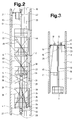
- 1 to 6, 1 designates an elevator shaft, which extends over several floors 2 and is comprised of shaft walls 3, in which an assembly scaffold with a first working level 4, with a second working level 5, with a third working level 6 and with for mounting shaft equipment a fourth working level 7 is moved in the vertical direction.
- the first working level 4 is arranged at the lower end and the second working level 5 at the upper end of a car support frame 8, which is provided for receiving the elevator car after the assembly work. Above the support frame 8, the mounting frame continues with the third working level 6 and ends with the fourth working level 7.
- a suspension tube 9, a lower deflection roller 10 arranged at the upper end of the suspension tube 9 and one arranged on a shaft support 11 serve as suspension of the support frame 8 upper pulley 12, which are connected via a 3: 1 suspended cable 13 of a lifting cable 14 anchored to the supporting frame 8. 15 denotes the fixed cable point on the upper deflection roller 12.
- the shaft support 11 resting on support angles 16 arranged in the elevator shaft 1 carries a speed limiter 17 and a cable pull with cable drum 18 and is covered by a protective structure 19.
- the cable with cable drum 18 serves as shown in Fig. 1 for the material transport.
- a cable 20 is diverted to the working point via a jib crane 21 arranged at the upper end of the suspension tube 9.
- the working levels 4; accessible via ladders 22 and access hatches 23; 5; 6; 7 are secured with railings 24 and folding barriers, not shown.
- Fig. 1 shows how on the third and fourth working level 6; 7 counterweight guide rails 25 are mounted. It is not shown how parts of manhole covers are assembled and electrical installations are carried out simultaneously from all working levels.
- the cabin support frame 8 is guided by means of an upper roller guide 26 and a lower roller guide 27 along a cabin guide rail 28 which extends beyond the second working level 5.
- a rail limit switch (not shown) with a switch roller running on the end face of the rail, which actuates a work contact for controlling the hoisting cable 14. As soon as the switch roller leaves the rail, the hoist cable 14 switches off without the upper roller guide 26 being moved beyond the end of the rail.
- FIG. 2 shows the cabin support frame 8 consisting of hanging iron 29, a lower cross member 30 and an upper cross member 31 Limiter rope 33 of the speed limiter 17 together, excess speeds of the mounting frame in the downward direction being avoided.
- Beams 34, a floor 35 with railings 24 and struts 36 made of flat steel, applied to the lower crossbeam 30 form the first working level 4.
- Corner post angles 37 are mounted on end plates, not shown, of the beams 34, which the upper working levels 5; 6; 7 wear.
- Tensioning ropes 38 and bandages 39 are provided for bracing the assembly scaffold.
- a lower part 40 of the hanging tube 9, which is provided with a fork-shaped end, is connected to the upper crossbar 31 via an intermediate piece (not shown).
- crane screwing plates 42 and the lower deflection roller 10 are arranged. With 46 already installed landing doors are designated.
- a first arm 43 is hinged at one end to the crane screw plates 42.
- a second arm 44 is articulated, which carries at the outer end a crane pulley 45 which derives the cable 20.
- Locking bolts (not shown) are provided on the joints for different working positions.
- the jib crane 21 is dimensioned so that all fixing points of the guide rails can be reached.
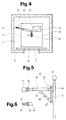
- FIGS. 5 and 6 show a telescopic boom 47 as a further embodiment variant of the jib crane 21, which is arranged on the hanging tube 9 at the working height of the uppermost working level 7.
- a telescopic arm 48 is articulated at one end to a support 49 arranged on the hanging tube 9.
- the telescopic arm 48 is supported by a hydraulic jack 50 acting on the lower end of the support 49.
- a holder 51 is articulated, on which, for example, the guide rail 25 to be mounted is clamped in the center.
- pivot points are referred to, at which the telescopic arm 48, support 49, hydraulic jack 50 and holder 51 are articulated together. Furthermore, an arrangement of the support 49 on the shaft door side is provided.
- guide rails are pulled up to a few centimeters above the assembly height by means of a cable 18 and then clamped to the holder 51.
- the telescopic arm 48 is then lowered by means of a hydraulic jack 50 until the guide rail has reached its end position. After the butt plate and fastening bracket have been screwed on, the assembled guide rail is detached from the holder 51 and cable 20.
- hanging irons stabilized by bandage pieces and extending over the entire height of the assembly frame are provided, which are connected by means of a lower cross member and an upper cross member.
- the lower roller guide and the safety gear are mounted on the lower crossbar and the upper roller guide is mounted on an intermediate crossbar at the height of the supporting frame.
- the jib crane and two rope pulleys are arranged on the upper crossbar.
- the mounting frame, which is independent of the cabin support frame, is suspended in a 4: 1 ratio.
Landscapes
- Movable Scaffolding (AREA)
- Lift-Guide Devices, And Elevator Ropes And Cables (AREA)
- Types And Forms Of Lifts (AREA)
- Jib Cranes (AREA)
- Load-Engaging Elements For Cranes (AREA)
- Micro-Organisms Or Cultivation Processes Thereof (AREA)
- Cage And Drive Apparatuses For Elevators (AREA)
- Ladders (AREA)
Applications Claiming Priority (2)
| Application Number | Priority Date | Filing Date | Title |
|---|---|---|---|
| CH629/91 | 1991-03-01 | ||
| CH62991 | 1991-03-01 |
Publications (2)
| Publication Number | Publication Date |
|---|---|
| EP0501140A1 true EP0501140A1 (fr) | 1992-09-02 |
| EP0501140B1 EP0501140B1 (fr) | 1995-03-29 |
Family
ID=4191465
Family Applications (1)
| Application Number | Title | Priority Date | Filing Date |
|---|---|---|---|
| EP92101056A Expired - Lifetime EP0501140B1 (fr) | 1991-03-01 | 1992-01-23 | Echafaudage de montage déplaçable dans une cage d'ascenseur pour monter l'équipement de cage |
Country Status (10)
| Country | Link |
|---|---|
| US (1) | US5230404A (fr) |
| EP (1) | EP0501140B1 (fr) |
| JP (1) | JP3202055B2 (fr) |
| AT (1) | ATE120428T1 (fr) |
| CA (1) | CA2060812A1 (fr) |
| DE (1) | DE59201741D1 (fr) |
| ES (1) | ES2073192T3 (fr) |
| HK (1) | HK125996A (fr) |
| RU (1) | RU2124053C1 (fr) |
| ZA (1) | ZA92710B (fr) |
Cited By (3)
| Publication number | Priority date | Publication date | Assignee | Title |
|---|---|---|---|---|
| CN110785370A (zh) * | 2017-06-26 | 2020-02-11 | 因温特奥股份公司 | 升降机设备 |
| CN111255217A (zh) * | 2020-03-27 | 2020-06-09 | 中建二局第二建筑工程有限公司 | 一种电梯井定型化操作平台及其作业方法 |
| CN111648588A (zh) * | 2020-07-03 | 2020-09-11 | 东莞兴成超越实业有限公司 | 一种电梯工装工作平台 |
Families Citing this family (44)
| Publication number | Priority date | Publication date | Assignee | Title |
|---|---|---|---|---|
| US5553686A (en) * | 1994-12-13 | 1996-09-10 | Otis Elevator Company | Installation of elevator rails in a hoistway |
| WO1998029325A1 (fr) * | 1996-12-31 | 1998-07-09 | Lee, David, Woon | Procede d'installation d'un cable d'ascenseur et d'un rail |
| CN1102908C (zh) | 1997-03-07 | 2003-03-12 | 通力股份公司 | 用于装设电梯的竖井设备的方法和设备 |
| FI109291B (fi) * | 1997-03-07 | 2002-06-28 | Kone Corp | Menetelmä ja laitteisto hissin asentamiseksi |
| SG108300A1 (en) * | 2001-06-27 | 2005-01-28 | Inventio Ag | Installing frame for installation of shaft equipment, installing lift with installing frame and method of installation of shaft equipment |
| US6668980B2 (en) * | 2001-07-06 | 2003-12-30 | Thyssen Elevator Capital Corp. | Elevator car isolation system and method |
| US20040154870A1 (en) * | 2003-01-28 | 2004-08-12 | Patrick Bass | Self-climbing elevator machine comprising a punched rail assembly |
| CN100564225C (zh) * | 2003-09-29 | 2009-12-02 | 奥蒂斯电梯公司 | 用于安装尤其是无任何机房的电梯的轿厢驱动机器的方法,以及所获得的电梯 |
| JP2008529933A (ja) * | 2005-02-18 | 2008-08-07 | オーチス エレベータ カンパニー | 全側面を同時に操作するハンドルを使って折り畳むことができるエレベータかご室天板柵 |
| US20090097952A1 (en) * | 2005-08-30 | 2009-04-16 | Otis Elevator Company | Method and device for transporting an elevator car drive machine |
| US8291568B2 (en) * | 2008-11-28 | 2012-10-23 | Kone Corporation | Method of installing an elevator |
| US8141683B1 (en) | 2009-04-30 | 2012-03-27 | Wurtec Elevator Products & Services | Expandable platform |
| FI121666B (fi) * | 2009-05-28 | 2011-02-28 | Kone Corp | Menetelmä hissin nostoköysistön asentamiseksi |
| WO2011052053A1 (fr) * | 2009-10-28 | 2011-05-05 | 三菱電機株式会社 | Dispositif d'arrêt d'urgence pour ascenseurs |
| CN102080446B (zh) * | 2011-02-18 | 2012-04-18 | 中国水利水电第七工程局成都水电建设工程有限公司 | 一种竖井施工升降平台 |
| CN102849562B (zh) * | 2011-06-30 | 2015-09-02 | 五冶集团上海有限公司 | 一种提高电梯筒内部井架安装精度的方法 |
| CN102817553A (zh) * | 2012-08-31 | 2012-12-12 | 江苏振东港口机械制造有限公司 | 一种起重机梯子栏杆系统 |
| EP2746210A1 (fr) * | 2012-12-19 | 2014-06-25 | Inventio AG | Procédé d'installation pour un ascenseur |
| EP2746211A1 (fr) * | 2012-12-19 | 2014-06-25 | Inventio AG | Procédé d'entretien pour un ascenseur |
| JP5798138B2 (ja) * | 2013-02-06 | 2015-10-21 | 信和株式会社 | 資材搬送リフト |
| EP3107856B1 (fr) * | 2014-02-21 | 2020-04-22 | Wurtec Elevator Products & Services | Dispositif de cabine provisoire |
| US10024488B2 (en) * | 2014-10-06 | 2018-07-17 | Wurtec, Incorporated | Three-beam construction apparatus |
| DK3032097T3 (en) * | 2014-12-11 | 2017-12-04 | Siemens Ag | Wind turbine tower with a lift system |
| CN104528500B (zh) * | 2014-12-29 | 2019-05-14 | 中国建筑股份有限公司 | 双平台无脚手架电梯安装方法 |
| CN107207208B (zh) * | 2015-02-05 | 2020-05-15 | 奥的斯电梯公司 | 用于电梯系统安装的交通工具和方法 |
| US10053874B2 (en) | 2015-02-18 | 2018-08-21 | Tarsco Construction Corporation | Adjustable scaffolding |
| EP3093262B1 (fr) * | 2015-05-12 | 2018-10-31 | KONE Corporation | Dispositif et procédé de transport parallèle et installation de composants d'ascenseur |
| CN104973515B (zh) * | 2015-07-05 | 2017-03-08 | 范志甫 | 一种起重机多节安全操作室及其操作方法 |
| CN105952132A (zh) * | 2016-06-20 | 2016-09-21 | 北京天润建设有限公司 | 一种电梯井提升平台 |
| US20180237269A1 (en) * | 2017-02-17 | 2018-08-23 | Otis Elevator Company | Ropeless elevator system modular installation |
| CN107724661B (zh) * | 2017-05-05 | 2020-02-14 | 民族建设集团有限公司 | 一种剪力墙井道结构施工可吊移式自动升降平台 |
| EP3412618B1 (fr) * | 2017-06-09 | 2020-12-30 | KONE Corporation | Procédé |
| CN107178203A (zh) * | 2017-06-29 | 2017-09-19 | 中铁十六局集团城市建设发展有限公司 | 一种平面尺寸及高度可调的操作平台 |
| JP3216078U (ja) * | 2018-02-21 | 2018-05-10 | 株式会社Pgs | メモリカード |
| CN108756194B (zh) * | 2018-08-03 | 2023-07-21 | 宁波北理汽车科技股份有限公司 | 一种用于安装电梯井道框架的伸缩式脚手架及其方法 |
| CN109972813A (zh) * | 2019-04-29 | 2019-07-05 | 北京天恒建设集团有限公司 | 一种电梯井内集成式整体施工平台系统 |
| EP3766819B1 (fr) * | 2019-07-16 | 2023-06-07 | KONE Corporation | Procédé et agencement permettant d'installer des rails de guidage d'ascenseur dans une cage d'ascenseur |
| CN111661767A (zh) * | 2020-05-29 | 2020-09-15 | 许伟虎 | 一种加固型建筑用吊装工具 |
| CN111822933A (zh) * | 2020-06-05 | 2020-10-27 | 中铁一局集团第五工程有限公司 | 钢筋笼分节连接加工平台 |
| CN112125238B (zh) * | 2020-08-05 | 2021-11-30 | 中石化宁波工程有限公司 | 一种竖井内钢梁的施工安装方法 |
| IT202100025607A1 (it) * | 2021-10-07 | 2023-04-07 | Fiorenzo Sartor | Montacarichi da cantiere e procedimento per la predisposizione di un montacarichi da cantiere |
| CN114197848B (zh) * | 2021-11-25 | 2023-04-07 | 中建八局第二建设有限公司 | 一种新型的电梯井道提升式斜撑操作钢平台 |
| CN114439213A (zh) * | 2021-12-23 | 2022-05-06 | 华北冶建工程建设有限公司 | 井道操作平台装置及其施工方法 |
| CN116201344A (zh) * | 2023-01-06 | 2023-06-02 | 华森天奥(重庆)机电有限公司 | 一种用于井道电梯钢结构安装的升降施工平台 |
Citations (3)
| Publication number | Priority date | Publication date | Assignee | Title |
|---|---|---|---|---|
| US3851736A (en) * | 1973-03-20 | 1974-12-03 | Westinghouse Electric Corp | Apparatus and method for installing elevator hoistway equipment |
| US4345671A (en) * | 1980-03-12 | 1982-08-24 | Westinghouse Electric Corp. | Apparatus and method for installing elevator guide rails |
| WO1989004807A1 (fr) * | 1987-11-27 | 1989-06-01 | Otis Elevator Company | Procede de montage d'un ascenseur ou monte-charge au sein d'un batiment, gabarits de montage utilises, ascenseur ou monte-charge obtenu |
Family Cites Families (2)
| Publication number | Priority date | Publication date | Assignee | Title |
|---|---|---|---|---|
| FR1495075A (fr) * | 1966-09-07 | 1967-09-15 | Kopalnia Wegla Kamiennego | Dispositif placé sous une cage d'extraction et permettant de descendre des étançons, rails et tubes de grande longueur dans un puits |
| US5065843A (en) * | 1990-05-16 | 1991-11-19 | Otis Elevator Company | Method for installing elevator system components |
-
1992
- 1992-01-23 DE DE59201741T patent/DE59201741D1/de not_active Expired - Fee Related
- 1992-01-23 ES ES92101056T patent/ES2073192T3/es not_active Expired - Lifetime
- 1992-01-23 EP EP92101056A patent/EP0501140B1/fr not_active Expired - Lifetime
- 1992-01-23 AT AT92101056T patent/ATE120428T1/de not_active IP Right Cessation
- 1992-01-31 ZA ZA92710A patent/ZA92710B/xx unknown
- 1992-02-11 CA CA002060812A patent/CA2060812A1/fr not_active Abandoned
- 1992-02-14 JP JP02844492A patent/JP3202055B2/ja not_active Expired - Fee Related
- 1992-02-28 US US07/843,150 patent/US5230404A/en not_active Expired - Fee Related
- 1992-02-28 RU SU5011329A patent/RU2124053C1/ru active
-
1996
- 1996-07-11 HK HK125996A patent/HK125996A/xx not_active IP Right Cessation
Patent Citations (3)
| Publication number | Priority date | Publication date | Assignee | Title |
|---|---|---|---|---|
| US3851736A (en) * | 1973-03-20 | 1974-12-03 | Westinghouse Electric Corp | Apparatus and method for installing elevator hoistway equipment |
| US4345671A (en) * | 1980-03-12 | 1982-08-24 | Westinghouse Electric Corp. | Apparatus and method for installing elevator guide rails |
| WO1989004807A1 (fr) * | 1987-11-27 | 1989-06-01 | Otis Elevator Company | Procede de montage d'un ascenseur ou monte-charge au sein d'un batiment, gabarits de montage utilises, ascenseur ou monte-charge obtenu |
Cited By (4)
| Publication number | Priority date | Publication date | Assignee | Title |
|---|---|---|---|---|
| CN110785370A (zh) * | 2017-06-26 | 2020-02-11 | 因温特奥股份公司 | 升降机设备 |
| CN110785370B (zh) * | 2017-06-26 | 2021-07-13 | 因温特奥股份公司 | 升降机设备 |
| CN111255217A (zh) * | 2020-03-27 | 2020-06-09 | 中建二局第二建筑工程有限公司 | 一种电梯井定型化操作平台及其作业方法 |
| CN111648588A (zh) * | 2020-07-03 | 2020-09-11 | 东莞兴成超越实业有限公司 | 一种电梯工装工作平台 |
Also Published As
| Publication number | Publication date |
|---|---|
| ES2073192T3 (es) | 1995-08-01 |
| ATE120428T1 (de) | 1995-04-15 |
| HK125996A (en) | 1996-07-19 |
| US5230404A (en) | 1993-07-27 |
| DE59201741D1 (de) | 1995-05-04 |
| EP0501140B1 (fr) | 1995-03-29 |
| RU2124053C1 (ru) | 1998-12-27 |
| ZA92710B (en) | 1992-10-28 |
| JPH04317977A (ja) | 1992-11-09 |
| JP3202055B2 (ja) | 2001-08-27 |
| CA2060812A1 (fr) | 1992-09-02 |
Similar Documents
| Publication | Publication Date | Title |
|---|---|---|
| EP0501140B1 (fr) | Echafaudage de montage déplaçable dans une cage d'ascenseur pour monter l'équipement de cage | |
| EP3548413B1 (fr) | Ascenseur et procédé d'installation d'un ascenseur | |
| DE68903630T2 (de) | Montageverfahren fuer einen aufzug und ein solcher aufzug. | |
| DE69107509T2 (de) | Arbeitsbühne eines Aufzugsschachts. | |
| DE69805257T2 (de) | Verfahren und apparatus zum einbau eines aufzugs | |
| EP1224142A1 (fr) | Monte-charge a cable | |
| EP4172096B1 (fr) | Procédé de construction d'une installation d'ascenseur et installation d'ascenseur | |
| DE102019205164A1 (de) | Verfahren zur Änderung der Förderhöhe einer Aufzuganlage mittels einer Gleitschalung | |
| EP0767134A2 (fr) | Système d'ascenseur et son procédé de montage | |
| EP4222097A1 (fr) | Système d'ascenseur | |
| EP0444307A1 (fr) | Scène descendante | |
| DE602004005796T2 (de) | Aufzug mit reduziertem Schachtkopf und Schachtgrube, sogar ohne Maschinenraum | |
| EP0384112B1 (fr) | Grue à tour, de préférence grue tournant au haut de la tour | |
| EP0626339A1 (fr) | Pont roulant comportant une construction pour plateforme de travail, en particulier pour la maintenance d'avions | |
| DE3526612A1 (de) | Brueckenseilinspektionsgeraet | |
| DE10154171A1 (de) | Modernisierung von Hydraulikaufzügen | |
| EP1245522A1 (fr) | Procédé de montage pour la machinerie dans une cage d'ascenseur | |
| DE4221915A1 (de) | Untendrehender Turmdrehkran | |
| DE3545965C2 (fr) | ||
| EP0152562A2 (fr) | Grue à tour télescopique | |
| EP0003982B2 (fr) | Echafaudage de façade pour murs en retrait | |
| DE19714848A1 (de) | Vorrichtung, welche sich, einschließlich eines angeschlossenen Personenaufnahmemittels, an zwei vorzugsweise parallel auseinander gelagerten Anhängetrumms, bestehend aus je einem Tragmittel und je einem Fangmittel, senkrecht oder geneigt auf und ab verlagert | |
| EP4406900A1 (fr) | Procédé de montage sans échafaudage d'une installation d'ascenseur dans une cage d'ascenseur | |
| EP2100843A1 (fr) | Grue dotée d'un tour télescopique | |
| DE19530704C1 (de) | Vorrichtung zur Lastaufnahme im Dachbereich von Gebäuden |
Legal Events
| Date | Code | Title | Description |
|---|---|---|---|
| PUAI | Public reference made under article 153(3) epc to a published international application that has entered the european phase |
Free format text: ORIGINAL CODE: 0009012 |
|
| AK | Designated contracting states |
Kind code of ref document: A1 Designated state(s): AT BE CH DE ES FR GB IT LI |
|
| 17P | Request for examination filed |
Effective date: 19930218 |
|
| 17Q | First examination report despatched |
Effective date: 19940616 |
|
| GRAA | (expected) grant |
Free format text: ORIGINAL CODE: 0009210 |
|
| AK | Designated contracting states |
Kind code of ref document: B1 Designated state(s): AT BE CH DE ES FR GB IT LI |
|
| REF | Corresponds to: |
Ref document number: 120428 Country of ref document: AT Date of ref document: 19950415 Kind code of ref document: T |
|
| REF | Corresponds to: |
Ref document number: 59201741 Country of ref document: DE Date of ref document: 19950504 |
|
| ET | Fr: translation filed | ||
| GBT | Gb: translation of ep patent filed (gb section 77(6)(a)/1977) |
Effective date: 19950428 |
|
| ITF | It: translation for a ep patent filed | ||
| REG | Reference to a national code |
Ref country code: ES Ref legal event code: FG2A Ref document number: 2073192 Country of ref document: ES Kind code of ref document: T3 |
|
| PGFP | Annual fee paid to national office [announced via postgrant information from national office to epo] |
Ref country code: BE Payment date: 19951229 Year of fee payment: 5 |
|
| PGFP | Annual fee paid to national office [announced via postgrant information from national office to epo] |
Ref country code: AT Payment date: 19960104 Year of fee payment: 5 |
|
| PGFP | Annual fee paid to national office [announced via postgrant information from national office to epo] |
Ref country code: ES Payment date: 19960112 Year of fee payment: 5 |
|
| PLBE | No opposition filed within time limit |
Free format text: ORIGINAL CODE: 0009261 |
|
| STAA | Information on the status of an ep patent application or granted ep patent |
Free format text: STATUS: NO OPPOSITION FILED WITHIN TIME LIMIT |
|
| 26N | No opposition filed | ||
| PGFP | Annual fee paid to national office [announced via postgrant information from national office to epo] |
Ref country code: CH Payment date: 19960418 Year of fee payment: 5 |
|
| PG25 | Lapsed in a contracting state [announced via postgrant information from national office to epo] |
Ref country code: AT Effective date: 19970123 |
|
| PG25 | Lapsed in a contracting state [announced via postgrant information from national office to epo] |
Ref country code: ES Free format text: LAPSE BECAUSE OF NON-PAYMENT OF DUE FEES Effective date: 19970124 |
|
| PG25 | Lapsed in a contracting state [announced via postgrant information from national office to epo] |
Ref country code: LI Effective date: 19970131 Ref country code: CH Effective date: 19970131 Ref country code: BE Effective date: 19970131 |
|
| BERE | Be: lapsed |
Owner name: INVENTIO A.G. Effective date: 19970131 |
|
| REG | Reference to a national code |
Ref country code: CH Ref legal event code: PL |
|
| REG | Reference to a national code |
Ref country code: ES Ref legal event code: FD2A Effective date: 19990201 |
|
| PGFP | Annual fee paid to national office [announced via postgrant information from national office to epo] |
Ref country code: GB Payment date: 19991213 Year of fee payment: 9 |
|
| PGFP | Annual fee paid to national office [announced via postgrant information from national office to epo] |
Ref country code: DE Payment date: 19991217 Year of fee payment: 9 |
|
| PGFP | Annual fee paid to national office [announced via postgrant information from national office to epo] |
Ref country code: FR Payment date: 19991221 Year of fee payment: 9 |
|
| PG25 | Lapsed in a contracting state [announced via postgrant information from national office to epo] |
Ref country code: GB Free format text: LAPSE BECAUSE OF NON-PAYMENT OF DUE FEES Effective date: 20010123 |
|
| GBPC | Gb: european patent ceased through non-payment of renewal fee |
Effective date: 20010123 |
|
| PG25 | Lapsed in a contracting state [announced via postgrant information from national office to epo] |
Ref country code: FR Free format text: LAPSE BECAUSE OF NON-PAYMENT OF DUE FEES Effective date: 20010928 |
|
| PG25 | Lapsed in a contracting state [announced via postgrant information from national office to epo] |
Ref country code: DE Free format text: LAPSE BECAUSE OF NON-PAYMENT OF DUE FEES Effective date: 20011101 |
|
| REG | Reference to a national code |
Ref country code: FR Ref legal event code: ST |
|
| PG25 | Lapsed in a contracting state [announced via postgrant information from national office to epo] |
Ref country code: IT Free format text: LAPSE BECAUSE OF NON-PAYMENT OF DUE FEES;WARNING: LAPSES OF ITALIAN PATENTS WITH EFFECTIVE DATE BEFORE 2007 MAY HAVE OCCURRED AT ANY TIME BEFORE 2007. THE CORRECT EFFECTIVE DATE MAY BE DIFFERENT FROM THE ONE RECORDED. Effective date: 20050123 |