EP0500196A2 - Modus und Gerät zur Vermeidung des Pumpens in einem dynamischen Verdichter - Google Patents
Modus und Gerät zur Vermeidung des Pumpens in einem dynamischen Verdichter Download PDFInfo
- Publication number
- EP0500196A2 EP0500196A2 EP19920201363 EP92201363A EP0500196A2 EP 0500196 A2 EP0500196 A2 EP 0500196A2 EP 19920201363 EP19920201363 EP 19920201363 EP 92201363 A EP92201363 A EP 92201363A EP 0500196 A2 EP0500196 A2 EP 0500196A2
- Authority
- EP
- European Patent Office
- Prior art keywords
- surge
- compressor
- surge limit
- operating point
- loop response
- Prior art date
- Legal status (The legal status is an assumption and is not a legal conclusion. Google has not performed a legal analysis and makes no representation as to the accuracy of the status listed.)
- Granted
Links
Images

Classifications
-
- F—MECHANICAL ENGINEERING; LIGHTING; HEATING; WEAPONS; BLASTING
- F04—POSITIVE - DISPLACEMENT MACHINES FOR LIQUIDS; PUMPS FOR LIQUIDS OR ELASTIC FLUIDS
- F04D—NON-POSITIVE-DISPLACEMENT PUMPS
- F04D27/00—Control, e.g. regulation, of pumps, pumping installations or pumping systems specially adapted for elastic fluids
- F04D27/02—Surge control
- F04D27/0284—Conjoint control of two or more different functions
-
- F—MECHANICAL ENGINEERING; LIGHTING; HEATING; WEAPONS; BLASTING
- F04—POSITIVE - DISPLACEMENT MACHINES FOR LIQUIDS; PUMPS FOR LIQUIDS OR ELASTIC FLUIDS
- F04D—NON-POSITIVE-DISPLACEMENT PUMPS
- F04D27/00—Control, e.g. regulation, of pumps, pumping installations or pumping systems specially adapted for elastic fluids
- F04D27/001—Testing thereof; Determination or simulation of flow characteristics; Stall or surge detection, e.g. condition monitoring
-
- F—MECHANICAL ENGINEERING; LIGHTING; HEATING; WEAPONS; BLASTING
- F04—POSITIVE - DISPLACEMENT MACHINES FOR LIQUIDS; PUMPS FOR LIQUIDS OR ELASTIC FLUIDS
- F04D—NON-POSITIVE-DISPLACEMENT PUMPS
- F04D27/00—Control, e.g. regulation, of pumps, pumping installations or pumping systems specially adapted for elastic fluids
- F04D27/02—Surge control
- F04D27/0207—Surge control by bleeding, bypassing or recycling fluids
- F04D27/0223—Control schemes therefor
Definitions
- the present invention relates generally to a method and apparatus for protecting dynamic compressors from surge, and more particularly to a control system and method which combines both closed and open loop responses, where both the magnitudes of both responses vary with the rate at which the compressor operating point approaches the surge limit line, thus tailoring the total control response to a wide range of disturbances.
- the present invention overcomes this limitation by calculating the distance between the compressor operating point and surge limit as a unique function of the inlet and discharge temperatures and pressures, the volumetric feed rate and (in the case of variable speed and/or variable guide vane compressors) the rotational speed and guide vane position.
- the resulting parameter is invariant to all compressor operating conditions, including those (such as molecular weight, specific heat ratio and polytropic efficiency) which are difficult or impossible to measure on line.
- Previously available antisurge control methods also either lack the ability to tailer their control responses to disturbances of varying size and speed, or do so in a manner which can produce unnecessary recycling or leave the compressor vulnerable to surge.
- Stability considerations preclude a proportional-plus-integral control response for preventing surge due to fast disturbances, unless the margin of safety is larger than needed for slow upsets, thus sacrificing energy efficiency.
- the well-known proportional-integral-derivative control algorithm yields a faster response but is unsuitable for antisurge control because its derivative component will open the antisurge valve even when the compressor is operating far from its surge limit.
- valve positioners which open the valve quickly but close it at a much slower rate.
- that method leaves the compressor vulnerable to surge if another disturbance occurs while the valve is closing. Under such conditions, the valve position will not correspond to the output of the controller--it will in fact be farther open. Because the controller's response to the new disturbance will be based on false assumptions about the valve position, it could easily prove insufficient to prevent surge.
- the present invention uses modified control algorithms (rather than external hardware modifications) to accomplish the same objective without risking surge in the event of successive disturbances.
- Another way to overcome the stability limitations of closed-loop control algorithms is to use an open-loop response to implement an additional step-change in the antisurge valve opening when the disturbance proves too large for the closed-loop response to handle.
- this approach is subject to the same stability considerations as a variable-gain closed-loop algorithm.
- a previous patent granted to Staroselsky covered a method of preventing surge which was based on controlling the ratio of the pressure increase across the compressor to the pressure drop across a flow measuring device. That method prevented surge by employing a closed-loop proportional-plus-integral response in combination with a open-loop response of fixed magnitude. Further protection was provided by making step changes to the set points of both the closed-and open-loop responses whenever a surge occurred.
- the operation of the antisurge control system presented in that earlier patent was not self-adjusting for changes in gas composition and compressor efficiency, nor were its control responses dependent on the rate at which the compressor's operating point approached its surge limit.
- the present invention improves on that earlier method by: computing the distance between the compressor operating point and the surge limit as a multi-variable parameter self-compensated for broad changes of gas composition and compressor efficiency; calculating the closed-loop set point as a function of the rate at which the operating point approaches the surge limit and then allowing that set point to decay to a steady-state value when the operating point moves away from the surge limit; and calculating the magnitudes of the open-loop responses as a function of the rate at which the operating point approaches the surge limit and then allowing that open-loop response to decay to zero when the operating point moves away from the surge limit.
- the present invention is defined in the appended claims and its main purpose is to provide an improved method of preventing dynamic compressors from surging without unnecessarily sacrificing overall process efficiency or disrupting the process using the compressed gas.
- the main advantages of this invention are that it maximizes overall process efficiency, compressor and process reliability, and the effectiveness of antisurge protection. These advantages expand the operational envelope of the dynamic compressor.
- One object of this invention is to gauge the relative proximity of the compressor operating point to its surge limit, in a manner which is invariant to changes in gas composition, inlet pressure and temperature, compressor efficiency, guide-vane position, and rotational speed.
- this invention may measure the distance between the operating point and surge limit as a multi-variable parameter computed as a function of compressor discharge and inlet pressure, discharge and inlet temperature, the pressure differential across a flow measuring device, the compressor's rotational speed and the position of its guide vanes. As the compressor's operating point approaches the surge limit, this parameter monotonically approaches a unique value which is the same for all inlet and operating conditions.
- this invention manipulates the compressor flow rate so as to maintain an adequate margin of safety between the operating point and surge limit, which is calculated as a function of the above described multi-variable parameter.
- opening the antisurge valve increases the compressor flow rate by recycling or blowing off an additional stream of process gas.
- the energy used to compress this gas is wasted, thus compromising process efficiency.
- a second object of this invention is to optimize this inherent trade-off between surge protection and process efficiency.
- this invention may tailor the magnitude of the margin of safety to the rate at which the operating point approaches the surge limit, as defined by the rate of change of the above described multi-variable parameter.
- the margin of safety will reflect the highest value that derivative has obtained.
- the margin of safety will be slowly decreased to a present minimum level.
- the advantage of this method is that the antisurge valve is not opened any sooner or any farther than necessary to prevent any given disturbance from causing surge, thus maximizing process efficiency under all conditions.
- this invention may calculate the magnitude of the antisurge valve opening as a combination of closed-loop and open-loop responses. For small disturbances, in which the distance between the operating point and surge limit drops only slightly below the desired margin of safety, only the closed-loop response is used.
- the open-loop response is used to quickly increase the flow rate.
- the open-loop response triggers a step increase in the valve opening. This open-loop response is repeated at preset time intervals, as long as the compressor operating point remains beyond the danger threshold.
- a third object of this invention is to optimize this inherent trade-off between surge protection and process disruption.
- this invention may tailor the magnitude of each open-loop response step to the instantaneous rate at which the operating point is approaching the surge limit, as defined by the rate of change of the above described multi-variable parameter.
- the advantage of this method is that the open-loop response opens the antisurge valve only as far as necessary to prevent any given disturbance from causing surge, thus minimizing the resulting process disruption.
- this parameter As the operating point approaches the surge limit, the value of this parameter will increase monotonically to unity (1) under any inlet and operating conditions.
- the time derivative ( dS dt ) of this parameter provides a suitable measurement of the rate at which the operating point is approaching the surge limit. Both the desired margin of safety and the magnitude of the open-loop response can then be calculated as functions of this derivative.
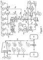
- Fig. 1 shows dynamic compressor 101 pumping gas from source 102 to end user 106.
- Gas enters the compressor through inlet line 103, into which is installed orifice plate 104, and leaves via discharge line 105. Excess flow is recycled to the source 102 via antisurge valve 107.
- Fig. 1 also shows the antisurge control system and its connections to the compression process.
- This control system includes the rotational speed transmitter 108, guide vane position transmitter 109, inlet pressure transmitter 110, the discharge pressure transmitter 111, the inlet temperature transmitter 112, the discharge temperature transmitter 113, the flow rate transmitter 114 (which measures the differential pressure across the flow measuring device 104) and antisurge valve position transducer 115.
- the control system also includes computing and control modules 116 through 135, as described in the following paragraphs.
- Computing module 116 calculates the temperature ratio (R ⁇ )of dynamic compressor 101 as as the ratio of discharge temperature (T d ) to suction temperature (T s ):
- computing module 117 calculates the compression ratio (R c ) as the ratio of discharge pressure (P d ) to suction pressure (P s ):
- Module 120 calculates the reduced polytropic head h red of dynamic compressor 101 as a function of the compression ratio (R c ) and the polytropic exponent ( ⁇ ), as defined by equation 4; module 121 calculates the reduced volumetric flow in suction squared as a function of the differential pressure ( ⁇ P o ) and the inlet pressure (P s ) only, as defined by equation 5; and module 122 calculates the ratio of these two variables, which is the absolute slope (S abs ) of a line from the origin to the operating point when plotted in the coordinates h red vs
- Module 124 then calculates the relative slope of the line from the origin to the operating point by normalizing the absolute slope (S abs ) with respect to the slope of the surge limit (S sl ):
- b3 added margin of safety
- Modules 128 through 131 implement the controller's closed-loop response.
- Module 128 calculates the adaptive control bias (b2) using either of two algorithms: when the compressor operating point is moving toward the surge limit (v rel greater than zero), b2 will be calculated as the greater of its previous value or a second value proportional to v rel . Thus, b2 will be held constant unless the operating point is accelerating toward the surge limit; when the compressor operating point is moving away from the surge limit (v rel less than zero), b2 will be slowly reduced to zero.
- This deviation signal is then passed to the proportional-plus-integral control module (131), which will start to open the antisurge valve (107) when the distance (d rel ) between the operating point and the surge limit shrinks below the safe margin (b).
- Modules 132 through 134 implement the controller's open-loop response, which is triggered when the distance (d rel ) between the operating point and surge limit is less than a minimum threshold level (d t ).
- Summing module 132 computes the value of d t by adding the output (b3) of the surge counter (module 127) to the operator supplied set point (d1).
- Module 133 then generates a binary output indicating whether or not d rel is less than d t , which is used to select the algorithm by which module 134 calculates the value of the open-loop response: if d rel falls below d t , module 134 immediately increments its output by an amount proportional to v rel .
- summation module 135 computes the required antisurge valve position by adding the open-loop response from module 134 to the closed-loop response from module 131. This signal is then sent to transducer 115, which repositions antisurge valve 107 accordingly.
- Fig. 1 The operation of the control system diagrammed in Fig. 1 may be illustrated by the following example (see Fig. 2).
- the set point for the controller's closed-loop response will correspond to point D, where the slope of line OD divided by the slope of line OG is equal to 1-b1.
- the open-loop set point will be at point E, where the slope of line OE divided by the slope of line OG is equal to 1-d1.
- adaptive control module 128 increases the margin of safety (b) by an amount b2, thus moving the closed-loop set point to C.
- the rate of approaching surge (v rel ) will decrease, allowing the margin of safety to return to its normal level b1 and the set point to return to D.
- the antisurge valve (107) stays closed because the operating point stabilizes at B without ever moving to the left of either the closed-loop or open-loop set point.
- the operating point will move back to the right and the set point will slowly return to its steady-state position D.
- the antisurge valve (107) will stabilize at whatever position is needed to keep the load curve at or to the right of position III, allowing the operating point to stabilize at or to the right of point D, where the distance (d rel ) between the operating point and the surge limit is at least as large as the steady state margin of safety (b1).
- Module 134 will then increase the opening of the antisurge valve by a second increment C2, which will be proportional to the derivative of S rel at that point. Due to the control actions already taken, v rel will presumably be smaller at point F than it was at the point E. Thus, the second increment (C2) should be smaller than the first (C1).
- module 134 will stop adding adaptive increments to the valve opening. Although the accumulated open-loop response then decays slowly to zero, the proportional-plus-integral module (131) will continue to increase the valve opening until the load curve returns to position IV. This restores the operating point to position D, where the distance (d rel ) between the operating point and the surge limit is once again equal to the steady state level b1 of the safety margin (b).
- module 123 automatically recomputes the slope of the line through the surge limit point, thus allowing the distance (d rel ) between the operating point and the surge limit to be calculated relative to the slope of a line through the new surge limit point H. Module 123 will also automatically compensate for changes in the position of any guide vanes. Because any movement of the operating point due to changing gas composition or polytropic efficiency will be reflected in the computed value of S rel , this method will be self-adjusting for all such changes.
- closed-loop and open-loop control tailors both responses to the magnitude of each individual disturbance by employing control responses which are dependent on the derivative of the controlled variable in a way that does not produce unneeded valve movements and satisfies the conditions of stability without requiring larger margins of safety.
Applications Claiming Priority (3)
| Application Number | Priority Date | Filing Date | Title |
|---|---|---|---|
| US07/263,172 US4949276A (en) | 1988-10-26 | 1988-10-26 | Method and apparatus for preventing surge in a dynamic compressor |
| US263172 | 1988-10-26 | ||
| EP89302550A EP0366219B1 (de) | 1988-10-26 | 1989-03-15 | Modus und Gerät zur Vermeidung des Pumpens in einem dynamischen Verdichter |
Related Parent Applications (1)
| Application Number | Title | Priority Date | Filing Date |
|---|---|---|---|
| EP89302550.2 Division | 1989-03-15 |
Publications (3)
| Publication Number | Publication Date |
|---|---|
| EP0500196A2 true EP0500196A2 (de) | 1992-08-26 |
| EP0500196A3 EP0500196A3 (en) | 1992-10-21 |
| EP0500196B1 EP0500196B1 (de) | 1994-06-29 |
Family
ID=23000691
Family Applications (3)
| Application Number | Title | Priority Date | Filing Date |
|---|---|---|---|
| EP92201362A Expired - Lifetime EP0500195B1 (de) | 1988-10-26 | 1989-03-15 | Modus und Gerät zur Vermeidung des Pumpens in einem dynamischen Verdichter |
| EP92201363A Expired - Lifetime EP0500196B1 (de) | 1988-10-26 | 1989-03-15 | Modus und Gerät zur Vermeidung des Pumpens in einem dynamischen Verdichter |
| EP89302550A Expired - Lifetime EP0366219B1 (de) | 1988-10-26 | 1989-03-15 | Modus und Gerät zur Vermeidung des Pumpens in einem dynamischen Verdichter |
Family Applications Before (1)
| Application Number | Title | Priority Date | Filing Date |
|---|---|---|---|
| EP92201362A Expired - Lifetime EP0500195B1 (de) | 1988-10-26 | 1989-03-15 | Modus und Gerät zur Vermeidung des Pumpens in einem dynamischen Verdichter |
Family Applications After (1)
| Application Number | Title | Priority Date | Filing Date |
|---|---|---|---|
| EP89302550A Expired - Lifetime EP0366219B1 (de) | 1988-10-26 | 1989-03-15 | Modus und Gerät zur Vermeidung des Pumpens in einem dynamischen Verdichter |
Country Status (7)
| Country | Link |
|---|---|
| US (1) | US4949276A (de) |
| EP (3) | EP0500195B1 (de) |
| CA (1) | CA1291737C (de) |
| DE (3) | DE68916554T2 (de) |
| ES (3) | ES2056687T3 (de) |
| NO (1) | NO174358C (de) |
| ZA (1) | ZA897281B (de) |
Cited By (2)
| Publication number | Priority date | Publication date | Assignee | Title |
|---|---|---|---|---|
| EP0676545A2 (de) * | 1994-04-07 | 1995-10-11 | Compressor Controls Corporation | Verfahren und Gerät zur Regulierung des Pumpens |
| EP2423515A1 (de) * | 2010-08-25 | 2012-02-29 | Siemens Aktiengesellschaft | Industrielles Verdichtersystem |
Families Citing this family (98)
| Publication number | Priority date | Publication date | Assignee | Title |
|---|---|---|---|---|
| US5195875A (en) * | 1991-12-05 | 1993-03-23 | Dresser-Rand Company | Antisurge control system for compressors |
| US5306116A (en) * | 1992-04-10 | 1994-04-26 | Ingersoll-Rand Company | Surge control and recovery for a centrifugal compressor |
| US5347467A (en) * | 1992-06-22 | 1994-09-13 | Compressor Controls Corporation | Load sharing method and apparatus for controlling a main gas parameter of a compressor station with multiple dynamic compressors |
| US5463559A (en) * | 1993-07-19 | 1995-10-31 | Ingersoll-Rand Company | Diagnostic apparatus for an electronic controller |
| US5355691A (en) * | 1993-08-16 | 1994-10-18 | American Standard Inc. | Control method and apparatus for a centrifugal chiller using a variable speed impeller motor drive |
| US5535967A (en) * | 1993-12-20 | 1996-07-16 | Alliedsignal Inc. | Floating speed electrically driven suction system |
| FI104205B1 (fi) * | 1994-11-24 | 1999-11-30 | Sarlin Hydor Oy | Menetelmä ja laitteisto virtaavan väliaineen kompressointijärjestelmän ohjaamiseksi |
| US5537830A (en) * | 1994-11-28 | 1996-07-23 | American Standard Inc. | Control method and appartus for a centrifugal chiller using a variable speed impeller motor drive |
| US5743715A (en) * | 1995-10-20 | 1998-04-28 | Compressor Controls Corporation | Method and apparatus for load balancing among multiple compressors |
| US5599161A (en) * | 1995-11-03 | 1997-02-04 | Compressor Controls Corporation | Method and apparatus for antisurge control of multistage compressors with sidestreams |
| CN1136485C (zh) * | 1996-01-02 | 2004-01-28 | 伍德沃德调控器公司 | 动态压缩机的防冲击控制系统 |
| US5709526A (en) * | 1996-01-02 | 1998-01-20 | Woodward Governor Company | Surge recurrence prevention control system for dynamic compressors |
| US5971712A (en) * | 1996-05-22 | 1999-10-26 | Ingersoll-Rand Company | Method for detecting the occurrence of surge in a centrifugal compressor |
| US5908462A (en) * | 1996-12-06 | 1999-06-01 | Compressor Controls Corporation | Method and apparatus for antisurge control of turbocompressors having surge limit lines with small slopes |
| US5892145A (en) * | 1996-12-18 | 1999-04-06 | Alliedsignal Inc. | Method for canceling the dynamic response of a mass flow sensor using a conditioned reference |
| US6231306B1 (en) | 1998-11-23 | 2001-05-15 | United Technologies Corporation | Control system for preventing compressor stall |
| US6202431B1 (en) * | 1999-01-15 | 2001-03-20 | York International Corporation | Adaptive hot gas bypass control for centrifugal chillers |
| US6332336B1 (en) * | 1999-02-26 | 2001-12-25 | Compressor Controls Corporation | Method and apparatus for maximizing the productivity of a natural gas liquids production plant |
| US6226974B1 (en) * | 1999-06-25 | 2001-05-08 | General Electric Co. | Method of operation of industrial gas turbine for optimal performance |
| DE10012380A1 (de) * | 2000-03-14 | 2001-09-20 | Man Turbomasch Ag Ghh Borsig | Verfahren zum Schutz eines Turbokompressors vor Betrieb im instabilen Arbeitsbereich |
| US6321543B1 (en) * | 2000-03-15 | 2001-11-27 | Carrier Corporation | Method for protecting compressors used in chillers and/or heat pumps |
| NO313926B1 (no) * | 2000-11-08 | 2002-12-23 | Abb Research Ltd | Kompressorstyring |
| DE10304063A1 (de) * | 2003-01-31 | 2004-08-12 | Man Turbomaschinen Ag | Verfahren zum sicheren Betreiben von Turbokompressoren mit einer Pumpgrenzregelung und einem Pumpgrenzregelventil |
| DE10352252B4 (de) * | 2003-11-08 | 2013-09-19 | Alstom Technology Ltd. | Kompressor für eine Turbogruppe |
| US7096669B2 (en) * | 2004-01-13 | 2006-08-29 | Compressor Controls Corp. | Method and apparatus for the prevention of critical process variable excursions in one or more turbomachines |
| US7421853B2 (en) | 2004-01-23 | 2008-09-09 | York International Corporation | Enhanced manual start/stop sequencing controls for a stream turbine powered chiller unit |
| US7328587B2 (en) | 2004-01-23 | 2008-02-12 | York International Corporation | Integrated adaptive capacity control for a steam turbine powered chiller unit |
| US7421854B2 (en) | 2004-01-23 | 2008-09-09 | York International Corporation | Automatic start/stop sequencing controls for a steam turbine powered chiller unit |
| US7094019B1 (en) | 2004-05-17 | 2006-08-22 | Continuous Control Solutions, Inc. | System and method of surge limit control for turbo compressors |
| EP1659294B1 (de) * | 2004-11-17 | 2017-01-11 | Mitsubishi Heavy Industries Compressor Corporation | Verdichtersteuereinheit und Gasturbinenkraftanlage mit dieser Einheit |
| US7089738B1 (en) | 2005-04-09 | 2006-08-15 | Cummins, Inc. | System for controlling turbocharger compressor surge |
| JP2007218586A (ja) * | 2006-02-14 | 2007-08-30 | Yokogawa Electric Corp | マルチバリアブル質量流量伝送器 |
| US7712299B2 (en) * | 2006-09-05 | 2010-05-11 | Conocophillips Company | Anti-bogdown control system for turbine/compressor systems |
| DE102007050797A1 (de) | 2007-10-24 | 2008-07-24 | Daimler Ag | Verfahren zum Betreiben eines Brennstoffzellensystems mit einem in einem Brennstoffzellenkreislauf angeordneten, elektromotorisch angetriebenen Verdichter |
| CN101896773B (zh) * | 2007-12-14 | 2013-06-19 | 开利公司 | 用于具有入口和出口流量控制装置的hvac系统的控制装置 |
| DE102008005354B4 (de) * | 2008-01-21 | 2016-05-25 | Man Diesel & Turbo Se | Verfahren zur Regelung einer Strömungsmaschine |
| DE102008021102A1 (de) * | 2008-04-28 | 2009-10-29 | Siemens Aktiengesellschaft | Wirkungsgradüberwachung eines Verdichters |
| US20090324382A1 (en) * | 2008-05-05 | 2009-12-31 | General Electric Company | Torque-based sensor and control method for varying gas-liquid fractions of fluids for turbomachines |
| EP2304358A2 (de) * | 2008-07-29 | 2011-04-06 | Shell Internationale Research Maatschappij B.V. | Verfahren und vorrichtung zur steuerung eines kompressors und verfahren zur kühlung eines kohlenwasserstoffstroms |
| DE102008058799B4 (de) * | 2008-11-24 | 2012-04-26 | Siemens Aktiengesellschaft | Verfahren zum Betrieb eines mehrstufigen Verdichters |
| US8311684B2 (en) * | 2008-12-17 | 2012-11-13 | Pratt & Whitney Canada Corp. | Output flow control in load compressor |
| US9328949B2 (en) | 2009-03-30 | 2016-05-03 | Tmeic Corporation | Compressor surge control system and method |
| IT1396001B1 (it) * | 2009-04-28 | 2012-11-09 | Nuovo Pignone Spa | Sistema di recupero dell'energia in un impianto per la compressione di gas |
| US8342794B2 (en) * | 2009-05-19 | 2013-01-01 | General Electric Company | Stall and surge detection system and method |
| WO2011020941A1 (es) * | 2009-08-21 | 2011-02-24 | Universidad Politécnica de Madrid | Método y dispositivo para la predicción de la inestabilidad de un compresor axial |
| JP4932886B2 (ja) | 2009-09-30 | 2012-05-16 | 三菱重工コンプレッサ株式会社 | ガス処理装置 |
| US8726678B2 (en) * | 2009-10-20 | 2014-05-20 | Johnson Controls Technology Company | Controllers and methods for providing computerized generation and use of a three dimensional surge map for control of chillers |
| EP2354559A1 (de) | 2010-01-27 | 2011-08-10 | Siemens Aktiengesellschaft | Verdichtersteuerungsverfahren und System |
| US20120100013A9 (en) * | 2010-05-11 | 2012-04-26 | Krishnan Narayanan | Method of surge protection for a dynamic compressor using a surge parameter |
| US10900492B2 (en) | 2010-05-11 | 2021-01-26 | Energy Control Technologies, Inc. | Method of anti-surge protection for a dynamic compressor using a surge parameter |
| NO333438B1 (no) | 2010-07-14 | 2013-06-03 | Statoil Asa | Fremgangsmate og apparat for sammensetningsbasert kompressorkontroll og ytelsesovervaking. |
| RU2453734C1 (ru) * | 2010-10-12 | 2012-06-20 | Закрытое акционерное общество "Научно-исследовательский и конструкторский институт центробежных и роторных компрессоров им. В.Б. Шнеппа" | Способ защиты центробежного компрессора от нестационарной динамической нагрузки |
| IT1402481B1 (it) * | 2010-10-27 | 2013-09-13 | Nuovo Pignone Spa | Metodo e dispositivo che effettua una compensazione del tempo morto di anti-pompaggio basata su modello |
| US9133850B2 (en) | 2011-01-13 | 2015-09-15 | Energy Control Technologies, Inc. | Method for preventing surge in a dynamic compressor using adaptive preventer control system and adaptive safety margin |
| JP5634907B2 (ja) | 2011-02-10 | 2014-12-03 | 株式会社日立製作所 | 圧縮機の制御装置及び制御方法 |
| RU2458257C1 (ru) * | 2011-04-14 | 2012-08-10 | Закрытое акционерное общество "Научно-исследовательский и конструкторский институт центробежных и роторных компрессоров им. В.Б. Шнеппа" | Способ защиты турбокомпрессора от помпажа |
| US10436208B2 (en) * | 2011-06-27 | 2019-10-08 | Energy Control Technologies, Inc. | Surge estimator |
| ITBA20110037A1 (it) * | 2011-07-07 | 2013-01-08 | Ind Plant Consultant Srl | Metodo per la protezione dei compressori centrifughi dal fenomeno del pompaggio |
| ITCO20110069A1 (it) * | 2011-12-20 | 2013-06-21 | Nuovo Pignone Spa | Disposizione di prova per uno stadio di un compressore centrifugo |
| US9074606B1 (en) | 2012-03-02 | 2015-07-07 | Rmoore Controls L.L.C. | Compressor surge control |
| US9097447B2 (en) | 2012-07-25 | 2015-08-04 | Johnson Controls Technology Company | Methods and controllers for providing a surge map for the monitoring and control of chillers |
| ITCO20120056A1 (it) * | 2012-11-07 | 2014-05-08 | Nuovo Pignone Srl | Metodo per operare un compressore in caso di malfunzionamento di uno o piu' segnali di misura |
| JP5738262B2 (ja) * | 2012-12-04 | 2015-06-17 | 三菱重工コンプレッサ株式会社 | 圧縮機制御装置、圧縮機システムおよび圧縮機制御方法 |
| US10018157B2 (en) | 2013-03-14 | 2018-07-10 | Ford Global Technologies, Llc | Methods and systems for boost control |
| ITFI20130063A1 (it) | 2013-03-26 | 2014-09-27 | Nuovo Pignone Srl | "methods and systems for antisurge control of turbo compressors with side stream" |
| US9261051B2 (en) | 2013-08-13 | 2016-02-16 | Ford Global Technologies, Llc | Methods and systems for boost control |
| US9682685B2 (en) | 2013-08-13 | 2017-06-20 | Ford Global Technologies, Llc | Methods and systems for condensation control |
| US9303557B2 (en) | 2013-08-13 | 2016-04-05 | Ford Global Technologies, Llc | Methods and systems for EGR control |
| US9109505B2 (en) | 2013-08-13 | 2015-08-18 | Ford Global Technologies, Llc | Methods and systems for condensation control |
| US9091202B2 (en) | 2013-08-13 | 2015-07-28 | Ford Global Technologies, Llc | Methods and systems for boost control |
| US9174637B2 (en) | 2013-08-13 | 2015-11-03 | Ford Global Technologies, Llc | Methods and systems for torque control |
| US9309837B2 (en) | 2013-08-13 | 2016-04-12 | Ford Global Technologies, Llc | Methods and systems for EGR control |
| US9279374B2 (en) | 2013-08-13 | 2016-03-08 | Ford Global Technologies, Llc | Methods and systems for surge control |
| US9080506B2 (en) | 2013-08-13 | 2015-07-14 | Ford Global Technologies, Llc | Methods and systems for boost control |
| US9309836B2 (en) | 2013-08-13 | 2016-04-12 | Ford Global Technologies, Llc | Methods and systems for boost control |
| US9151219B2 (en) | 2013-08-13 | 2015-10-06 | Ford Global Technologies, Llc | Methods and systems for surge control |
| US9759135B2 (en) | 2014-04-04 | 2017-09-12 | Ford Global Technologies, Llc | Method and system for engine control |
| JP6501380B2 (ja) * | 2014-07-01 | 2019-04-17 | 三菱重工コンプレッサ株式会社 | 多段圧縮機システム、制御装置、異常判定方法及びプログラム |
| US9551276B2 (en) * | 2014-08-14 | 2017-01-24 | Ford Global Technologies, Llc | Methods and systems for surge control |
| US11686517B2 (en) | 2014-11-14 | 2023-06-27 | Carrier Corporation | On board chiller capacity calculation |
| RU2613758C2 (ru) * | 2015-08-14 | 2017-03-21 | Открытое акционерное общество "Уфимское моторостроительное производственное объединение" ОАО "УМПО" | Способ защиты двухконтурного турбореактивного двигателя от помпажа при эксплуатации |
| US10254719B2 (en) | 2015-09-18 | 2019-04-09 | Statistics & Control, Inc. | Method and apparatus for surge prevention control of multistage compressor having one surge valve and at least one flow measuring device |
| US11143056B2 (en) | 2016-08-17 | 2021-10-12 | General Electric Company | System and method for gas turbine compressor cleaning |
| RU171843U1 (ru) * | 2016-09-22 | 2017-06-19 | Открытое акционерное общество "Севернефтегазпром" | Компоновка вала центробежного компрессора |
| RU2638896C1 (ru) * | 2017-03-14 | 2017-12-18 | федеральное государственное бюджетное образовательное учреждение высшего образования "Уфимский государственный авиационный технический университет" | Способ диагностики помпажа компрессора газотурбинного двигателя и устройство для его реализации |
| EP3396169B1 (de) * | 2017-04-27 | 2022-01-12 | Cryostar SAS | Verfahren zur steuerung eines mehrstufigen kompressors |
| US10590836B2 (en) * | 2018-01-24 | 2020-03-17 | Ford Global Technologies, Llc | System and method for controlling surge margin in a boosted engine system |
| JP6952621B2 (ja) * | 2018-02-26 | 2021-10-20 | 三菱重工コンプレッサ株式会社 | 性能評価方法、性能評価装置、及び性能評価システム |
| RU2713782C1 (ru) * | 2019-01-09 | 2020-02-07 | Акционерное общество "Инжиниринговая компания "АЭМ-технологии" (АО "АЭМ-технологии") | Способ защиты центробежного нагнетателя от помпажа |
| EP3921548A1 (de) * | 2019-02-06 | 2021-12-15 | Compressor Controls Corporation | Systeme und verfahren zur anpassung eines verdichtersteuergeräts auf basis der feldbedingungen |
| GB201912322D0 (en) | 2019-08-28 | 2019-10-09 | Rolls Royce Plc | Gas turbine engine flow control |
| CN111271303B (zh) * | 2020-01-22 | 2021-01-01 | 西安陕鼓通风设备有限公司 | 一种油站电控系统、通风机组控制系统及控制方法 |
| US11448088B2 (en) | 2020-02-14 | 2022-09-20 | Honeywell International Inc. | Temperature inversion detection and mitigation strategies to avoid compressor surge |
| US11578727B2 (en) * | 2020-09-17 | 2023-02-14 | Compressor Controls Llc | Methods and system for control of compressors with both variable speed and guide vanes position |
| CN112302987B (zh) * | 2020-10-30 | 2022-07-15 | 中国航发沈阳发动机研究所 | 应对温度畸变的航空发动机压缩部件可调导叶调节方法 |
| US11434917B1 (en) * | 2021-07-13 | 2022-09-06 | Roman Bershader | Methodology and algorithms for protecting centrifugal and axial compressors from surge and choke |
| CN114562476B (zh) * | 2021-12-24 | 2024-03-29 | 浙江中控技术股份有限公司 | 一种压缩机机组冷热回流的控制方法 |
| CN114876846B (zh) * | 2022-06-01 | 2024-03-26 | 西安陕鼓动力股份有限公司 | 一种离心压缩机组全自动恒压控制系统及控制方法 |
Citations (1)
| Publication number | Priority date | Publication date | Assignee | Title |
|---|---|---|---|---|
| US4142838A (en) | 1977-12-01 | 1979-03-06 | Compressor Controls Corporation | Method and apparatus for preventing surge in a dynamic compressor |
Family Cites Families (15)
| Publication number | Priority date | Publication date | Assignee | Title |
|---|---|---|---|---|
| DE1428066A1 (de) * | 1963-08-30 | 1968-11-28 | Continental Elektro Ind Ag | Grenzmengenregelung an Turboverdichtern |
| US3979655A (en) * | 1975-03-31 | 1976-09-07 | Compressor Controls Corporation | Control system for controlling a dynamic compressor |
| US4046490A (en) * | 1975-12-01 | 1977-09-06 | Compressor Controls Corporation | Method and apparatus for antisurge protection of a dynamic compressor |
| US4139328A (en) * | 1977-05-25 | 1979-02-13 | Gutehoffnungshitte Sterkrade Ag | Method of operating large turbo compressors |
| US4164033A (en) * | 1977-09-14 | 1979-08-07 | Sundstrand Corporation | Compressor surge control with airflow measurement |
| US4486142A (en) * | 1977-12-01 | 1984-12-04 | Naum Staroselsky | Method of automatic limitation for a controlled variable in a multivariable system |
| US4355948A (en) * | 1979-09-12 | 1982-10-26 | Borg-Warner Corporation | Adjustable surge and capacity control system |
| US4627788A (en) * | 1984-08-20 | 1986-12-09 | The Babcock & Wilcox Company | Adaptive gain compressor surge control system |
| US4594050A (en) * | 1984-05-14 | 1986-06-10 | Dresser Industries, Inc. | Apparatus and method for detecting surge in a turbo compressor |
| US4697980A (en) * | 1984-08-20 | 1987-10-06 | The Babcock & Wilcox Company | Adaptive gain compressor surge control system |
| DE3540088A1 (de) * | 1985-11-12 | 1987-05-14 | Gutehoffnungshuette Man | Verfahren zur erfassung von pumpstoessen an turbokompressoren |
| DE3544822A1 (de) * | 1985-12-18 | 1987-06-19 | Gutehoffnungshuette Man | Verfahren zur pumpgrenzregelung von turbokomporessoren |
| DE3544821A1 (de) * | 1985-12-18 | 1987-06-19 | Gutehoffnungshuette Man | Verfahren zum regeln von turbokompressoren zur vermeidung des pumpens |
| US4807150A (en) * | 1986-10-02 | 1989-02-21 | Phillips Petroleum Company | Constraint control for a compressor system |
| US4781524A (en) * | 1987-02-12 | 1988-11-01 | Man Gutehoffnungshuette Gmbh | Method and apparatus for detecting pressure surges in a turbo-compressor |
-
1988
- 1988-10-26 US US07/263,172 patent/US4949276A/en not_active Expired - Lifetime
-
1989
- 1989-03-15 ES ES92201363T patent/ES2056687T3/es not_active Expired - Lifetime
- 1989-03-15 DE DE68916554T patent/DE68916554T2/de not_active Expired - Fee Related
- 1989-03-15 ES ES92201362T patent/ES2056686T3/es not_active Expired - Lifetime
- 1989-03-15 EP EP92201362A patent/EP0500195B1/de not_active Expired - Lifetime
- 1989-03-15 EP EP92201363A patent/EP0500196B1/de not_active Expired - Lifetime
- 1989-03-15 ES ES89302550T patent/ES2045411T3/es not_active Expired - Lifetime
- 1989-03-15 EP EP89302550A patent/EP0366219B1/de not_active Expired - Lifetime
- 1989-03-15 DE DE68910467T patent/DE68910467T2/de not_active Expired - Lifetime
- 1989-03-15 DE DE68916555T patent/DE68916555T2/de not_active Expired - Lifetime
- 1989-03-21 NO NO891239A patent/NO174358C/no unknown
- 1989-04-12 CA CA000596551A patent/CA1291737C/en not_active Expired - Lifetime
- 1989-09-25 ZA ZA897281A patent/ZA897281B/xx unknown
Patent Citations (1)
| Publication number | Priority date | Publication date | Assignee | Title |
|---|---|---|---|---|
| US4142838A (en) | 1977-12-01 | 1979-03-06 | Compressor Controls Corporation | Method and apparatus for preventing surge in a dynamic compressor |
Cited By (4)
| Publication number | Priority date | Publication date | Assignee | Title |
|---|---|---|---|---|
| EP0676545A2 (de) * | 1994-04-07 | 1995-10-11 | Compressor Controls Corporation | Verfahren und Gerät zur Regulierung des Pumpens |
| EP0676545A3 (de) * | 1994-04-07 | 1997-07-02 | Compressor Controls Corp | Verfahren und Gerät zur Regulierung des Pumpens. |
| EP2423515A1 (de) * | 2010-08-25 | 2012-02-29 | Siemens Aktiengesellschaft | Industrielles Verdichtersystem |
| WO2012025305A1 (en) * | 2010-08-25 | 2012-03-01 | Siemens Aktiengesellschaft | Industrial compressor system |
Also Published As
| Publication number | Publication date |
|---|---|
| EP0500196A3 (en) | 1992-10-21 |
| EP0366219A3 (en) | 1990-12-12 |
| NO891239D0 (no) | 1989-03-21 |
| DE68916555T2 (de) | 1994-10-20 |
| DE68910467T2 (de) | 1994-06-01 |
| EP0500195B1 (de) | 1994-06-29 |
| EP0500196B1 (de) | 1994-06-29 |
| NO891239L (no) | 1990-04-27 |
| EP0366219B1 (de) | 1993-11-03 |
| DE68916554D1 (de) | 1994-08-04 |
| US4949276A (en) | 1990-08-14 |
| ES2056686T3 (es) | 1994-10-01 |
| DE68916555D1 (de) | 1994-08-04 |
| DE68910467D1 (de) | 1993-12-09 |
| DE68916554T2 (de) | 1994-10-20 |
| ZA897281B (en) | 1990-07-25 |
| EP0500195A2 (de) | 1992-08-26 |
| NO174358B (no) | 1994-01-10 |
| NO174358C (no) | 1994-04-20 |
| ES2056687T3 (es) | 1994-10-01 |
| EP0500195A3 (en) | 1992-10-14 |
| EP0366219A2 (de) | 1990-05-02 |
| CA1291737C (en) | 1991-11-05 |
| ES2045411T3 (es) | 1994-01-16 |
Similar Documents
| Publication | Publication Date | Title |
|---|---|---|
| EP0500196B1 (de) | Modus und Gerät zur Vermeidung des Pumpens in einem dynamischen Verdichter | |
| US6551068B2 (en) | Process for protecting a turbocompressor from operating in the unstable working range | |
| CA2231444C (en) | Surge recurrence prevention control system for dynamic compressors | |
| US4627788A (en) | Adaptive gain compressor surge control system | |
| RU2168071C2 (ru) | Способ измерения расстояния от рабочей точки турбокомпрессора до границы помпажа турбокомпрессора (варианты) и устройство для определения положения рабочей точки турбокомпрессора относительно границы помпажа турбокомпрессора (варианты) | |
| US5385012A (en) | Bleed valve control | |
| US4640665A (en) | Method for controlling a multicompressor station | |
| US4164033A (en) | Compressor surge control with airflow measurement | |
| US3276674A (en) | Method for preventing surging of compressors | |
| US4697980A (en) | Adaptive gain compressor surge control system | |
| US3994623A (en) | Method and apparatus for controlling a dynamic compressor | |
| US4102604A (en) | Method and apparatus for noninteracting control of a dynamic compressor having rotating vanes | |
| CN111536069B (zh) | 单级高速离心压缩机的防喘振控制方法 | |
| US4494006A (en) | Method and apparatus for controlling a multicompressor station | |
| US4968215A (en) | Device for control of a turbocompressor | |
| US4938658A (en) | Method of reliably operating turbocompressors | |
| US3979655A (en) | Control system for controlling a dynamic compressor | |
| US4946343A (en) | Method of regulation that prevents surge in a turbocompressor | |
| US4861233A (en) | Compressor surge control system | |
| EP0140499B1 (de) | Verdichter mit Kontrolle des Pumpens | |
| US4900232A (en) | Compressor surge control method | |
| CN114413548B (zh) | 一种变频离心式冷水机组及其控制方法和存储介质 | |
| US5699267A (en) | Hot gas expander power recovery and control | |
| SU1590676A1 (ru) | Способ защиты компрессора от помпажа и устройство дл его осуществлени | |
| RU126385U1 (ru) | Система противопомпажного регулирования и защиты турбокомпрессора |
Legal Events
| Date | Code | Title | Description |
|---|---|---|---|
| PUAI | Public reference made under article 153(3) epc to a published international application that has entered the european phase |
Free format text: ORIGINAL CODE: 0009012 |
|
| 17P | Request for examination filed |
Effective date: 19920525 |
|
| AC | Divisional application: reference to earlier application |
Ref document number: 366219 Country of ref document: EP |
|
| AK | Designated contracting states |
Kind code of ref document: A2 Designated state(s): BE CH DE ES FR GB IT LI NL |
|
| PUAL | Search report despatched |
Free format text: ORIGINAL CODE: 0009013 |
|
| AK | Designated contracting states |
Kind code of ref document: A3 Designated state(s): BE CH DE ES FR GB IT LI NL |
|
| RIN1 | Information on inventor provided before grant (corrected) |
Inventor name: MIRSKY, SAUL Inventor name: STAROSELSKY, NAUM Inventor name: REINKE, PAUL A. |
|
| RIN1 | Information on inventor provided before grant (corrected) |
Inventor name: REINKE, PAUL A. Inventor name: STAROSELSKY, NAUM Inventor name: MIRSKY, SAUL |
|
| 17Q | First examination report despatched |
Effective date: 19930929 |
|
| GRAA | (expected) grant |
Free format text: ORIGINAL CODE: 0009210 |
|
| ITF | It: translation for a ep patent filed |
Owner name: BARZANO' E ZANARDO MILANO S.P.A. |
|
| AC | Divisional application: reference to earlier application |
Ref document number: 366219 Country of ref document: EP |
|
| AK | Designated contracting states |
Kind code of ref document: B1 Designated state(s): BE CH DE ES FR GB IT LI NL |
|
| REF | Corresponds to: |
Ref document number: 68916555 Country of ref document: DE Date of ref document: 19940804 |
|
| ET | Fr: translation filed | ||
| REG | Reference to a national code |
Ref country code: ES Ref legal event code: FG2A Ref document number: 2056687 Country of ref document: ES Kind code of ref document: T3 |
|
| PLBE | No opposition filed within time limit |
Free format text: ORIGINAL CODE: 0009261 |
|
| STAA | Information on the status of an ep patent application or granted ep patent |
Free format text: STATUS: NO OPPOSITION FILED WITHIN TIME LIMIT |
|
| 26N | No opposition filed | ||
| PGFP | Annual fee paid to national office [announced via postgrant information from national office to epo] |
Ref country code: BE Payment date: 20000228 Year of fee payment: 12 |
|
| PGFP | Annual fee paid to national office [announced via postgrant information from national office to epo] |
Ref country code: ES Payment date: 20000302 Year of fee payment: 12 |
|
| PGFP | Annual fee paid to national office [announced via postgrant information from national office to epo] |
Ref country code: CH Payment date: 20000328 Year of fee payment: 12 |
|
| PG25 | Lapsed in a contracting state [announced via postgrant information from national office to epo] |
Ref country code: ES Free format text: LAPSE BECAUSE OF NON-PAYMENT OF DUE FEES Effective date: 20010316 |
|
| PG25 | Lapsed in a contracting state [announced via postgrant information from national office to epo] |
Ref country code: BE Free format text: LAPSE BECAUSE OF NON-PAYMENT OF DUE FEES Effective date: 20010331 Ref country code: CH Free format text: LAPSE BECAUSE OF NON-PAYMENT OF DUE FEES Effective date: 20010331 Ref country code: LI Free format text: LAPSE BECAUSE OF NON-PAYMENT OF DUE FEES Effective date: 20010331 |
|
| BERE | Be: lapsed |
Owner name: COMPRESSOR CONTROLS CORP. Effective date: 20010331 |
|
| REG | Reference to a national code |
Ref country code: CH Ref legal event code: PL |
|
| REG | Reference to a national code |
Ref country code: GB Ref legal event code: IF02 |
|
| PGFP | Annual fee paid to national office [announced via postgrant information from national office to epo] |
Ref country code: FR Payment date: 20030326 Year of fee payment: 15 |
|
| REG | Reference to a national code |
Ref country code: ES Ref legal event code: FD2A Effective date: 20030303 |
|
| PG25 | Lapsed in a contracting state [announced via postgrant information from national office to epo] |
Ref country code: FR Free format text: LAPSE BECAUSE OF NON-PAYMENT OF DUE FEES Effective date: 20041130 |
|
| REG | Reference to a national code |
Ref country code: FR Ref legal event code: ST |
|
| PG25 | Lapsed in a contracting state [announced via postgrant information from national office to epo] |
Ref country code: IT Free format text: LAPSE BECAUSE OF NON-PAYMENT OF DUE FEES Effective date: 20050315 |
|
| PGFP | Annual fee paid to national office [announced via postgrant information from national office to epo] |
Ref country code: NL Payment date: 20080328 Year of fee payment: 20 Ref country code: GB Payment date: 20080312 Year of fee payment: 20 |
|
| PGFP | Annual fee paid to national office [announced via postgrant information from national office to epo] |
Ref country code: DE Payment date: 20080319 Year of fee payment: 20 |
|
| REG | Reference to a national code |
Ref country code: GB Ref legal event code: PE20 Expiry date: 20090314 |
|
| NLV7 | Nl: ceased due to reaching the maximum lifetime of a patent |
Effective date: 20090315 |
|
| PG25 | Lapsed in a contracting state [announced via postgrant information from national office to epo] |
Ref country code: NL Free format text: LAPSE BECAUSE OF EXPIRATION OF PROTECTION Effective date: 20090315 |
|
| PG25 | Lapsed in a contracting state [announced via postgrant information from national office to epo] |
Ref country code: GB Free format text: LAPSE BECAUSE OF EXPIRATION OF PROTECTION Effective date: 20090314 |