EP0498575A2 - Interferometer mit 2-Farben geregelten Laserdioden - Google Patents
Interferometer mit 2-Farben geregelten Laserdioden Download PDFInfo
- Publication number
- EP0498575A2 EP0498575A2 EP92300839A EP92300839A EP0498575A2 EP 0498575 A2 EP0498575 A2 EP 0498575A2 EP 92300839 A EP92300839 A EP 92300839A EP 92300839 A EP92300839 A EP 92300839A EP 0498575 A2 EP0498575 A2 EP 0498575A2
- Authority
- EP
- European Patent Office
- Prior art keywords
- wavelength
- laser diode
- output
- optical
- source
- Prior art date
- Legal status (The legal status is an assumption and is not a legal conclusion. Google has not performed a legal analysis and makes no representation as to the accuracy of the status listed.)
- Granted
Links
- 230000003287 optical effect Effects 0.000 claims abstract description 80
- 238000005259 measurement Methods 0.000 claims abstract description 59
- BJQHLKABXJIVAM-UHFFFAOYSA-N bis(2-ethylhexyl) phthalate Chemical compound CCCCC(CC)COC(=O)C1=CC=CC=C1C(=O)OCC(CC)CCCC BJQHLKABXJIVAM-UHFFFAOYSA-N 0.000 claims abstract description 30
- 238000006073 displacement reaction Methods 0.000 claims description 12
- 238000012937 correction Methods 0.000 claims description 9
- 230000002596 correlated effect Effects 0.000 claims description 2
- 230000005855 radiation Effects 0.000 claims 10
- 238000005070 sampling Methods 0.000 claims 2
- 230000006641 stabilisation Effects 0.000 abstract description 19
- 238000011105 stabilization Methods 0.000 abstract description 19
- 238000005305 interferometry Methods 0.000 abstract description 15
- 230000007774 longterm Effects 0.000 abstract description 8
- 238000000926 separation method Methods 0.000 description 14
- 238000000034 method Methods 0.000 description 13
- 230000008901 benefit Effects 0.000 description 5
- 238000004422 calculation algorithm Methods 0.000 description 5
- 230000000875 corresponding effect Effects 0.000 description 5
- 230000008859 change Effects 0.000 description 4
- 238000004458 analytical method Methods 0.000 description 3
- 238000013459 approach Methods 0.000 description 3
- 230000000694 effects Effects 0.000 description 3
- 230000007613 environmental effect Effects 0.000 description 3
- 238000012986 modification Methods 0.000 description 3
- 230000004048 modification Effects 0.000 description 3
- 230000010355 oscillation Effects 0.000 description 3
- 230000000087 stabilizing effect Effects 0.000 description 3
- 230000009897 systematic effect Effects 0.000 description 3
- 230000005540 biological transmission Effects 0.000 description 2
- 230000001276 controlling effect Effects 0.000 description 2
- 238000012360 testing method Methods 0.000 description 2
- 229910001374 Invar Inorganic materials 0.000 description 1
- 230000002411 adverse Effects 0.000 description 1
- 230000003321 amplification Effects 0.000 description 1
- 230000001427 coherent effect Effects 0.000 description 1
- 230000002301 combined effect Effects 0.000 description 1
- 230000008602 contraction Effects 0.000 description 1
- 230000007812 deficiency Effects 0.000 description 1
- 230000001419 dependent effect Effects 0.000 description 1
- 238000013461 design Methods 0.000 description 1
- 238000010586 diagram Methods 0.000 description 1
- 230000009977 dual effect Effects 0.000 description 1
- 238000002474 experimental method Methods 0.000 description 1
- 238000001093 holography Methods 0.000 description 1
- 238000003384 imaging method Methods 0.000 description 1
- 238000000691 measurement method Methods 0.000 description 1
- 238000003199 nucleic acid amplification method Methods 0.000 description 1
- 238000005191 phase separation Methods 0.000 description 1
- 239000010453 quartz Substances 0.000 description 1
- 230000009467 reduction Effects 0.000 description 1
- 230000006903 response to temperature Effects 0.000 description 1
- VYPSYNLAJGMNEJ-UHFFFAOYSA-N silicon dioxide Inorganic materials O=[Si]=O VYPSYNLAJGMNEJ-UHFFFAOYSA-N 0.000 description 1
- 238000001228 spectrum Methods 0.000 description 1
Images


Classifications
-
- G—PHYSICS
- G01—MEASURING; TESTING
- G01J—MEASUREMENT OF INTENSITY, VELOCITY, SPECTRAL CONTENT, POLARISATION, PHASE OR PULSE CHARACTERISTICS OF INFRARED, VISIBLE OR ULTRAVIOLET LIGHT; COLORIMETRY; RADIATION PYROMETRY
- G01J9/00—Measuring optical phase difference; Determining degree of coherence; Measuring optical wavelength
- G01J9/02—Measuring optical phase difference; Determining degree of coherence; Measuring optical wavelength by interferometric methods
-
- G—PHYSICS
- G01—MEASURING; TESTING
- G01B—MEASURING LENGTH, THICKNESS OR SIMILAR LINEAR DIMENSIONS; MEASURING ANGLES; MEASURING AREAS; MEASURING IRREGULARITIES OF SURFACES OR CONTOURS
- G01B9/00—Measuring instruments characterised by the use of optical techniques
- G01B9/02—Interferometers
- G01B9/02055—Reduction or prevention of errors; Testing; Calibration
- G01B9/02062—Active error reduction, i.e. varying with time
- G01B9/02067—Active error reduction, i.e. varying with time by electronic control systems, i.e. using feedback acting on optics or light
- G01B9/02069—Synchronization of light source or manipulator and detector
-
- G—PHYSICS
- G01—MEASURING; TESTING
- G01B—MEASURING LENGTH, THICKNESS OR SIMILAR LINEAR DIMENSIONS; MEASURING ANGLES; MEASURING AREAS; MEASURING IRREGULARITIES OF SURFACES OR CONTOURS
- G01B9/00—Measuring instruments characterised by the use of optical techniques
- G01B9/02—Interferometers
- G01B9/02001—Interferometers characterised by controlling or generating intrinsic radiation properties
- G01B9/02007—Two or more frequencies or sources used for interferometric measurement
-
- G—PHYSICS
- G01—MEASURING; TESTING
- G01B—MEASURING LENGTH, THICKNESS OR SIMILAR LINEAR DIMENSIONS; MEASURING ANGLES; MEASURING AREAS; MEASURING IRREGULARITIES OF SURFACES OR CONTOURS
- G01B9/00—Measuring instruments characterised by the use of optical techniques
- G01B9/02—Interferometers
- G01B9/02055—Reduction or prevention of errors; Testing; Calibration
- G01B9/02075—Reduction or prevention of errors; Testing; Calibration of particular errors
- G01B9/02078—Caused by ambiguity
-
- H—ELECTRICITY
- H01—ELECTRIC ELEMENTS
- H01S—DEVICES USING THE PROCESS OF LIGHT AMPLIFICATION BY STIMULATED EMISSION OF RADIATION [LASER] TO AMPLIFY OR GENERATE LIGHT; DEVICES USING STIMULATED EMISSION OF ELECTROMAGNETIC RADIATION IN WAVE RANGES OTHER THAN OPTICAL
- H01S5/00—Semiconductor lasers
- H01S5/06—Arrangements for controlling the laser output parameters, e.g. by operating on the active medium
- H01S5/068—Stabilisation of laser output parameters
- H01S5/0683—Stabilisation of laser output parameters by monitoring the optical output parameters
- H01S5/0687—Stabilising the frequency of the laser
-
- G—PHYSICS
- G01—MEASURING; TESTING
- G01B—MEASURING LENGTH, THICKNESS OR SIMILAR LINEAR DIMENSIONS; MEASURING ANGLES; MEASURING AREAS; MEASURING IRREGULARITIES OF SURFACES OR CONTOURS
- G01B2290/00—Aspects of interferometers not specifically covered by any group under G01B9/02
- G01B2290/25—Fabry-Perot in interferometer, e.g. etalon, cavity
-
- G—PHYSICS
- G01—MEASURING; TESTING
- G01B—MEASURING LENGTH, THICKNESS OR SIMILAR LINEAR DIMENSIONS; MEASURING ANGLES; MEASURING AREAS; MEASURING IRREGULARITIES OF SURFACES OR CONTOURS
- G01B2290/00—Aspects of interferometers not specifically covered by any group under G01B9/02
- G01B2290/45—Multiple detectors for detecting interferometer signals
-
- G—PHYSICS
- G01—MEASURING; TESTING
- G01B—MEASURING LENGTH, THICKNESS OR SIMILAR LINEAR DIMENSIONS; MEASURING ANGLES; MEASURING AREAS; MEASURING IRREGULARITIES OF SURFACES OR CONTOURS
- G01B2290/00—Aspects of interferometers not specifically covered by any group under G01B9/02
- G01B2290/60—Reference interferometer, i.e. additional interferometer not interacting with object
-
- H—ELECTRICITY
- H01—ELECTRIC ELEMENTS
- H01S—DEVICES USING THE PROCESS OF LIGHT AMPLIFICATION BY STIMULATED EMISSION OF RADIATION [LASER] TO AMPLIFY OR GENERATE LIGHT; DEVICES USING STIMULATED EMISSION OF ELECTROMAGNETIC RADIATION IN WAVE RANGES OTHER THAN OPTICAL
- H01S5/00—Semiconductor lasers
- H01S5/40—Arrangement of two or more semiconductor lasers, not provided for in groups H01S5/02 - H01S5/30
Definitions
- This invention relates generally to interferometers and, in particular, to a wavelength stabilized two source interferometer.
- Interferometric measurements using phase-modulation or optical heterodyne techniques are presently capable of measurement resolutions of one nanometer. Because of phase ambiguities, these are typically relative measurements of displacement from an initial position with a limit on the allowable displacement between measurements of ⁇ /4, where ⁇ is the source wavelength. For near-infrared sources, such as GaAlAs laser diodes, ⁇ /4 is on the order of 200nm. However, this ambiguity interval is sufficiently small that air turbulence vibration or momentary interruptions of the beam may adversely affect phase tracking techniques for displacement measurement. Furthermore, if the measurement bandwidth is low, phase tracking may not be possible and the dynamic range is reduced to the ⁇ /4 ambiguity interval.
- two wavelengths can be employed to generate a synthetic wavelength ⁇ that is longer than either of the optical wavelengths ⁇ 1 or ⁇ 2.
- interferometric metrology can be performed within the significantly larger range of ⁇ /4, without ambiguity and without sacrificing the accuracy of the single-source instrument.
- optical separation fringe number, fringe order and uncertainty are introduced and defined for use in the subsequent consideration of the two color system of the invention.
- the optical separation is considered to be a one-way difference in optical path length, including the refractive index, for the reference and object beams in the interferometer.
- MAX and ⁇ m
- the advantage presented by this approach is that the synthetic fringe number M varies more slowly with L than either one of the optical fringe numbers m1, m2.
- changes in the integer part of m due to variation in optical separation L that are less than ⁇ /2 may be determined by referring to the measured fractional part of the synthetic fringe number M.
- This can be useful for a number of applications, such as a laser gage operated intermittently, an optical metrology system using a course-grid detector array, a discontinuous surface, or a rough surface.
- the synthetic wavelength determination of changes in the optical fringe order are meaningful only if errors ⁇ L ⁇ in the synthetic wavelength measurement and ⁇ L ⁇ in the optical wavelength measurement are within ⁇ /4 of each other. This condition can be expressed as
- the optical measurement may be taken as the average of the measurements for ⁇ 1 and ⁇ 2:
- Equation (18) was employed to generate the curves shown in Fig. 1.
- Wavelength stability is determined by the requirement that the error in the synthetic wavelength measurement be small enough to permit unambiguous determination of the integer part of the optical fringe order.
- the coefficient of thermal expansion for a typical laser diode is approximately 80ppm/C.
- Such a small thermal tolerance is impractical to achieve based on control of the temperature of the laser diode mount. This is particularly true if the laser diodes are contained in standard packages and are used with commercially available thermoelectric coolers. It is again noted that if the stabilization criterion is not met the synthetic wavelength will be of no use whatsoever in resolving the optical fringe order.
- a known technique for stabilizing a laser diode is to use an external frequency standard or optical spectrum analyzer that senses variations in diode temperature through a measurement of the laser diode emission wavelength. Fine control of the laser diode temperature is achieved by electronic feedback to the diode pump current, thereby altering the equilibrium temperature of the diode with respect to its mount.
- a Fabry-Perot etalon is frequently used for this purpose.
- both laser diodes in a two-color source were to be controlled by two independent Fabry-Perot etalons, then optical path length variations due to mechanical or thermal distortions in the individual etalon cavities are uncorrelated and Eq. (20) still applies, although with a smaller value of ⁇ .
- apparatus and method for controlling and overcoming thermally-induced wavelength drift in a two laser diode interferometric apparatus are provided.
- Upper limits on the wavelength uncertainty for independent laser diodes in a two-color interferometer are derived and are expressed as a function of the optical path difference between object and reference beams, noise-dependent phase demodulation errors and synthetic wavelength.
- the sole function of the synthetic phase is to resolve the phase ambiguities in the optical wavelength data over a displacement range equal to one-half of the synthetic wavelength.
- a synthetic wavelength of 15 ⁇ m requires wavelength stabilities on the order of 0.01ppm for a 250mm one-way optical path difference.
- a wavelength stabilization technique of the invention involves simultaneous control of two laser diodes by electronic feedback from a single, common Fabry-Perot spectrometer.
- This technique has the advantage that variations in the length of the common Fabry-Perot cavity does not contribute to a relative error between optical and synthetic-wavelength measurements.
- the system of the invention is more compact and reliable than those systems of the prior art using independent stabilization, and furthermore permits the extension of current two-color laser-diodes techniques to applications requiring long-term stability over large optical path distances.
- the use of the invention beneficially removes the phase ambiguity in conventional interferometers by employing two laser diodes of different optical frequency to generate a synthetic wavelength.
- Upper limits of the optical wavelength uncertainty are derived and are expressed as a function of optical path difference between object and reference beams, phase measurement errors and the synthetic wavelength.
- the invention provides a relatively simple wavelength stabilization arrangement that involves simultaneous servo control of both laser diodes with a single Fabry-Perot etalon.
- the wavelength stabilization system of the invention is shown to be effective for long term stabilized two-color interferometry over a distance of 250mm with a 15 micron synthetic wavelength and a repeatability of 40nm. For periods of less than 1000 seconds, the repeatability is shown to be eight nanometers.
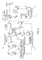
- FIG. 2 there is shown an embodiment of the invention wherein a single external etalon is employed to control the wavelength stabilization of two laser diodes.
- An interferometer system 1 includes a two color source 2, an interferometer 3 and, in accordance with the invention, a dual wavelength control 4.
- Source 2 is comprised of a first laser diode (LD1) 10 and a second laser diode (LD2) 12, each being coupled to an associated power supply 10a and 12a.
- LD1 first laser diode
- LD2 second laser diode
- LD1 and LD2 may be two commercially available laser diodes known in the art as Sharp LTO27MDO and LTO15MDO devices having wavelengths of 785 nm and 828 nm, respectively, for a resulting synthetic wavelength of approximately 15 ⁇ m. These wavelengths are sufficiently well separated to permit the use of common-path optics and interference filters for separation of the wavelengths for the phase measurements and for wavelength stabilization.
- An isolator 14 is provided to prevent optical feedback from entering the laser diodes.
- the outputs of LD1 and LD2 are provided to a spatial filter 16 which creates a spatially coherent colinear beam for each diode output and prevents any misalignment between the beams from LD1 and LD2 from contributing to uncorrelated errors.
- the output of the spatial filter 16 forms the output of the two-color source 2.
- the interferometer 3 there is provided a beamsplitter 18 which provides a reference beam to a reference mirror 20 that is coupled to a PZT actuator 22.
- the dithering of the PZT actuator 22 phase modulates the colinear reference beams.
- An output beam is provided to an object mirror 24 for measuring the displacement of the object.
- the interferometer system 1 operates over a range of zero to 250 mm with a resolution of two nanometers.
- the reflected reference and object beams are provided to interference filters F1 26 and F2 28 and to corresponding photodiode detectors D1 30 and D2 32, respectively.
- a processor 34 is coupled to the outputs of the detectors 30 and 32 for measuring the phase ⁇ in accordance with, by example, a modification of the five-points algorithm described by Schwider et al. "Digital Wave-front Measuring Interferometry: Some Systematic Error Sources", Appl. Opt. 22, 3421 (1983) and by Hariharan et al. “Digital Phase-shifting Interferometry: A Simple Error-compensating Phase Calculation Algorithm", Appl. Opt. 26 (13) 2504-2506 (1987).
- the reference mirror 20 is moved axially to five discrete positions, and the outputs photodiode detectors 30 and 32 are sampled at both wavelengths for each of the five positions.
- An additional modification to this procedure involves an explicit extension of the phase measurement ⁇ over the full 2 ⁇ range.
- a single Fabry Perot etalon 36 that is disposed for receiving a portion of the outputs from both LD1 10 and LD2 12.
- etalon 36 is a 2.5 cm confocal air-spaced structure.
- An output of the etalon 36 is provided to interference filters F1′ 38 and F2′ 40.
- Outputs of the two filters 38 and 40 are provided to respective photodiode detectors D1′ 42 and D2′ 44.
- DC outputs of the detectors 42 and 44 are fed back to the power supplies 10a and 12a of LD1 10 and LD1 12, respectively, for providing pump current fine control of diode temperature in accordance with the measurement, via the etalon 36 and filters 38 and 40, of the diode emission wavelengths.
- the common etalon cavity stabilization technique of the invention results in a reduction in hardware as well as a significant relaxation of the thermal and mechanical stability tolerances.
- any change in the optical length of the etalon 36 produces correlated errors that effect the synthetic wavelength measurement L ⁇ in exactly the same manner as the optical wavelength measurement L ⁇ .
- the stability requirement is reduced to a limitation upon locking errors, independently of any mechanical or thermal variations in the cavity length or the common-path geometry of the locking system.
- the uncertainty ⁇ l/l is important only in determining the final accuracy of the measurement, according to
- Measurements at zero optical separation between the reference mirror 20 and object mirror 24 shows a measurement uncertainty ⁇ m for the fringe order m of 0.5%. This measurement uncertainty is due to systematic phase measurement errors and signal noise. This is the maximum value of the absolute value of the phase error, as determined by repeatability measurements of the synthetic wavelength phase over the 2 ⁇ range.
- a synthetic wavelength of 15 ⁇ m, and a phase measurement uncertainty of 0.5% it is required that the uncorrelated errors ⁇ / ⁇ in the wavelength stabilization be less than 0.014 ppm.
- a transmission linewidth of 50 MHz, or 0.14ppm is readily obtained.
- the uncorrelated errors in the feedback locking are required to be less than 10% of the linewidth, which is achieved by the direct DC feedback to the laser diode power supplies 10a and 12a.
- the feedback circuitry provides direct thermal control of the laser diodes 10 and 12 over a range of 0.1C, with a resolution of 100 ⁇ C.
- the feedback signal as a function of time for one of the laser diodes of Fig. 2, specifically, the 785nm laser diode D1, is illustrated in Fig. 3.
- This graph shows oscillations corresponding to a ⁇ 0.002C resolution of a thermoelectric cooler (not shown in Fig. 2) coupled to the laser diode mount.
- Fig. 3 illustrates the correction applied to the laser diode in response to temperature instabilities that would otherwise have altered the diode wavelength.
- the cooler maintained the laser diode at 16.5C ⁇ 0.05C for a room temperature of 22.5C ⁇ 1.5C.
- the feedback oscillation has an amplitude corresponding to 0.4ppm corrections to the laser diode wavelength, while the correction to long term drift is of the order of five ppm.
- thermoelectric cooler which, for the illustrated embodiment, is a Melles Griot 06DTC003 mount and 06DTC001 controller.
- the 5ppm long-term correction is attributable to the combined effects of a maximum ⁇ 0.05C drift in the thermoelectric cooler and DC power supply drift. It can be seen that the thermoelectric cooler together with the feedback signal from the Fabry Perot etalon 36, controlled for several hours the LD1 10 wavelength over an environmental temperature range of ⁇ 1.5C, with an uncertainty of less than 0.014ppm, as required for two-color interferometry with a 250mm optical separation.
- the wavelength stability of the two-color source 2 was tested by measuring the relative optical separation of the object mirror 24 and the reference mirrors over a period of 16 hours.
- the nominal value of this separation was 250mm, while the distance from the beam-splitting prism 18 to the reference mirror 20 was one meter.
- the environmental temperature was monitored by a quartz thermometer (HP 2804 A) and was found to vary over a 0.4C range: resulting is in a 3 ⁇ m variation in the optical separation due to thermal expansion and contraction of the mirror mounts and the optical bench.
- the optical wavelength measurement was performed by continuous phase tracking at a measurement rate of one per minute.
- the synthetic wavelength measurement was performed every 20 minutes. The comparison in Fig.
- the data represented in Fig. 4 indicates that the synthetic wavelength information may be used to remove the phase ambiguities that occur in optical interferometry for discrete displacements greater than ⁇ /4 but less than ⁇ /4. Further in accordance with the invention a systematic approach to performing such measurements is now described.
- the analysis of the two-wavelength data assumes that phase tracking for the synthetic wavelength is valid and that the difference between the synthetic wavelength distance measurement L ⁇ and the optical wavelength measurement L ⁇ differs by less than ⁇ /4.
- The-absolute value of M is not known because of the ambiguity in the synthetic wavelength measurement.
- the determination is restricted to that of the relative fringe numbers M ′, m 1′, and m 2′ representing displacement from some initial point of reference.
- M ′ f( M ) +I ( M ′(t-1)-f( M )), where M ⁇ (t-1) is the last measured value of M′ and the function I(a) rounds the argument (a) up or down to the nearest integer value.
- the first value of M is always the first measured fractional fringe f(M′) and it is assumed that M′ does not change by more than 0.5 between two successive measurements.
- optical fringe numbers are calculated from: where the constant zero-point offsets m (0) 1 and m (0) 2 are determined by the requirement that L ⁇ - L ⁇ be null for the first measurement. It is noted that no restriction is placed on the change in the optical fringe order between measurements in that integer changes in m 1 and m 2 are resolved using the synthetic wavelength.
- the final step of the measurement determines the relative optical separation L using the formula
- FIG. 5 An example measurement performed in accordance with the foregoing is shown in Fig. 5.
- the object mirror 24 was displaced in discrete 2 ⁇ m steps every 15 seconds using a motorized micrometer, and measurements were made every three seconds using the two-color measurement technique described above. It is noted that the 2 ⁇ m steps are an order of magnitude larger than the ⁇ /4 limit of a single-color interferometer.
Landscapes
- Physics & Mathematics (AREA)
- General Physics & Mathematics (AREA)
- Optics & Photonics (AREA)
- Condensed Matter Physics & Semiconductors (AREA)
- Electromagnetism (AREA)
- Engineering & Computer Science (AREA)
- Automation & Control Theory (AREA)
- Spectroscopy & Molecular Physics (AREA)
- Instruments For Measurement Of Length By Optical Means (AREA)
- Spectrometry And Color Measurement (AREA)
Applications Claiming Priority (2)
| Application Number | Priority Date | Filing Date | Title |
|---|---|---|---|
| US652753 | 1984-09-18 | ||
| US07/652,753 US5127731A (en) | 1991-02-08 | 1991-02-08 | Stabilized two-color laser diode interferometer |
Publications (3)
| Publication Number | Publication Date |
|---|---|
| EP0498575A2 true EP0498575A2 (de) | 1992-08-12 |
| EP0498575A3 EP0498575A3 (en) | 1993-02-24 |
| EP0498575B1 EP0498575B1 (de) | 1996-11-20 |
Family
ID=24618019
Family Applications (1)
| Application Number | Title | Priority Date | Filing Date |
|---|---|---|---|
| EP92300839A Expired - Lifetime EP0498575B1 (de) | 1991-02-08 | 1992-01-31 | Interferometer mit 2-Farben geregelten Laserdioden |
Country Status (6)
| Country | Link |
|---|---|
| US (1) | US5127731A (de) |
| EP (1) | EP0498575B1 (de) |
| JP (1) | JPH0785008B2 (de) |
| KR (1) | KR920016869A (de) |
| DE (1) | DE69215248T2 (de) |
| IL (1) | IL100651A (de) |
Cited By (8)
| Publication number | Priority date | Publication date | Assignee | Title |
|---|---|---|---|---|
| DE4306756A1 (de) * | 1993-03-04 | 1994-09-08 | Sios Mestechnik Gmbh | Lichtwellenleitergekoppelte Temperaturmeßvorrichtung |
| ES2079282A2 (es) * | 1993-09-13 | 1996-01-01 | Fagor S Coop Ltda | Dispositivo interferometrico y metodo para medir y para estabilizar la longitud de onda de diodo laser. |
| WO1996006472A1 (de) * | 1994-08-19 | 1996-02-29 | Leica Ag | Stabilisierte multifrequenz-lichtquelle sowie verfahren zur erzeugung von synthetischer lichtwellenlänge |
| WO2005001445A2 (en) * | 2001-12-18 | 2005-01-06 | Massachusetts Institute Of Technology | Systems and methods for phase measurements |
| CN1294402C (zh) * | 2003-09-26 | 2007-01-10 | 富士能株式会社 | 光源输出的稳定化方法 |
| EP1748276A1 (de) * | 2005-07-28 | 2007-01-31 | Canon Kabushiki Kaisha | Vorrichtung zur Interferenzmessung |
| CN104121851A (zh) * | 2013-04-25 | 2014-10-29 | 沃柯有限公司 | 用于检测对象的3d结构的设备 |
| US9528817B2 (en) | 2001-12-18 | 2016-12-27 | Massachusetts Institute Of Technology | Systems and methods for phase measurements |
Families Citing this family (31)
| Publication number | Priority date | Publication date | Assignee | Title |
|---|---|---|---|---|
| DE4039955A1 (de) * | 1990-12-14 | 1992-06-17 | Zeiss Carl Fa | Anordnung mit zwei laserdioden zur erzeugung von licht mit zwei wellenlaengen |
| JP2914037B2 (ja) * | 1991-09-30 | 1999-06-28 | キヤノン株式会社 | スペックル干渉装置 |
| AT396841B (de) * | 1992-04-02 | 1993-12-27 | Rsf Elektronik Gmbh | Anordnung zur stabilisierung der wellenlänge des von einer laserdiode abgegebenen lichtstrahlesund laser-interferometer |
| JP3235738B2 (ja) * | 1992-05-20 | 2001-12-04 | 株式会社トプコン | アブソリュート測長器 |
| JP3054494B2 (ja) * | 1992-05-20 | 2000-06-19 | 株式会社トプコン | 波長安定化光源装置 |
| DE19520305C2 (de) * | 1995-06-02 | 1997-04-17 | Fraunhofer Ges Forschung | Verfahren und Meßvorrichtung zur interferometrischen Abstandsmessung |
| US5841125A (en) * | 1997-06-06 | 1998-11-24 | Trw Inc. | High energy laser focal sensor (HELFS) |
| US6181430B1 (en) * | 1999-03-15 | 2001-01-30 | Ohio Aerospace Institute | Optical device for measuring a surface characteristic of an object by multi-color interferometry |
| US6304330B1 (en) | 1999-10-06 | 2001-10-16 | Metrolaser, Inc. | Methods and apparatus for splitting, imaging, and measuring wavefronts in interferometry |
| US6423925B1 (en) | 2000-02-17 | 2002-07-23 | Universal Laser Systems, Inc. | Apparatus and method for combining multiple laser beams in laser material processing systems |
| US6687008B1 (en) | 2000-10-19 | 2004-02-03 | Kla-Tencor Corporation | Waveguide based parallel multi-phaseshift interferometry for high speed metrology, optical inspection, and non-contact sensing |
| US6747742B1 (en) * | 2001-06-22 | 2004-06-08 | Tanner Research, Inc. | Microspectrometer based on a tunable fabry-perot interferometer and microsphere cavities |
| AU2002244626A1 (en) * | 2002-02-14 | 2003-09-04 | Infineon Technologies Ag | Optoelectronic component with a peltier cooler |
| DE10247882B4 (de) * | 2002-10-14 | 2005-03-10 | Deutsch Zentr Luft & Raumfahrt | Verfahren zum Verringern von bei optischer Freiraum-Kommunikation auftretenden Fading |
| DE10260256B9 (de) * | 2002-12-20 | 2007-03-01 | Carl Zeiss | Interferometersystem und Meß-/Bearbeitungswerkzeug |
| DE10336839A1 (de) * | 2003-08-11 | 2005-03-24 | Technische Universität München | Vorrichtung und Verfahren zur Stabilisierung einer kohärente Strahlung emittierenden Strahlungsquelle |
| GB0403468D0 (en) * | 2004-02-17 | 2004-03-24 | Qinetiq Ltd | Laser vibrometer |
| US20050286599A1 (en) * | 2004-06-29 | 2005-12-29 | Rafac Robert J | Method and apparatus for gas discharge laser output light coherency reduction |
| US7970032B2 (en) * | 2005-10-13 | 2011-06-28 | Sensilaser Technologies Inc. | Method and device for reducing laser phase noise |
| US7620081B2 (en) * | 2006-09-21 | 2009-11-17 | Ciena Corporation | Semiconductor laser utilizing real-time linewidth reduction method |
| DE102008020584B3 (de) * | 2008-04-24 | 2009-09-10 | Fraunhofer-Gesellschaft zur Förderung der angewandten Forschung e.V. | Interferometer und Verfahren zur Untersuchung einer Oberfläche eines Objektes mittels eines Interferometers |
| US8662962B2 (en) * | 2008-06-30 | 2014-03-04 | 3M Innovative Properties Company | Sandpaper with non-slip coating layer and method of using |
| US8120781B2 (en) | 2008-11-26 | 2012-02-21 | Zygo Corporation | Interferometric systems and methods featuring spectral analysis of unevenly sampled data |
| US8107084B2 (en) * | 2009-01-30 | 2012-01-31 | Zygo Corporation | Interference microscope with scan motion detection using fringe motion in monitor patterns |
| JP2010249808A (ja) * | 2009-03-24 | 2010-11-04 | Olympus Corp | 分光透過率可変素子を備えた分光イメージング装置及び分光イメージング装置における分光透過率可変素子の調整方法 |
| US8159737B2 (en) * | 2009-04-27 | 2012-04-17 | Phase Sensitive Innovations, Inc. | Controlling the phase of optical carriers |
| JP2014022547A (ja) * | 2012-07-18 | 2014-02-03 | Canon Inc | 光源装置および制御方法 |
| US9485049B2 (en) * | 2013-03-29 | 2016-11-01 | Infinera Corporation | Adjusting carrier spacing in a channel |
| US9513145B2 (en) * | 2013-10-29 | 2016-12-06 | Baker Hughes Incorporated | Apparatus to reduce pressure and thermal sensitivity of high precision optical displacement sensors |
| DE102016110892B4 (de) * | 2015-06-17 | 2018-02-08 | Eagleyard Photonics Gmbh | Vorrichtung zur spektralen Stabilisierung einer Laserdiode |
| CN106482839B (zh) * | 2015-08-24 | 2019-06-21 | 南京理工大学 | 斐索式双波长干涉测试装置及其合成波长相位提取方法 |
Citations (7)
| Publication number | Priority date | Publication date | Assignee | Title |
|---|---|---|---|---|
| JPS6412202A (en) * | 1987-07-03 | 1989-01-17 | Hitachi Electr Eng | Semiconductor laser length measuring apparatus |
| JPH01216201A (ja) * | 1988-02-24 | 1989-08-30 | Yokogawa Electric Corp | 測長器の光源 |
| JPH01274002A (ja) * | 1988-04-27 | 1989-11-01 | Hitachi Electron Eng Co Ltd | レーザ測長器 |
| JPH01304303A (ja) * | 1988-06-01 | 1989-12-07 | Yokogawa Electric Corp | 測長器 |
| DE3918811A1 (de) * | 1988-06-13 | 1989-12-28 | Kerner Anna | Heterodynes interferometer |
| DE3837593A1 (de) * | 1988-11-05 | 1990-05-10 | Kerner Anna | Wellenlaengenstabilisierung |
| US4930133A (en) * | 1989-06-05 | 1990-05-29 | The Boeing Company | Multiple laser frequency stabilization |
Family Cites Families (2)
| Publication number | Priority date | Publication date | Assignee | Title |
|---|---|---|---|---|
| US4832489A (en) * | 1986-03-19 | 1989-05-23 | Wyko Corporation | Two-wavelength phase-shifting interferometer and method |
| JPH0728077B2 (ja) * | 1986-04-16 | 1995-03-29 | 株式会社トプコン | 半導体レ−ザ−の発振周波数・発振出力安定化装置 |
-
1991
- 1991-02-08 US US07/652,753 patent/US5127731A/en not_active Expired - Lifetime
-
1992
- 1992-01-14 IL IL10065192A patent/IL100651A/en not_active IP Right Cessation
- 1992-01-31 DE DE69215248T patent/DE69215248T2/de not_active Expired - Fee Related
- 1992-01-31 EP EP92300839A patent/EP0498575B1/de not_active Expired - Lifetime
- 1992-02-07 KR KR1019920001786A patent/KR920016869A/ko not_active Application Discontinuation
- 1992-02-07 JP JP4022968A patent/JPH0785008B2/ja not_active Expired - Lifetime
Patent Citations (7)
| Publication number | Priority date | Publication date | Assignee | Title |
|---|---|---|---|---|
| JPS6412202A (en) * | 1987-07-03 | 1989-01-17 | Hitachi Electr Eng | Semiconductor laser length measuring apparatus |
| JPH01216201A (ja) * | 1988-02-24 | 1989-08-30 | Yokogawa Electric Corp | 測長器の光源 |
| JPH01274002A (ja) * | 1988-04-27 | 1989-11-01 | Hitachi Electron Eng Co Ltd | レーザ測長器 |
| JPH01304303A (ja) * | 1988-06-01 | 1989-12-07 | Yokogawa Electric Corp | 測長器 |
| DE3918811A1 (de) * | 1988-06-13 | 1989-12-28 | Kerner Anna | Heterodynes interferometer |
| DE3837593A1 (de) * | 1988-11-05 | 1990-05-10 | Kerner Anna | Wellenlaengenstabilisierung |
| US4930133A (en) * | 1989-06-05 | 1990-05-29 | The Boeing Company | Multiple laser frequency stabilization |
Non-Patent Citations (10)
| Title |
|---|
| APPLIED OPTICS vol. 27, no. 2, 15 January 1988, pages 306 - 311 A.DENBOEF 'TWO WAVELENGTH SCANNING SPOT INTERFEROMETER,ETC.' * |
| APPLIED PHYSICS LETTERS vol. 38, no. 2, 15 January 1981, pages 77 - 78 A.DANDRIDGE ET AL. 'SINGLE MODE DIODE LASER PHASE NOISE' WHOLE DOCUMENT * |
| OPTICS AND LASER IN ENGINEERING vol. 11, 1 December 1989, pages 271 - 279 A.FERCHER ET AL. 'TWO WAVELENGTH SPECKLE INTERFEROMETRY,ETC.' * |
| OPTICS LETTERS vol. 12, no. 11, 1 November 1987, pages 876 - 878 B.DAHMANI ET AL. 'FREQUENCY STABILIZATION OF SEMICONDUCTOR LASERS,ETC.' WHOLE DOCUMENT * |
| OPTICS LETTERS vol. 14, no. 11, 1 June 1989, pages 542 - 544 C.WILLIAMS ET AL. 'ABSOLUTE OPTICAL RANGING,ETC.' WHOLE DOCUMENT * |
| OPTICS LETTERS vol. 7, no. 6, 1 June 1982, pages 279 - 281 A.DANDRIDGE ET AL. 'PHASE COMPENSATION IN INTERFEROMETRIC FIBER OPTIC SENSORS' WHOLE DOCUMENT * |
| PATENT ABSTRACTS OF JAPAN vol. 013, no. 180 (P-864) <3528> 27 April 1989 & JP 01 012202 A (HITACHI ELECTRONICS) 17 January 1989 * |
| PATENT ABSTRACTS OF JAPAN vol. 013, no. 527 (P-965) <3875> 24 November 1989 & JP 01 216201 A (YOKOGAWA ELECTRIC) 30 August 1989 * |
| PATENT ABSTRACTS OF JAPAN vol. 014, no. 040 (P-995) <3983> 25 January 1990 & JP 01 274002 A (HITACHI ELECTRON) 01 November 1989 * |
| PATENT ABSTRACTS OF JAPAN vol. 014, no. 098 (P-1011) <4041> 22 February 1990 & JP 01 304303 A (YOKOGAWA ELECTRIC) 07 December 1989 * |
Cited By (14)
| Publication number | Priority date | Publication date | Assignee | Title |
|---|---|---|---|---|
| DE4306756A1 (de) * | 1993-03-04 | 1994-09-08 | Sios Mestechnik Gmbh | Lichtwellenleitergekoppelte Temperaturmeßvorrichtung |
| ES2079282A2 (es) * | 1993-09-13 | 1996-01-01 | Fagor S Coop Ltda | Dispositivo interferometrico y metodo para medir y para estabilizar la longitud de onda de diodo laser. |
| WO1996006472A1 (de) * | 1994-08-19 | 1996-02-29 | Leica Ag | Stabilisierte multifrequenz-lichtquelle sowie verfahren zur erzeugung von synthetischer lichtwellenlänge |
| US5781334A (en) * | 1994-08-19 | 1998-07-14 | Leica Ag | Stabilized multi-frequency light source and method of generating synthetic light wavelengths |
| US9528817B2 (en) | 2001-12-18 | 2016-12-27 | Massachusetts Institute Of Technology | Systems and methods for phase measurements |
| WO2005001445A2 (en) * | 2001-12-18 | 2005-01-06 | Massachusetts Institute Of Technology | Systems and methods for phase measurements |
| WO2005001445A3 (en) * | 2001-12-18 | 2005-12-15 | Massachusetts Inst Technology | Systems and methods for phase measurements |
| CN1294402C (zh) * | 2003-09-26 | 2007-01-10 | 富士能株式会社 | 光源输出的稳定化方法 |
| EP1748276A1 (de) * | 2005-07-28 | 2007-01-31 | Canon Kabushiki Kaisha | Vorrichtung zur Interferenzmessung |
| CN104121851A (zh) * | 2013-04-25 | 2014-10-29 | 沃柯有限公司 | 用于检测对象的3d结构的设备 |
| EP2796938A1 (de) * | 2013-04-25 | 2014-10-29 | VOCO GmbH | Vorrichtung zum Erfassen einer 3D-Struktur eines Objekts |
| US9297647B2 (en) | 2013-04-25 | 2016-03-29 | Voco Gmbh | Apparatus for detecting a 3D structure of an object |
| AU2014202103B2 (en) * | 2013-04-25 | 2018-03-15 | Voco Gmbh | Apparatus For Detecting A 3D Structure Of An Object |
| CN104121851B (zh) * | 2013-04-25 | 2018-03-20 | 沃柯有限公司 | 用于检测对象的3d结构的设备 |
Also Published As
| Publication number | Publication date |
|---|---|
| EP0498575B1 (de) | 1996-11-20 |
| JPH0650710A (ja) | 1994-02-25 |
| KR920016869A (ko) | 1992-09-25 |
| EP0498575A3 (en) | 1993-02-24 |
| IL100651A (en) | 1994-08-26 |
| US5127731A (en) | 1992-07-07 |
| DE69215248T2 (de) | 1997-06-19 |
| JPH0785008B2 (ja) | 1995-09-13 |
| DE69215248D1 (de) | 1997-01-02 |
| IL100651A0 (en) | 1992-09-06 |
Similar Documents
| Publication | Publication Date | Title |
|---|---|---|
| EP0498575B1 (de) | Interferometer mit 2-Farben geregelten Laserdioden | |
| US5153669A (en) | Three wavelength optical measurement apparatus and method | |
| Xiaoli et al. | High-accuracy absolute distance measurement by means of wavelength scanning heterodyne interferometry | |
| EP0235920B1 (de) | Überwachung und Steuerung der Stabilität einer Strahlungsquelle | |
| US5159408A (en) | Optical thickness profiler using synthetic wavelengths | |
| JP2002505414A (ja) | 形状又は距離間隔、例えば粗面の面形状又は距離間隔の干渉計形測定装置 | |
| Suzuki et al. | Self-mixing type of phase-locked laser diode interferometer | |
| US5748313A (en) | Signal-to-noise ratio of second harmonic interferometers | |
| Ishii | Recent developments in laser-diode interferometry | |
| US5404221A (en) | Extended-range two-color interferometer | |
| Onodera et al. | Effect of laser-diode power change on optical heterodyne interferometry | |
| Ishii | Wavelength-tunable laser-diode interferometer | |
| Suzuki et al. | Absolute distance measurement using wavelength-multiplexed phase-locked laser diode interferometry | |
| US5189677A (en) | Arrangement having two laser diodes for generating light having two wavelengths | |
| US5555089A (en) | Absolute distance measuring interferometry using multi-pass resonant cavity referenced to a stabilized laser source | |
| JPH01205486A (ja) | 半導体レ−ザの波長安定化装置 | |
| Ishii | Laser-diode interferometry | |
| JP2554363B2 (ja) | 光干渉測定装置 | |
| Gerstner et al. | New diode laser light source for absolute ranging two-wavelength interferometry | |
| US6538746B1 (en) | Method and device for measuring absolute interferometric length | |
| Sasaki et al. | Sinusoidal wavelength-scanning interferometers | |
| Sydnev et al. | An ultra-coherent semiconductor laser locked to a short delay fiber Mach-Zehnder interferometer with active fiber noise cancellation | |
| KR101746693B1 (ko) | 다중 두 파장 레이저 간섭계를 이용한 절대 길이 측정 장치 | |
| Drabarek et al. | Laser diode for interferometric applications | |
| Gerstner et al. | New diode-laser light source for two-wavelength interferometry |
Legal Events
| Date | Code | Title | Description |
|---|---|---|---|
| PUAI | Public reference made under article 153(3) epc to a published international application that has entered the european phase |
Free format text: ORIGINAL CODE: 0009012 |
|
| AK | Designated contracting states |
Kind code of ref document: A2 Designated state(s): DE FR GB NL |
|
| PUAL | Search report despatched |
Free format text: ORIGINAL CODE: 0009013 |
|
| AK | Designated contracting states |
Kind code of ref document: A3 Designated state(s): DE FR GB NL |
|
| 17P | Request for examination filed |
Effective date: 19930802 |
|
| 17Q | First examination report despatched |
Effective date: 19941202 |
|
| GRAG | Despatch of communication of intention to grant |
Free format text: ORIGINAL CODE: EPIDOS AGRA |
|
| GRAH | Despatch of communication of intention to grant a patent |
Free format text: ORIGINAL CODE: EPIDOS IGRA |
|
| GRAH | Despatch of communication of intention to grant a patent |
Free format text: ORIGINAL CODE: EPIDOS IGRA |
|
| GRAA | (expected) grant |
Free format text: ORIGINAL CODE: 0009210 |
|
| AK | Designated contracting states |
Kind code of ref document: B1 Designated state(s): DE FR GB NL |
|
| ET | Fr: translation filed | ||
| REF | Corresponds to: |
Ref document number: 69215248 Country of ref document: DE Date of ref document: 19970102 |
|
| PLBE | No opposition filed within time limit |
Free format text: ORIGINAL CODE: 0009261 |
|
| STAA | Information on the status of an ep patent application or granted ep patent |
Free format text: STATUS: NO OPPOSITION FILED WITHIN TIME LIMIT |
|
| 26N | No opposition filed | ||
| REG | Reference to a national code |
Ref country code: GB Ref legal event code: 732E |
|
| NLS | Nl: assignments of ep-patents |
Owner name: RAYTHEON COMPANY;HE HOLDINGS, INC. |
|
| REG | Reference to a national code |
Ref country code: FR Ref legal event code: CA Ref country code: FR Ref legal event code: CD Ref country code: FR Ref legal event code: TP |
|
| REG | Reference to a national code |
Ref country code: GB Ref legal event code: IF02 |
|
| REG | Reference to a national code |
Ref country code: GB Ref legal event code: 732E |
|
| NLS | Nl: assignments of ep-patents |
Owner name: GOODRICH CORPORATION |
|
| REG | Reference to a national code |
Ref country code: FR Ref legal event code: TP |
|
| PGFP | Annual fee paid to national office [announced via postgrant information from national office to epo] |
Ref country code: NL Payment date: 20090124 Year of fee payment: 18 Ref country code: DE Payment date: 20090302 Year of fee payment: 18 |
|
| PGFP | Annual fee paid to national office [announced via postgrant information from national office to epo] |
Ref country code: GB Payment date: 20090129 Year of fee payment: 18 |
|
| PGFP | Annual fee paid to national office [announced via postgrant information from national office to epo] |
Ref country code: FR Payment date: 20090119 Year of fee payment: 18 |
|
| REG | Reference to a national code |
Ref country code: NL Ref legal event code: V1 Effective date: 20100801 |
|
| GBPC | Gb: european patent ceased through non-payment of renewal fee |
Effective date: 20100131 |
|
| REG | Reference to a national code |
Ref country code: FR Ref legal event code: ST Effective date: 20100930 |
|
| PG25 | Lapsed in a contracting state [announced via postgrant information from national office to epo] |
Ref country code: FR Free format text: LAPSE BECAUSE OF NON-PAYMENT OF DUE FEES Effective date: 20100201 Ref country code: NL Free format text: LAPSE BECAUSE OF NON-PAYMENT OF DUE FEES Effective date: 20100801 |
|
| PG25 | Lapsed in a contracting state [announced via postgrant information from national office to epo] |
Ref country code: DE Free format text: LAPSE BECAUSE OF NON-PAYMENT OF DUE FEES Effective date: 20100803 |
|
| PG25 | Lapsed in a contracting state [announced via postgrant information from national office to epo] |
Ref country code: GB Free format text: LAPSE BECAUSE OF NON-PAYMENT OF DUE FEES Effective date: 20100131 |