EP0497624A2 - Bandkassette - Google Patents
Bandkassette Download PDFInfo
- Publication number
- EP0497624A2 EP0497624A2 EP92300864A EP92300864A EP0497624A2 EP 0497624 A2 EP0497624 A2 EP 0497624A2 EP 92300864 A EP92300864 A EP 92300864A EP 92300864 A EP92300864 A EP 92300864A EP 0497624 A2 EP0497624 A2 EP 0497624A2
- Authority
- EP
- European Patent Office
- Prior art keywords
- locking member
- tape cassette
- spools
- locking
- case body
- Prior art date
- Legal status (The legal status is an assumption and is not a legal conclusion. Google has not performed a legal analysis and makes no representation as to the accuracy of the status listed.)
- Granted
Links
- 230000007246 mechanism Effects 0.000 description 11
- 238000010276 construction Methods 0.000 description 4
- 229910001220 stainless steel Inorganic materials 0.000 description 3
- 239000012780 transparent material Substances 0.000 description 2
- 238000005299 abrasion Methods 0.000 description 1
- 230000001419 dependent effect Effects 0.000 description 1
- 238000001514 detection method Methods 0.000 description 1
- 230000000694 effects Effects 0.000 description 1
- 229920006351 engineering plastic Polymers 0.000 description 1
- 239000002184 metal Substances 0.000 description 1
- 239000011347 resin Substances 0.000 description 1
- 229920005989 resin Polymers 0.000 description 1
- 230000000284 resting effect Effects 0.000 description 1
- 230000000452 restraining effect Effects 0.000 description 1
- 230000035939 shock Effects 0.000 description 1
- 239000010935 stainless steel Substances 0.000 description 1
Images


Classifications
-
- G—PHYSICS
- G11—INFORMATION STORAGE
- G11B—INFORMATION STORAGE BASED ON RELATIVE MOVEMENT BETWEEN RECORD CARRIER AND TRANSDUCER
- G11B23/00—Record carriers not specific to the method of recording or reproducing; Accessories, e.g. containers, specially adapted for co-operation with the recording or reproducing apparatus ; Intermediate mediums; Apparatus or processes specially adapted for their manufacture
- G11B23/02—Containers; Storing means both adapted to cooperate with the recording or reproducing means
- G11B23/04—Magazines; Cassettes for webs or filaments
- G11B23/08—Magazines; Cassettes for webs or filaments for housing webs or filaments having two distinct ends
- G11B23/087—Magazines; Cassettes for webs or filaments for housing webs or filaments having two distinct ends using two different reels or cores
-
- G—PHYSICS
- G11—INFORMATION STORAGE
- G11B—INFORMATION STORAGE BASED ON RELATIVE MOVEMENT BETWEEN RECORD CARRIER AND TRANSDUCER
- G11B15/00—Driving, starting or stopping record carriers of filamentary or web form; Driving both such record carriers and heads; Guiding such record carriers or containers therefor; Control thereof; Control of operating function
- G11B15/60—Guiding record carrier
- G11B15/61—Guiding record carrier on drum, e.g. drum containing rotating heads
- G11B15/615—Guiding record carrier on drum, e.g. drum containing rotating heads inside container
-
- G—PHYSICS
- G11—INFORMATION STORAGE
- G11B—INFORMATION STORAGE BASED ON RELATIVE MOVEMENT BETWEEN RECORD CARRIER AND TRANSDUCER
- G11B15/00—Driving, starting or stopping record carriers of filamentary or web form; Driving both such record carriers and heads; Guiding such record carriers or containers therefor; Control thereof; Control of operating function
- G11B15/675—Guiding containers, e.g. loading, ejecting cassettes
Definitions
- the invention relates to a tape cassette provided with spools and a locking member to lock the spools to restrain the spools from undesired rotation while the tape cassette is not in use.
- Various tape cassettes for example used for high-density recording of video signals or PCM signals such as 12.7 mm (half inch) video tape cassettes and 8 mm video tape cassettes, have been provided with a locking mechanism to lock the spools to prevent the magnetic tape from unwinding while the tape cassettes are not in use.
- the locking mechanism locks the spools by pressing a locking member against the spools by the resilience of a spring while the tape cassette is not in use, and unlocks the spools by separating the locking member from the spools by means of an unlocking pin inserted into the tape cassette case from outside.
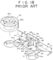
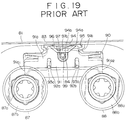
- FIG. 18 to 20 show that a case body of a tape cassette 81 comprises an upper case half 82 and a lower case half 83. Holes 84 are formed in the upper case half 82 and the lower case half 83 and a locking member 91 is provided in the lower case half 83. An unlocking pin 99 engages the locking member 91 when inserted through the hole 84 in the case body of the tape cassette 81 and shifts the locking member 91.
- a side of the case body of the tape cassette 81 nearer to a recording/reproducing head will be referred to as "the front”
- a side of the case body farther from the recording/reproducing head will be referred to as "the rear”.
- a substantially rectangular recess 90 is formed in the bottom wall of the lower case half 83 of the case body of the tape cassette 81 in the middle portion of the bottom wall and near the rear side of the case body of the tape cassette 81, and the locking member 91 is provided in the recess 90 and can be moved toward and away from the front, namely, toward and away from the spools 87 and 88.
- the locking member 91 has a flat body 91 a seated on the bottom surface of the recess 90, and a vertical projection 91 b standing upright from the rear portion of the flat body 91 a .
- the flat body 91 a is provided with a pair of fingers 91 a 1 and 91 a 2 projecting from the opposite ends of the front side thereof so as to correspond to the spools 87 and 88, respectively.
- Each spool 87, 88 has an inner spool 87 a , 88 a which receives a spool driving shaft therethrough, and an outer spool 87 b , 88 b engaged on the inner spool 87 a , 88 a for axial movement relative to the inner spool 87 a , 88 a and restrained from turning relative to the inner spool 87 a , 88 a .
- the fingers 91 a 1 and 91 a 2 of the locking member 91 can be pressed against portions of the circumferences of the inner spools 87 a and 88 a projecting from the lower surfaces of the outer spools 87 b and 88 b , respectively.
- a pair of guide slots 92 a and 92 b are formed in the front side of the middle portion of the flat body 91 a , and guide pins 93 a and 93 b project from the bottom surface of the recess 90 at positions respectively corresponding to the guide slots 92 a and 92 b .
- the guide pins 93 a and 93 b are received respectively in the guide slots 92 a and 92 b to guide the locking member 91 for movement in limited directions.
- a flat spring 94 for biasing the locking member 91 is disposed behind the locking member 91.
- the flat spring 94 has a main body 94 a , and an arm 94 b formed by raising a middle portion of the main body 94 a .
- the main body 94 a is fitted in a spring pocket 95 formed on the inner surface of the back wall of the lower case half 83, and the extremity of the arm 94 b is received in a recess 96 formed in the back surface of the vertical projection 91 b to bias the locking member 91 continuously toward the front side of the tape cassette, namely, in a direction to press the fingers 91 a 1 and 91 a 2 against the circumferences of the inner spools 87 a and 88 a .
- the locking member 91 is provided in the middle portion of the front surface of its vertical projection 91 b with a triangular protrusion 97 to disengage the locking member 91 from the inner spools 87 a and 88 a .
- the triangular protrusion 97 has inclined surfaces 97 a and 97 b symmetrically descending in opposite directions, respectively, from the apex thereof.
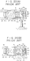
- the unlocking pin 99 received through the hole 84 of either the upper case half 82 or the lower case half 83 into the case body engages the inclined surface 97 a or 97 b of the triangular protrusion 97 to unlock the spools 87 and 88 by shifting the locking member 91 toward the rear side of the tape cassette
- the fingers 91 a 1 and 91 a 2 are pressed against the circumferences of the inner spools 87 a and 88 a by the resilience of the flat spring 94 as shown in Figure 20(A) and as indicated by alternate long and short dash lines in Figure 19 to lock the spools 87 and 88, so that the spools 87 and 88 are unable to turn even if shock forces are applied to the tape cassette 81.
- the unlocking pin 99 of the recording/reproducing apparatus enters the tape cassette 81 through the hole 84 as shown in Figure 20(B) and shifts the locking member 91 toward the rear of the tape cassette 81 to a position indicated by continuous lines in Figure 19 to unlock the spools 87 and 88 by separating the fingers 91 a 1 and 91 a 2 from the inner spools 87 a and 88 a .
- This conventional locking mechanism has the following problems, which will be described hereinafter with reference to Figures 21 to 26.
- Slackening of the tape T due to the rattling of the tape cassette 81 may be obviated by guiding the locking member 91 so that the locking member 91 is translated perfectly.
- the lighter one of the spools 87 and 88 can be unlocked when the tape cassette 81 is rattled.
- the arm 94 b of the flat spring 94 tending to spring toward the front of the tape cassette 81 must be strained by the locking member 91 in a direction, namely, toward the rear of the tape cassette 81, opposite the direction in which the arm 94 b tends to spring in putting the flat spring 94 in the lower case half 83 or in unlocking the spools 87 and 88, the stress induced in the flat spring 94 increases to cause the flat spring 94 to spring up or to tilt, which is highly likely to make normal spool locking action of the locking member 91 impossible.
- a tape cassette comprising: a case body having an opening in a front side thereof, and comprising an upper case half and a lower case half; a pair of spools on which a tape can be wound, supported for rotation within the case body, and provided respectively with toothed portions; a locking member slidable on the inner surface of a bottom wall of the lower case half within the case body toward and within the case body, and provided with locking fingers to be brought into engagement respectively with the toothed portions of the spools; and a spring means acting on the locking member to bias the locking member toward the rear of the case body; in which the locking member is provided with a cam portion having inclined surfaces sloping in opposite directions with respect to the thickness of the case body, one or other of the inclined surfaces of the cam portion of the locking member is engaged by a positioning pin of recording/reproducing apparatus when the tape cassette is loaded onto recording/reproducing apparatus, the locking member is moved against the resilience of the spring means toward the front of the case body by the positioning pin engaging one or
- the locking member is brought into contact with the circumferences of the spools from the front of the tape cassette to lock the spools, and the locking member is shifted toward the front of the tape cassette when the pin engages the cam portion to unlock the spools.
- the locking member presses the pair of spools of the tape cassette from the front of the tape cassette toward the rear of the cassette, namely, in a direction to tighten the tape so that slackening of the tape can be prevented. Since the locking member is moved toward the front of the tape cassette to unlock the spools, any additional space for the movement of the locking member need not be formed in the rear of the tape cassette, and unnecessary friction between the unlocking pin and the triangular cam portion can be obviated in ejecting the tape cassette from the recording/reproducing apparatus.
- a tape cassette in a first embodiment according to the invention will be described hereinafter with reference to Figures 1 to 10.
- the tape cassette 1 in the first embodiment is a very small tape cassette.
- the tape cassette 1 comprises a case body containing a magnetic tape T for recording, for example, PCM signals thereon, and constructed by fastening an upper case half 2 and a lower case half 3 together with screws 4, and a lid 6 pivotally joined to the case body so as to cover a front opening 5 formed at the front of the case body.
- a pair of spools 7 and 8 are disposed within the case body of the tape cassette 1, namely, within a space defined by the upper case half 2 and the lower case half 3, at positions corresponding to holes 2 a and 2 b (and 3 a and 3 b ) for receiving spool driving shafts, respectively, and the magnetic tape T is wound on the spools 7 and 8.
- a portion of the magnetic tape T is extended tautly between pinch rollers 9 and 10 serving also as guide rollers disposed on the opposite sides of the front opening 5 so as to be exposed through the front opening 5.
- Erase disable mechanisms 12 and 13 to prevent accidental erase of signals recorded on the magnetic tape T are formed on the opposite ends of the rear of the case body of the tape cassette 1 across the upper case half 2 and the lower case half 3.
- Positioning holes 14 and 15 are formed at positions near the front and rear, respectively, of the middle portion of the case body in each of the upper and lower walls of the case body, and positioning holes 16 and 17 are formed at the opposite ends, respectively, of the rear portion near the rear of the case body in each of the upper and lower walls of the cassette.
- a plurality of detection holes 18 and 19 are formed in the case body along the rear side thereof.
- Gripping portions 20 and 21 are formed in the rear portions of the opposite side surfaces of the case body of the tape cassette 1.
- the lid 6 for closing the front opening 5 of the case body is provided in its front surface with a longitudinal guide groove 22, and recesses 23 for a changer.
- Windows 2 a and 3 c of a transparent resin are formed in the middle portions of the upper wall of the upper case half 2 and the lower wall of the lower case half 3, respectively, to enable determination of the amount of the magnetic tape T on the spools 7 and 8 from outside the case body of the tape cassette.
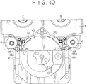
- the magnetic tape T contained in the case body is subjected to a helical scanning operation of a rotary head for recording or reproducing operation.
- a rotary head 41 rotates about an axis inclined at a predetermined angle to the axis of a head drum 42.
- the magnetic tape T extending along the front opening 5 is wound around a portion of the circumference of the head drum 42 exposed within the tape cassette 1.
- inclined tracks obliquely extending across the magnetic tape T are formed on the magnetic tape T.
- a pair of tape guide member 24 and 25 inclined respectively in opposite directions are disposed in the space for receiving a portion of the head drum 42 so as to be able to swing and to move laterally respectively on the inner sides of the pinch rollers 9 and 10 to ensure that the magnetic tape T slides helically along the head drum 42. Therefore, when the head drum 42 is inserted through the front opening 5 in the tape cassette 1, the tape guide members 24 and 25 are in contact with the circumference of the head drum 42 as shown in Figure 10 to guide the magnetic tape T by holding the magnetic tape T on the circumference of the head drum 42.
- the head drum 42 is provided on its opposite sides with wing guides 43 and 44 respectively supporting rollers 43 a and 44 a to be inserted between the pinch roller 9 and the tape guide 24 and between the pinch roller 10 and the tape guide 25, respectively.
- the magnetic tape T is pressed against the tape guide members 24 and 25 by the rollers 43 a and 44 a .
- the wing guides 43, 44 are inserted through the front opening 5 in the case body of the tape cassette 1 and are positioned between a respective support member 26, 27 and a respective guide 28, 29 disposed between the support member 26, 27 and the pinch roller 9, 10.
- each spool 7, 8 comprises an inner spool 7 a , 8 a that engages the spool driving shaft, and an outer spool 7 b , 8 b engaged on the inner spool 7 a , 8 a for axial movement thereon and restrained from rotation relative to the inner spool 7 a , 8 a .
- the inner spool 7 a , 8 a has toothed portion 7 a 1, 8 a 1 projecting from the outer spool 7 b , 8 b toward the lower case half 3 and provided in its circumference with teeth.
- the tape cassette 1 is provided with a locking member 11 that engages the toothed portion 7 a 1 and 8 a 1 of the spools 7 and 8 to lock the spools 7 and 8 while the tape cassette 1 is not in use.
- a positioning pin 99 which serves also as an unlocking pin, is received through the positioning hole 15 into the case body and shifts the locking member 11 in an unlocking direction to release the spools 7 and 8.
- the locking member 11 is placed in a recess 3 e formed in the lower case half 3.
- the locking member 11 has locking fingers 11 a 1 and 11 a 2 which engage the toothed portions 7 a 1 and 8 a 1 of the inner spools 7 a and 8 a to lock the spools 7 and 8, spring holding portions 11 b provided with holding lugs formed in a zig-zag arrangment to hold a locking spring 11 c fixedly, such as a stainless steel wire, with lugs, and a cam portion 11 d having inclined surfaces 11 d 1 and 11 d 2 sloping in opposite directions with respect to the direction of the thickness of the case body of the tape cassette 1 as shown in Figure 1(B).
- the locking member 11 is provided in its middle portion corresponding to the windows 2 c and 3 c of the case halves 2 and 3 with an opening 11 e .
- the opening 11 e is formed of a size that leaves the windows 2 c and 3 c open regardless of the position of the locking member 11.
- a guide pin 3 f projecting from the wall of the lower case half 3 is set in a guide slot 11 f formed in the locking member 11 to guide the locking member for movement between a locking position and an unlocking position and to restrain the locking member 11 from lateral movement.
- a holding finger 2 e projecting from the inner surface of the upper wall of the upper case half 2 toward the lower case half 3 is in contact with the upper end of the guide pin 3 f to prevent the locking member 11 falling off the guide pin 3 f .
- the locking member 11 has a slot 11 g comprising a taper portion 11 g 1 and a U-shaped portion 11 g 2 connected to the taper portion 11 g 1.
- a guide pin 3 g projecting from the bottom wall of the lower case half 3 is received in the guide slot 11 g .
- the guide pin 3 g engages the U-shaped portion 11 g 2 to restrain the locking member 11 from lateral movement.
- the locking member 11 is formed, to obtain resistance to abrasion by the positioning pin 99 (a metal pin, such as a stainless steel pin) of the recording/reproducing apparatus and sliding along the inner surface of the bottom wall of the lower case half 3, of an engineering plastics, such as POM.
- a metal pin such as a stainless steel pin
- the positioning pin 99 is received through one or other of the positioning holes 15 of the upper case half 2 and the lower case half 3 into the case body to locate the tape cassette 1 in the recording/reproducing apparatus and to unlock the spools 7 and 8 as shown in Figure 5.
- the locking member 11 Since the inclined surfaces 11 d 1 and 11 d 2 slope in opposite directions with respect to the direction of extension of the axes of the positioning holes 15 of the case halves 2 and 3 to form a V-shaped surface, the locking member 11 is moved against the resilience of the locking spring 11 c toward the front of the tape cassette 1, by the positioning pin 99 engaging one of the inclined surfaces 11 d 1 and 11 d 2 of the cam portion 11 d of the locking member 11, to an unlocking position shown in Figures 5 and 6. This movement of the locking member 11 is guided by the guide pin 3 f received in the guide slot 11 f . Consequently, the locking fingers 11 a 1 and 11 a 2 are separated from the toothed portions 7 a 1 and 8 a 1 to enable the spools 7 and 8 to rotate.
- the locking member 11 When the tape cassette 1 set in a locked state by the locking member 11 as shown in Figure 2 is loaded on the recording/reproducing apparatus, the locking member 11 is moved in the foregoing manner to set the tape cassette 1 to an unlocked state as shown in Figure 6.
- the locking member 11 When the tape cassette 1 is ejected from the recording/reproducing apparatus and the positioning pin 99 leaves the positioning hole 15, the locking member 11 is returned to the locking position as shown in Figure 2 to lock the spools 7 and 8.
- the guide pin 3 g projecting from the inner surface of the wall of the lower case half 3 is outside the U-shaped portion 11 g 2 of the guide slot 11 g .
- the guide pin 3 g moves into the U-shaped portion 11 g 2.
- the locking member 11 at the locking position is restrained from lateral movement only by the guide pin 3 f engaging the guide slot 11 f
- the locking member 11 at the unlocking position is restrained from lateral movement by both the guide pin 3 f engaging the guide slot 11 f and the guide pin 3 g received in the U-shaped portion 11 g 2 of the guide slot 11 g .
- the locking member 11 set at the locking position is able to turn slightly on the guide pin 3 f to enable the locking fingers 11 a 1 and 11 a 2 to engage the inner spools 7 a and 8 a properly.
- the locking member 11 is translated because the locking member 11 is restrained from lateral movement by both the guide pins 3 f and 3 g .
- a clearance C is formed between the locking member 11 and the walls defining the recess 3 e of the lower case half 3.
- the locking fingers 11 a 1 and 11 a 2 of the locking member 11 engage the toothed portions 7 a 1 and 8 a 1 of the inner spools 7 a and 8 a at positions on the outer sides of the diameters of the spools 7 and 8 parallel to a line perpendicular to a line joining the centres of the guide pins 3 f and 3 g , respectively.
- the locking spring 3 c is strained slightly in a gentle convex shape protruding toward the rear of the tape cassette 1 by the projection 3 d in the locking state as shown in Figure 2.
- the locking member 11 is urged continuously toward the rear of the tape cassette 1.
- the spool locking mechanism of the tape cassette 1 in this embodiment is thus constructed so that the locking fingers 11 a 1 and 11 a 2 biased toward the rear of the tape cassette 1 so as to engage the toothed portions 7 a 1 and 8 a 1 of the inner spools 7 a and 8 a are separated from the toothed portions 7 a 1 and 8 a 1 to unlock the spools 7 and 8 by pushing the locking member 11 toward the front of the tape cassette 1 with the positioning pin 99 received in the tape cassette 1 through the positioning hole 15 formed near the rear of the tape cassette 1.
- the positioning pin 99 received through the positioning hole 15 into the tape cassette 1 shifts the locking member toward the front of the tape cassette 1 in unlocking the spools 7 and 8.
- This shifting direction is reversed compared with the direction in which the locking member of a conventional tape cassette is shifted. Therefore, any space for the movement of the locking member 11 toward the rear of the tape cassette 1 need not be formed between the positioning hole 15 and the rear of the tape cassette 1, and hence the positioning hole 15 may be contiguous with the rear of the tape cassette. Accordingly, a wide area is available in each of the upper and lower surfaces of the tape cassette 1 for applying a label to the tape cassette 1, which in particularly effective when the tape cassette is a very small one.
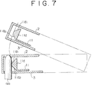
- the positioning pin 99 does not interfere with the movement of the apex of the cam portion 11, namely, the junction of the inclined surfaces 11 d 1 and 11 d 2, along a path indicated by alternate long and short dash line in Figure 7 and the locking member 11 is not moved toward the front of the tape cassette 1 beyond the unlocking position. Accordingly, unnecessary resistance obstructing the ejection of the tape cassette 1 does not act on the tape cassette 1 in separating the tape cassette 1 from the positioning pin 99.
- the width L2 ( Figure 1(B)) of the locking member 11, ie the dimension of the locking member 11 in the direction of movement of the locking member 11, is sufficiently long as compared with the height H2 ( Figure 1(B)) of the locking member 11 corresponding to the thickness of the cam portion 11 d . Therefore, the locking member 11 will not be tilted from a vertical direction relative to the upper case half 2 and the lower case half 3, and hence the spool locking action and the spool unlocking action of the locking member 11 will not be obstructed by undesirable friction between the locking member 11 and the lower case half 3.
- the locking member 11 In changing the tape cassette 1 from the unlocking state to the locking state by separating the same from the positioning pin 99, the locking member 11 is moved toward the rear of the tape cassette 1 and set at the locking position by the resilience of the locking spring 11 c and, consequently, the spools 7 and 8 are dislocated slightly toward the rear by the pressure applied thereto by the locking member 1.
- the magnetic tape T is not slackened in locking the spools 7 and 8, because the spools 7 and 8 are shifted, pulling the magnetic tape T.
- the locking member 11 is able to turn slightly on the guide pin 3 f positioned nearer to the front side of the tape cassette 1 than the locking fingers 11 a 1 and 11 a 2 in locking the spools 7 and 8. Therefore, the locking fingers 11 a 1 and 11 a 2 are able to engage the corresponding inner spools 7 a and 8 a differentially; that is, the resillence of the locking spring 11 c strained by the guide pin 3 f is distributed properly to the point of engagement of the locking finger 11 a 1 and the toothed portion 7 a 1 of the inner spool 7a and the point of engagement of the locking finger 11 a 2 and the toothed portion 8 a 1 of the inner spool 8 a on the opposite sides of the guide pin 3 f .
- the centre axis of the locking member 11 is not necessarily parallel to a line passing the respective centres of the guide pins 3 f and 3 g when the locking member 11 is held in the locking state, no problem arises in holding the locking member 11 at the unlocking position and in shifting the locking member 11, because the locking member 11 is restrained from lateral movement by the guide pin 3 f engaging the guide slot 11 f , and the guide pin 3 g engaging the U-shaped portion 11 g 2 when the guide member 11 is at the unlocking position.
- guide pins on the locking member 11 and to form guide slots in the lower case half 3 as a means for guiding the locking member 11 for sliding movement and for restraining the locking member 11 from lateral movement.
- the locking member 11 since the locking member 11 is moved toward the front of the tape cassette 1 in unlocking the spools 7 and 8, and pressure is applied continuously to the spools 7 and 8 so as to bias the spools 7 and 8 toward the rear of the tape cassette 1 by the locking member 11 in the locking state, the spools 7 and 8 are unable to move instantaneously toward the rear of the tape cassette 1 even if an impact acting toward the front is applied to the tape cassette 1 and hence the spools 7 and 8 are not pulled for rotation by the magnetic tape T.
- the magnetic tape T will not be unwound from the spools 7 and 8 and not caused to slacken by an impact acting on the rear of the tape cassette 1.
- the locking member 11 is formed so that the locking fingers 11 a 1 and 11 a 2 engaging the toothed portions 7 a 1 and 8 a 1 of the spools 7 and 8 from the front side of the tape cassette 1 are disengaged from the toothed portions 7 a 1 and 8 a 1 of the spools 7 and 8 with the positioning pin 99 received into the tape cassette 1 through the positioning hole 15 formed near the rear of the tape cassette 1, the locking member 11 covers the window 3 c of the lower case half 3. Therefore, the locking member 11 is provided with the opening 11 e to enable determination of the amount of the magnetic tape T on the spools 7 and 8 through the window 3 c of the lower case half 3.
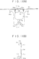
- a tape cassette 1A of a second embodiment of a tape cassette according to the invention is described hereinafter with reference to Figures 11 to 13. Parts like or corresponding to those shown in Figures 2 and 5 are denoted by the same reference characters.
- Locking fingers 31 a 1 and 31 a 2 which engage the toothed portions 7 a 1 and 8 a 1 of the inner spools 7 a and 8 a of the spools 7 and 8 to lock the spools 7 and 8, a cam portion 31 d having inclined surfaces 31 d 1 and 31 d 2 sloping in opposite directions to form a V-shaped surface with respect to the direction of thickness of the tape cassette 1A, and an opening 31 e corresponding to windows 2 c and 3 c formed in an upper case half 2 and a lower case half 3A of a locking member 31 are substantially the same as those of the locking member 11 employed in the first embodiment.
- the lower case half 3A similarly to the lower case half 3 of the first embodiment is provided with the guide pins 3 f and 3 g projecting form the inner surface of the bottom wall thereof, and the locking member 31, similarly to the locking member 11 of the first embodiment, is provided with guide slots 31 f and 31 g respectively for receiving the guide pins 3 f and 3 g .
- the locking member 31 has only one spring holding portion 31 b formed at the middle of the upper side, as viewed in Figure 11(A), thereof.
- the spring holding portion 31 b has L-shaped lugs 31 b 1 and 31 b 2 fixedly holding a locking spring 31 c , such as a stainless steel wire.
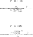
- the locking spring 31 c extends laterally in opposite directions from the spring holding portion 31 b beyond the opposite lateral sides of the locking member 11.
- the opposite ends of the locking spring 31 c rest respectively on steps 3 h 1 and 3 h 2 formed on the lower case half 3A as shown in Figure 12.
- the locking spring 31 c having the opposite ends resting on the steps 3 h 1 and 3 h 2 is strained so as to be convex toward the front of the tape cassette 1A to bias the locking member 31 toward the rear of the tape cassette 1A. Therefore, in the normal state, namely, while the tape cassette 1A is not in use, the locking fingers 31 a 1 and 31 a 2 are in engagement with the toothed portions 7 a 1 and 8 a 1 of the inner spools 7 a and 8 a as shown in Figure 12 to lock the spools 7 and 8.
- the employment of the locking springs 11 c and 31 c having the shape of a wire in the biasing means for biasing the locking members 11 and 31 toward the rear of the tape cassettes 1 and 1A enables the biasing means to be formed in a relatively small (thin) construction, which contributes to forming the tape cassettes 1 and 1A in a relatively small construction.
- the locking springs 11 c and 31 c having the shape of a relatively long, substantially straight wire are highly resistant to setting and durable to flexure.
- the locking members 11 and 31 are positioned so that the locking springs 11 c and 31 c extend in a gentle curve, and the locking springs 11 c and 31 c are strained further in unlocking the spools. That is, the locking spring 11 c employed in the first embodiment is strained continuously so as to extend in a convex curve protruding toward the rear of the tape cassette 1, and the locking spring 31 c employed in the second embodiment is strained continuously so as to extend in a convex curve protruding toward the front of the tape cassette 1A.
- the locking springs 11 c and 31 c are strained always in a fixed direction, the locking springs 11 c and 31 c neither bend back nor spring in putting the locking springs 11 c and 31 c in the case bodies of the tape cassettes 1 and 1A or in shifting the locking members 11 and 31. Furthermore, even if the locking springs 11 c and 31 c have a square cross-section instead of a circular cross-section or the same are flat springs, the locking springs 11 c and 31 c will not fall down. Accordingly, the locking members 11 and 31 can easily be put in the case bodies of the tape cassettes 1 and 1A, and the locking members 11 and 31 are able to slide stably.
- the opening 11 e or 31 e formed in the locking member 11, 31 at a position corresponding to the windows 3 c of the lower case half 3, 3A causes the portions of the locking member 11, 31 extending on the opposite sides of the opening 11 e , 31 e to be thin, which is somewhat disadvantageous to the rigidity of the locking member 11, 31. Furthermore, the size, shape and position of the windows 3 c of the upper case half 2 and the lower case half 3, 3A are dependent on the size, shape and position of the opening 11 e , 31 e .
- a tape cassette according to a third embodiment of the invention will be described hereinafter.
- the tape cassette of the third embodiment as shown in Figures 14(A), 14(B) and 14(C) and is provided with a locking member 61 formed of a transparent material but has no opening corresponding to the window 3 c of the lower case half 3.
- the locking member 61 has locking fingers 61 a 1 and 61 a 2, spring holding portions 61 b provided with holding lugs formed in a zig-zag arrangement and fixedly holding a locking spring 61 c , a cam portion 61 d having inclined surfaces 61 d 1 and 61 d 2, and guide slots 61 f and 61 g .
- the construction and functions of the locking member 61 are the same as those of the locking member 11 shown in Figure 1 and hence further description thereof will be omitted.
- the locking member 61 can have sufficiently high rigidity and can enable the respective windows 2 c and 3 c of the upper case half 2 and the lower case half 3 to be formed to an optimum size and an optimum shape at an optimum position.
- a tape cassette according to a fourth embodiment of the Invention has a locking member 71 capable of solving problems in the strength thereof and in the design of the windows 2 c and 3 c and is shown in Figures 15(A), 15(B), 15(C), Figure 16 and Figure 17.
- the locking member 71 has spring holding portions 71 b having lugs formed in a zig-zag arrangement to hold a locking spring 71 c , and a cam portion 71 d having inclined surfaces 71 d 1 and 71 d 2, which are similar to those of the locking member 11 employed in the first embodiment.
- the locking member 71 is different in shape from the locking member 11.
- the locking member 71 has lateral curved positions 71 h 1 and 71 h 2 bulging in opposite directions and defining a middle opening 71 e .
- Locking fingers 71 a 1 and 71 a 2 are formed on the inner side of a portion interconnecting the lateral curved portions 71 h 1 and 71 h 2.
- the locking member 71 is provided with guide slots 71 f and 71 g respectively to receive the guide pins 3 f and 3 g formed on the lower case half 3.
- the locking member 71 is placed in the lower case half 3 with the locking fingers 71 a 1 and 71 a 2 engaging the toothed portions 7 a 1 and 8 a 1 of the inner spools 7 a and 8 a of spools 7 and 8 to lock the spools 7 and 8.
- the locking member 71 similarly to the locking member 11 employed in the first embodiment, is shifted to an unlocking position shown in Figure 17 by a positioning pin 99 which engages one or other of the inclined surface 71 d 1 and 71 d 2.
- the rigidity of the locking member 71 employed in the fourth embodiment is higher than those of the locking members employed in the first and second embodiments.
- the shape of the locking member 71 enables optimum determination of the size, shape and position of the windows 2 c and 3 c of the upper case half 2 and the lower case half 3.
Landscapes
- Automatic Tape Cassette Changers (AREA)
Applications Claiming Priority (2)
| Application Number | Priority Date | Filing Date | Title |
|---|---|---|---|
| JP3031362A JP3024227B2 (ja) | 1991-02-01 | 1991-02-01 | テープカセット |
| JP31362/91 | 1991-02-01 |
Publications (3)
| Publication Number | Publication Date |
|---|---|
| EP0497624A2 true EP0497624A2 (de) | 1992-08-05 |
| EP0497624A3 EP0497624A3 (en) | 1993-07-14 |
| EP0497624B1 EP0497624B1 (de) | 1996-09-25 |
Family
ID=12329133
Family Applications (1)
| Application Number | Title | Priority Date | Filing Date |
|---|---|---|---|
| EP92300864A Expired - Lifetime EP0497624B1 (de) | 1991-02-01 | 1992-01-31 | Bandkassette |
Country Status (4)
| Country | Link |
|---|---|
| US (1) | US5276580A (de) |
| EP (1) | EP0497624B1 (de) |
| JP (1) | JP3024227B2 (de) |
| DE (1) | DE69213971T2 (de) |
Families Citing this family (1)
| Publication number | Priority date | Publication date | Assignee | Title |
|---|---|---|---|---|
| JP3473873B2 (ja) * | 1995-03-23 | 2003-12-08 | 富士写真フイルム株式会社 | 磁気テープカセット |
Citations (8)
| Publication number | Priority date | Publication date | Assignee | Title |
|---|---|---|---|---|
| US3259331A (en) * | 1963-08-01 | 1966-07-05 | Rca Corp | Brake member for a tape cartridge |
| US4029268A (en) * | 1974-09-28 | 1977-06-14 | Basf Aktiengesellschaft | Tape recorder and magnetic tape cassette |
| JPS57147172A (en) * | 1981-03-09 | 1982-09-10 | Sony Corp | Tape cassette |
| JPS6057586A (ja) * | 1983-09-07 | 1985-04-03 | Matsushita Electric Ind Co Ltd | テ−プカセツト |
| EP0228600A1 (de) * | 1985-12-06 | 1987-07-15 | Hitachi Maxell Ltd. | Bandkassette |
| EP0411622A2 (de) * | 1989-08-04 | 1991-02-06 | Shape Inc. | Einheitliche, elastische Spulenverriegelungsvorrichtung für Videokassette |
| EP0431914A2 (de) * | 1989-12-06 | 1991-06-12 | Sony Corporation | Magnetbandkassetten |
| EP0490610A1 (de) * | 1990-12-10 | 1992-06-17 | Sony Corporation | Bandkassette |
Family Cites Families (13)
| Publication number | Priority date | Publication date | Assignee | Title |
|---|---|---|---|---|
| JPS60187982A (ja) * | 1984-03-07 | 1985-09-25 | Sony Corp | テ−プカセット |
| JPH0721952B2 (ja) * | 1984-05-30 | 1995-03-08 | 日立マクセル株式会社 | テ−プカ−トリツジ |
| JPS6145784U (ja) * | 1984-08-27 | 1986-03-26 | 富士写真フイルム株式会社 | 磁気テ−プカセツト |
| US4635879A (en) * | 1984-09-12 | 1987-01-13 | Hitachi Maxell, Ltd. | Tape cassette |
| JPH0445183Y2 (de) * | 1984-09-14 | 1992-10-23 | ||
| JPH0348785Y2 (de) * | 1985-10-18 | 1991-10-17 | ||
| US4789113A (en) * | 1986-10-20 | 1988-12-06 | Fuji Photo Film Co., Ltd. | Hub locking mechanism in a magnetic tape cassette |
| DE3735671A1 (de) * | 1987-10-22 | 1989-05-03 | Agfa Gevaert Ag | Magnetbandcassette |
| JPH01107078U (de) * | 1987-12-29 | 1989-07-19 | ||
| DE8805416U1 (de) * | 1988-04-23 | 1988-08-18 | Basf Ag, 6700 Ludwigshafen, De | |
| KR940009172B1 (ko) * | 1988-10-07 | 1994-10-01 | 주식회사 에스케이씨 | 테이프 카트리지 |
| US4969611A (en) * | 1988-10-13 | 1990-11-13 | Fuji Photo Film Co., Ltd. | Magnetic tape cassette |
| JPH03290884A (ja) * | 1990-04-09 | 1991-12-20 | Sony Corp | テープカセットのリールロック機構 |
-
1991
- 1991-02-01 JP JP3031362A patent/JP3024227B2/ja not_active Expired - Fee Related
-
1992
- 1992-01-29 US US07/827,933 patent/US5276580A/en not_active Expired - Fee Related
- 1992-01-31 EP EP92300864A patent/EP0497624B1/de not_active Expired - Lifetime
- 1992-01-31 DE DE69213971T patent/DE69213971T2/de not_active Expired - Fee Related
Patent Citations (8)
| Publication number | Priority date | Publication date | Assignee | Title |
|---|---|---|---|---|
| US3259331A (en) * | 1963-08-01 | 1966-07-05 | Rca Corp | Brake member for a tape cartridge |
| US4029268A (en) * | 1974-09-28 | 1977-06-14 | Basf Aktiengesellschaft | Tape recorder and magnetic tape cassette |
| JPS57147172A (en) * | 1981-03-09 | 1982-09-10 | Sony Corp | Tape cassette |
| JPS6057586A (ja) * | 1983-09-07 | 1985-04-03 | Matsushita Electric Ind Co Ltd | テ−プカセツト |
| EP0228600A1 (de) * | 1985-12-06 | 1987-07-15 | Hitachi Maxell Ltd. | Bandkassette |
| EP0411622A2 (de) * | 1989-08-04 | 1991-02-06 | Shape Inc. | Einheitliche, elastische Spulenverriegelungsvorrichtung für Videokassette |
| EP0431914A2 (de) * | 1989-12-06 | 1991-06-12 | Sony Corporation | Magnetbandkassetten |
| EP0490610A1 (de) * | 1990-12-10 | 1992-06-17 | Sony Corporation | Bandkassette |
Non-Patent Citations (3)
| Title |
|---|
| PATENT ABSTRACTS OF JAPAN vol. 009, no. 190 (P-378)7 August 1985 & JP-A-60 057 586 ( MATSUSHITA DENKI SANGYO KK ) 3 April 1985 * |
| PATENT ABSTRACTS OF JAPAN vol. 6, no. 252 (P-161)(1130) 10 December 1982 & JP-A-57 147 172 ( SONY K.K. ) 10 September 1982 * |
| PROCEEDINGS OF THE INSTITUTE OF ELECTRICAL ENGINEERS vol. 16, B, no. 14, 19 March 1956, NEW YORK, NY, USA pages 219 - 220 BURT AND ANDREWS 'A new magnetic recording system' * |
Also Published As
| Publication number | Publication date |
|---|---|
| EP0497624A3 (en) | 1993-07-14 |
| DE69213971D1 (de) | 1996-10-31 |
| US5276580A (en) | 1994-01-04 |
| EP0497624B1 (de) | 1996-09-25 |
| DE69213971T2 (de) | 1997-04-03 |
| JP3024227B2 (ja) | 2000-03-21 |
| JPH04356771A (ja) | 1992-12-10 |
Similar Documents
| Publication | Publication Date | Title |
|---|---|---|
| GB2124012A (en) | Disc cassette loading apparatus | |
| JPH0344857A (ja) | 磁気テープで信号の記録/再生を行うシステム及びそのようなシステムに使用される装置及びカセット | |
| CA2001678C (en) | Small and large cassette holder for tape recorder | |
| JPH06500522A (ja) | 磁気テープカセットの収容器 | |
| US5548577A (en) | Disc cartridge | |
| EP0497624A2 (de) | Bandkassette | |
| EP0580355B1 (de) | Bandkassette | |
| US6505788B1 (en) | Tape cassette | |
| KR0148625B1 (ko) | 기록재생장치의 카세트 로딩기구 | |
| EP0793231A2 (de) | Bandkassette | |
| KR100466472B1 (ko) | 크기가다른복수종류의카세트를장착할수있는카세트콘테이너 | |
| US5326046A (en) | Tape cassette with reel locking member supported for sliding movement by converging ribs | |
| EP0490610B1 (de) | Bandkassette | |
| CA2132822C (en) | Small and large cassette holder for tape recorder | |
| JP4090396B2 (ja) | 記録テープカートリッジ | |
| JP3433589B2 (ja) | 記録媒体装着装置 | |
| JP3024228B2 (ja) | テープカセット | |
| JP3097236B2 (ja) | テープカセット | |
| JP2976544B2 (ja) | テープカセット | |
| JP4017311B2 (ja) | 磁気テープカセット | |
| EP1008988A2 (de) | Aufzeichnungs- / Wiedergabegerät | |
| JPH04356776A (ja) | テープカセット | |
| JPH04356775A (ja) | テープカセット | |
| JPH097342A (ja) | テープカートリッジ | |
| JPH04356774A (ja) | テープカセット |
Legal Events
| Date | Code | Title | Description |
|---|---|---|---|
| PUAI | Public reference made under article 153(3) epc to a published international application that has entered the european phase |
Free format text: ORIGINAL CODE: 0009012 |
|
| AK | Designated contracting states |
Kind code of ref document: A2 Designated state(s): DE FR GB |
|
| PUAL | Search report despatched |
Free format text: ORIGINAL CODE: 0009013 |
|
| AK | Designated contracting states |
Kind code of ref document: A3 Designated state(s): DE FR GB |
|
| 17P | Request for examination filed |
Effective date: 19931118 |
|
| 17Q | First examination report despatched |
Effective date: 19950413 |
|
| GRAG | Despatch of communication of intention to grant |
Free format text: ORIGINAL CODE: EPIDOS AGRA |
|
| GRAH | Despatch of communication of intention to grant a patent |
Free format text: ORIGINAL CODE: EPIDOS IGRA |
|
| GRAH | Despatch of communication of intention to grant a patent |
Free format text: ORIGINAL CODE: EPIDOS IGRA |
|
| GRAA | (expected) grant |
Free format text: ORIGINAL CODE: 0009210 |
|
| AK | Designated contracting states |
Kind code of ref document: B1 Designated state(s): DE FR GB |
|
| REF | Corresponds to: |
Ref document number: 69213971 Country of ref document: DE Date of ref document: 19961031 |
|
| ET | Fr: translation filed | ||
| PLBE | No opposition filed within time limit |
Free format text: ORIGINAL CODE: 0009261 |
|
| STAA | Information on the status of an ep patent application or granted ep patent |
Free format text: STATUS: NO OPPOSITION FILED WITHIN TIME LIMIT |
|
| 26N | No opposition filed | ||
| REG | Reference to a national code |
Ref country code: GB Ref legal event code: IF02 |
|
| PGFP | Annual fee paid to national office [announced via postgrant information from national office to epo] |
Ref country code: FR Payment date: 20020110 Year of fee payment: 11 |
|
| PGFP | Annual fee paid to national office [announced via postgrant information from national office to epo] |
Ref country code: GB Payment date: 20020130 Year of fee payment: 11 |
|
| PGFP | Annual fee paid to national office [announced via postgrant information from national office to epo] |
Ref country code: DE Payment date: 20020227 Year of fee payment: 11 |
|
| PG25 | Lapsed in a contracting state [announced via postgrant information from national office to epo] |
Ref country code: GB Free format text: LAPSE BECAUSE OF NON-PAYMENT OF DUE FEES Effective date: 20030131 |
|
| PG25 | Lapsed in a contracting state [announced via postgrant information from national office to epo] |
Ref country code: DE Free format text: LAPSE BECAUSE OF NON-PAYMENT OF DUE FEES Effective date: 20030801 |
|
| GBPC | Gb: european patent ceased through non-payment of renewal fee | ||
| PG25 | Lapsed in a contracting state [announced via postgrant information from national office to epo] |
Ref country code: FR Free format text: LAPSE BECAUSE OF NON-PAYMENT OF DUE FEES Effective date: 20030930 |
|
| REG | Reference to a national code |
Ref country code: FR Ref legal event code: ST |