EP0497178A2 - Bildeingabegerät - Google Patents
Bildeingabegerät Download PDFInfo
- Publication number
- EP0497178A2 EP0497178A2 EP92100848A EP92100848A EP0497178A2 EP 0497178 A2 EP0497178 A2 EP 0497178A2 EP 92100848 A EP92100848 A EP 92100848A EP 92100848 A EP92100848 A EP 92100848A EP 0497178 A2 EP0497178 A2 EP 0497178A2
- Authority
- EP
- European Patent Office
- Prior art keywords
- image
- document
- images
- type display
- thin type
- Prior art date
- Legal status (The legal status is an assumption and is not a legal conclusion. Google has not performed a legal analysis and makes no representation as to the accuracy of the status listed.)
- Granted
Links
Images


Classifications
-
- H—ELECTRICITY
- H04—ELECTRIC COMMUNICATION TECHNIQUE
- H04N—PICTORIAL COMMUNICATION, e.g. TELEVISION
- H04N1/00—Scanning, transmission or reproduction of documents or the like, e.g. facsimile transmission; Details thereof
- H04N1/04—Scanning arrangements, i.e. arrangements for the displacement of active reading or reproducing elements relative to the original or reproducing medium, or vice versa
- H04N1/10—Scanning arrangements, i.e. arrangements for the displacement of active reading or reproducing elements relative to the original or reproducing medium, or vice versa using flat picture-bearing surfaces
- H04N1/107—Scanning arrangements, i.e. arrangements for the displacement of active reading or reproducing elements relative to the original or reproducing medium, or vice versa using flat picture-bearing surfaces with manual scanning
- H04N1/1072—Means for guiding the scanning, e.g. rules
-
- H—ELECTRICITY
- H04—ELECTRIC COMMUNICATION TECHNIQUE
- H04N—PICTORIAL COMMUNICATION, e.g. TELEVISION
- H04N1/00—Scanning, transmission or reproduction of documents or the like, e.g. facsimile transmission; Details thereof
- H04N1/04—Scanning arrangements, i.e. arrangements for the displacement of active reading or reproducing elements relative to the original or reproducing medium, or vice versa
- H04N1/10—Scanning arrangements, i.e. arrangements for the displacement of active reading or reproducing elements relative to the original or reproducing medium, or vice versa using flat picture-bearing surfaces
- H04N1/107—Scanning arrangements, i.e. arrangements for the displacement of active reading or reproducing elements relative to the original or reproducing medium, or vice versa using flat picture-bearing surfaces with manual scanning
-
- H—ELECTRICITY
- H04—ELECTRIC COMMUNICATION TECHNIQUE
- H04N—PICTORIAL COMMUNICATION, e.g. TELEVISION
- H04N1/00—Scanning, transmission or reproduction of documents or the like, e.g. facsimile transmission; Details thereof
- H04N1/04—Scanning arrangements, i.e. arrangements for the displacement of active reading or reproducing elements relative to the original or reproducing medium, or vice versa
- H04N1/10—Scanning arrangements, i.e. arrangements for the displacement of active reading or reproducing elements relative to the original or reproducing medium, or vice versa using flat picture-bearing surfaces
- H04N1/1013—Scanning arrangements, i.e. arrangements for the displacement of active reading or reproducing elements relative to the original or reproducing medium, or vice versa using flat picture-bearing surfaces with sub-scanning by translatory movement of at least a part of the main-scanning components
- H04N1/1017—Scanning arrangements, i.e. arrangements for the displacement of active reading or reproducing elements relative to the original or reproducing medium, or vice versa using flat picture-bearing surfaces with sub-scanning by translatory movement of at least a part of the main-scanning components the main-scanning components remaining positionally invariant with respect to one another in the sub-scanning direction
-
- H—ELECTRICITY
- H04—ELECTRIC COMMUNICATION TECHNIQUE
- H04N—PICTORIAL COMMUNICATION, e.g. TELEVISION
- H04N1/00—Scanning, transmission or reproduction of documents or the like, e.g. facsimile transmission; Details thereof
- H04N1/04—Scanning arrangements, i.e. arrangements for the displacement of active reading or reproducing elements relative to the original or reproducing medium, or vice versa
- H04N1/19—Scanning arrangements, i.e. arrangements for the displacement of active reading or reproducing elements relative to the original or reproducing medium, or vice versa using multi-element arrays
- H04N1/191—Scanning arrangements, i.e. arrangements for the displacement of active reading or reproducing elements relative to the original or reproducing medium, or vice versa using multi-element arrays the array comprising a one-dimensional [1D] array
- H04N1/192—Simultaneously or substantially simultaneously scanning picture elements on one main scanning line
- H04N1/193—Simultaneously or substantially simultaneously scanning picture elements on one main scanning line using electrically scanned linear arrays, e.g. linear CCD arrays
-
- H—ELECTRICITY
- H04—ELECTRIC COMMUNICATION TECHNIQUE
- H04N—PICTORIAL COMMUNICATION, e.g. TELEVISION
- H04N2201/00—Indexing scheme relating to scanning, transmission or reproduction of documents or the like, and to details thereof
- H04N2201/04—Scanning arrangements
- H04N2201/0402—Arrangements not specific to a particular one of the scanning methods covered by groups H04N1/04 - H04N1/207
- H04N2201/043—Viewing the scanned area
Definitions
- the present invention generally relates to an image inputting equipment to be used in office ⁇ automation apparatus for handling the images of facsimile, hand ⁇ fax, personal information terminal, image reader, image recognizing apparatus, optical character reader (OCR), digital duplicating machine or the like.
- OCR optical character reader
- an image ⁇ scanner a television camera (electronic camera) are now used as a means for converting image information into electric information.
- an optical character reader or a bar code ⁇ reader is provided for outputtng figures and characters with image inputs and processing being combined with each other. It is adapted to process the read digital image data to convert them into figures and character codes, which are outputted.
- the conventional image inputting equipment will be described hereinafter by way of an image ⁇ scanner which can handle multivalue images.
- the above described image ⁇ scanner is provided with an exposure portion for illuminating the document, a photo-electric converting portion for converting light to electricity, a document scanning portion for decomposing a document into picture elements, and so on.
- the image ⁇ scanner is adapted to convert into electric signals with a photosensor the reflection light from the document or the brightness of the transmission light so as to output them as digital image data for each picture element.
- image ⁇ scanners such as simple hand scanner, printer mounted scanner, facsimile type scanner, electronic camera type scanner, cylinder type scanner and duplicator type scanner and so on are provided as such image ⁇ scanners.
- FIG. 9 is a perspective view of a representative image reader of the above described duplicator type scanner.
- a reader 4 is composed of a light source 1, a lens ⁇ eye 2 and an image sensor ⁇ array 3 being integrally installed.
- the reader portion 4 has the light source 1, the lens ⁇ array 2 and the image sensor ⁇ array 3 arranged respectively in one row, which form a so-called line scanner.
- Light radiated from the above described light source 1 is reflected on the surfaces of the document 5 and becomes incident into the image sensor ⁇ array 3 through the lens ⁇ array 2 so that the digital image data of one scanning line portion are read.
- the reader portion 4 in an arrow direction, along the document, the image information of one sheet of the document is read.
- the digital image data are variably processed by a CPU (Central Processing Unit).
- the read images are displayed on the CRT (Cathode ⁇ Ray ⁇ Tube), printed by a printer.
- the above described reader portion 4 and a display portion for a printer, CRT or the like are respectively composed as a separate unit. Since the reader portion 4 and the display portion are positioned away from each other, the comparison between the document and the reading images of the document cannot be effected with real time. Accordingly, the same document often has to be read for resolution comparison, the light, shade level adjustment, and so on.
- the present invention has been developed with a view to substantially eliminating the above discussed drawbacks inherent in the prior art, and has for its essential object to provide an improved image inputting equipment.
- Another important object of the present invention is to provide an improved image inputting equipment capable of comparison, with real time, between the document and the images of the document.
- an image inputting equipment which includes an image inputting portion for scanning documents to read the image information on the above described documents, a transmission thin type display, an image display means for displaying the images of the above described document on the above described transmission thin type display in accordance with the image information on the document read by the above described image input portion, and is characterized in that a position detecting means for detecting a position on the above described transmission thin type display of the above described image input portion so as to output the positional information, the above described image inputting portion is disposed for its free sliding operation along the reverse face of the above described transmission thin type display so as to scan the document disposed opposite to the reverse face of the above described transmission thin type display, the above described image displaying means for displaying the images of the document on the above described transmission thin type display so that the images and the document corresponding to the images may be visually superposed in accordance with the positional information outputted from the above described position detecting means and the image information read by the above described image in
- the image input portion is slid along the reverse face of the transmission thin type display, the above described document is scanned and the image information on the above described document is read.
- the position on the transmission thin type display of the above described image inputting portion is detected by the position detecting means so as to output the position information.
- the images of the above described document are displayed on the above described transmission thin type display so that the images and the document corresponding to the images may be visually superposed in accordance with the position information outputted from the above described position detecting means and the image information read by the above described picture inputting portion, by the image displaying means.
- the images of the document scanned, read already by the image input portion are displayed on the above described transmission thin type display so that they may be superposed on the document corresponding to the images.
- the unscanned portions of the above described document can be seen through the transmission of the location where the images are not displayed yet on the above described transmission thin type display.
- the simultaneous comparing operation between the document and the images of the document may be effected so that the images may be easily checked, corrected.
- FIG. 1 an outer appearance view of an image inputting equipment in the present embodiment.
- an A4 size of tablet shaped image inputting equipment will be described hereinafter by way of example.
- the image inputting equipment is roughly composed of a transmission thin type display 11, an image inputting portion 12 mounted for its sliding operation on the reverse face of the transmission thin type display 11, a background cover 13 mounted for its free opening, closing operations on one side with a hinge on the above described transmission thin type display 11.
- Fig. 2 is a partial perspective view of the above described transmission thin type display 11 and the image inputting portion 12.
- the above described image inputting portion 12 is disposed as follows on the reverse face of the transmission thin type display 11 with the use of the line scanners as often seen in a duplicator type scanner. Namely, a horizontally extending groove 15 is provided in a frame 14 on the side with the above described hinge pivoting around the above described hinge, from two frames extending in the scanning direction of the image inputting portion 12, frames for fixing the periphery of the transmission thin type display 11.
- an approximately L-shaped scan lever 16 is provided at the above described one end of the image inputting portion 12 disposed vertically in the scanning direction with one end being inserted into the groove 15, the one end is coupled in the vertical direction to the above described one end of the image inputting portion 12.
- the bent portion 17 provided at the other end of the scan lever 16 is engaged for its free sliding operation with the scan guide 18 provided on the above described frame 14.
- the other side of the image inputting portion 12 is mounted for its free sliding operation on the frame 14' (see Fig. 1) on the above described hinge side.
- the image inputting portion 12 is disposed for its free sliding operation along the reverse face of the transmitting thin type display 11.
- the image inputting portion 12 can be slid by the sliding operation of the scan lever in an arrow mark direction with a finger being depressed against a slightly concave finger applying portion 19.
- Slits 20, 20, ... for position detection use are disposed at equal intervals in a position opposite to the above described one end of the image inputting portion 12 in the above described groove 15.
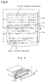
- Fig. 3 is a detailed view of the above described image inputting portion 12.
- Fig. 3 (a) is a sectional view of the image inputting portion 12 mounted on the frame 14 as described hereinabove.
- Fig. 3 (b) is a vertical sectional view of the image inputting portion 12 mounted on the frame 14.
- a light source array 21 composed of an LED (light emitting diode) and so on, and an image sensor ⁇ array 22 composed of a photoelectric converting element, a CCD (Charge Coupling Element) and so on are provided in the image inputting portion 12.
- the light source array 21 and the image sensor ⁇ array 22 are disposed across the full width of the document 23 along the longitudinal direction of the image inputting portion 12 and are formed a so-called line scanner, with the light emitting face of the light source array 21 and the light receiving face of the image sensor ⁇ array 22 being made opposite at a given angle ⁇ .
- the light radiated downwards from the light source array 21 is adapted to be reflected on the surfaces of the document 23 and be incident onto the light receiving face of the image sensor ⁇ array 22.
- a position detecting sensor 24 is mounted opposite to the slit 20 for position detecting use slit in a portion which is in the above described one end of the above described image inputting portion 12, and is within the groove 15 of the frame 14.
- the passing number of the slits 20 for the position detecting use caused through the movement of the image inputting portion 12 is counted in accordance with the light and darkness of the reflection light from the inner face of the groove 15 detected by the position detecting sensor 24 when the image inputting portion 12 has been slid towards the other end from one end of the groove 15.
- the above described position detecting means is composed of a slit 20 for the above described position detection use and the position detecting sensor 24.
- a transparent thin type display 11 in the present embodiment is composed of a liquid display (hereinafter referred to as LCD) whose outer appearance is shown in Fig. 4.
- the LCD panel 25 is composed so that a non-display picture element may become transparent without the use of the color filter.
- the above described LCD panel 25 is driven with such a LCD driving portion as shown in Fig. 5.
- a voltage corresponding to each picture element of the LCD panel 25 is retained in an X driver 28 when the digital image data of the one scanning line portion read from the frame memory 27 has been inputted into the X driver 28 under the control of the LCD controller 26. It is fed to each data line of the LCD panel 25.
- the voltage corresponding to the digital image signal is stored in all the picture elements on the scanning line to display the picture elements.
- the above described operation is sequentially performed with respect to all the scanning lines so as to display the images of one frame on the LCD panel 25.
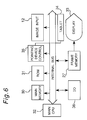
- Fig. 6 is a schematic block diagram of an entire image inputting equipment provided with the above described transmission thin type display 11 and the image inputting portion 12.
- the image inputting equipment has an image inputting portion 12 added to the normal microprocessor ⁇ system, with a function for handling the image being provided in each composing portion.
- a main memory 30 is composed of a DRAM (Dynamic ⁇ Random ⁇ Access ⁇ Memory), a SRAM (Static ⁇ Random ⁇ Access ⁇ Memory), pseudoSRAM or the like, with the read digital image data, the digital image data after the various processing and so on being accommodated in it.
- the control program for the main CPU use 32, various parameters and so on are accommodated in the ROM (Read ⁇ Only ⁇ Memory).
- the display portion 33 is composed of the above described LCD panel 25 which is the transmission thin type display 11 and the above described LCD driving portion in the present embodiment.
- the bit map ⁇ data of the display portion in the display portion 33 obtained in accordance with the digital image data accommodated in the above described main memory 30 are accommodated in the frame memory 27.
- the image inputting portion 12 is composed of a light array 21 and an image sensor ⁇ array 22 as described hereinabove.
- the image inputting proton 12 scan the document with a manual operation along the reverse face of the LCD panel 25 composing the display portion 33 as described hereinabove.
- a pointing ⁇ device control portion 35 displays a position, specified by a tablet portion 34, on the display portion 33 or the like in accordance with the positional information from the tablet portion 34 composed of a tablet and stylus.
- An I/O (Input output interface) 36 is an interface to peripheral apparatuses such as communication apparatus and so on which are options.
- An image inputting equipment of the above described construction reads a document to display it as follows. Open a transmission thin type display 11 composing the top cover of the above described image inputting equipment, and close the transmitting thin type display 11 with a document 23 being put on the back cover 13. The document 23 is grasped among the frames 14, 14' of the transmitting thin type display 11 and the back cover 13 as shown in Fig. 1. The image inputting portion 12 is positioned in one end portion of the transmission thin type display 11.
- Fig. 3 (a) lights radiated from the light source array 21 accommodated in the picture image inputting portion 12 are reflected on the surfaces of the document 23 and become incident into the image sensor ⁇ array 22.
- the image signals showing the light and darkness of the reflection light from the document inputted into the image sensor ⁇ array 22 are converted into electric signals by the image sensor ⁇ array 22.
- the digital image data of the first one scanning line portion are obtained and are accommodated in the main memory 30.
- the digital image data of one scanning line portion obtained at present by the positional information in accordance with the number ("0" in the first one scanning line) of the slits 20 for position detecting use detected by the positional detection sensor 24 is judged by a main CPU32 to be digital image data in accordance with the first one scanning line.
- the various processing of expansion, reduction or the like are applied by the main CPU32 upon the digital image data of the first one scanning line portion obtained, and are stored in the given address of the frame memory 27 in accordance with the above described position information.
- the digital image data of one portion stored in the frame memory 27 at the present time by the LCD controller is read with real time.
- the display is effected in the position the same as that of the image inputting portion 12 in the LCD panel (is a transmission thin type display 11 in Fig. 1 through Fig. 3, is a display portion 33 in Fig. 6).
- the image inputting portion 12 is slid in an arrow direction with a finger being pressed against the finger applying portion 19 of a scan lever 16 shown in Fig. 2.
- the number of the slits 20 for position detection use through the movement of the image inputting portion 12 is detected by the position detecting sensor 24 so that the position information of the image inputting portion 12 is obtained.
- the digital image data of the next one scanning line portion is obtained by the image inputting portion 12 in synchronous relation with the obtained position information and is accommodated in the main memory 30.
- the digital image data of one scanning line portion with the various processing being applied on it are stored in the given address of the frame memory 27.
- the digital image data stored at present are read from the frame memory 27.
- the next one scanning line portion of image is displayed with real time in the same position as the position of the image inputting portion 12 in the LCD panel 25.
- images (hereinafter, the read images displayed on the LCD panel 25 in this manner are called display images) are displayed through electric signals in a region (b) through which the image inputting portion 12 has already passed on the LCD panel 25, with a location of one scanning line (a) where the images are about to be read by the image inputting portion 12 being a boundary.
- the document 23 (hereinafter the images of the document directly seen through the transmission of the LCD panel 25 in this manner are called original images) are seen through the transmission of the region (c) through which the image inputting portion 23 has not passed yet.
- the size of the display resolution and the display image is properly set with respect to the digital image data read by the above described image inputting portion 12, so that the display images and the original images can be superposed in the above described region (b).
- One sheet of document can be made with the display images of the region (b) and the original images of the region (c).
- the display images to be displayed on the region (b) in the above described LCD panel 25 and the original images to be seen through the transmission of the region (c) can be seen simultaneously with the location of one scanning line (a) being a boundary, the document can be compared with real time with the reading images of the document.
- the resolution of the reading images, the emphasis degrees of the edges, and the light and shade degree can be known with a real time.
- the resolution comparison and the light shade level adjustment can be effected by one image reading operation.
- an image inputting portion 12 provided with a light source array 21, an image sensor ⁇ array 22 is arranged for its free sliding operation on the reverse face of the transmission thin type display 11 composed of an LCD panel 25 and so on.
- the images of the document 23 grasped among the frames 14, 14' of the transmission thin type display 11 and the back cover 13 are read by the sliding operation of the image inputting portion 21.
- the display images of the document 23 are displayed on the transmission thin type display 11 in accordance with the digital image data read in this manner.
- the display images to be displayed on the region (b) and the original image seen through the transmission of the region (c) in the LCD panel 25 can be seen at the same time with location of one scanning line (a) as the boundary.
- the document can be compared with real time with the read images of the document.
- the resolution comparison and the light, shade level adjustment can be effected by one time of image reading operation.
- the images of the read document are adapted to be displayed on the LCD panel 25.
- the above described image inputting apparatus can be used as follows.
- the images of the above described character recognition result are displayed in the region (e) through which the image inputting portion 12 has passed on the LCD panel 25 with the location of one running line (d) where the images of the hand-written characters at present are loaded by the image inputting portion 12 being provided as the boundary.
- the original images (namely, the hand-written characters on the document 37) of the document 37 are seen through the region (c) through which the image inputting portion 13 does not pass.
- the above described character recognition results can be checked/corrected with real time.
- a character recognition portion and a translation portion can be added as the above described processing portion.
- the characters of the sentences with source language described in the document are recognized in the character recognition portion.
- the recognition results are displayed on the LCD panel 25 as described hereinabove so as to effect the check/correction of the recognition results.
- the sentences of the source language stored in the main memory 30 are translated into the target language by the translation portion.
- the images of the translation sentences of the document are displayed in the LCD panel 25 in accordance with the character codes of the characters composing the translation sentences by the obtained target language in accordance with the character codes of the characters constituting the translation sentences with the obtained target language.
- the display images (translated sentences) and the original images (document) displayed on the LCD panel 25 are compared with each other so as to effect the check/correction of the translation results.
- the sentences with the source language of the document, the recognition sentences (loading sentences), and the translation sentences can be compared with real time for each sentence. Improper locations of the character recognition results and the translation results may be easily checked, corrected. Even in this case, the processing of the resolution comparison and the light, shade adjustment of the display images and so on may be effected with real time.
- the pattern recognition portion is added as the above described processing portion.
- the line drawing, vector diagram and so on are recognized, can be handled as code data, recognition diagrams can be displayed on the above described LCD panel 25.
- the difference between the original view and the recognition result (display view) is compared with in this manner and can be used for checks of the errors of the recognition result.
- the difference between the original view and the display view can be easily invented with the display images of the LCD panel 25 being provided as inversion display images or edge emphasis images.
- the inversion display method can be used even in the above described character recognition.
- An image inputting equipment composed in display integral type can compare the display images with the original images directly with real time with the superposed display of the display images and the original images with the integral construction of the image inputting portion 12 and the display portion 33. Therefore, the image inputting equipment in the above described embodiment can be widely used with the combination of the various processing portions.
- each embodiment is not restricted to a block diagram shown in Fig. 6.
- ROM31 may be substituted for the main memory 30.
- the image input portion 12 is added to the normal microprocessor system. As shown in the general microprocessor system, a plurality of microprocessors may be used.
- the transmission thin type display 11 is composed of a LCD panel 25.
- This invention is not restricted to it.
- this invention may be composed of an electro ⁇ luminescence (EL) display ⁇ panel, plasma ⁇ display ⁇ panel and so on.
- EL electro ⁇ luminescence
- the construction of the image inputting portion 12 is also restricted to the construction shown in Fig. 3.
- the scan lever 16 is slid with a finger being pressed against the finger applying portion 19 provided in the above described scan lever 16 so that the image inputting portion 12 may be manually slid.
- the invention is not restricted to it.
- the sliding operation can be automatically effected so far as the specified location under the control of the pointing ⁇ device control portion 35 in accordance with the input from the tablet portion 34.
- the display images of the document 23 are adapted to be displayed on the LCD panel 25 for each scanning line.
- the invention is not restricted to it. After the reading of the digital image data of one sheet portion of the document has been completed, the contraction/expansion and so on are processed upon the read digital image data, the display image of one frame portion may be displayed at a time. Both the displaying methods may be properly switched and be
- the image inputting equipment of the present invention scans the document by the sliding operation of the image inputting portion along the reverse face of the transmitting thin type display so as to load the image information on the document.
- the images of the above described document are displayed so that the images of the document to be displayed on the above described transmission thin type display and the document corresponding to the images may be superposed visually by the image displaying means in accordance with the position on the transmission thin type display of the above described image inputting portion detected by the position detecting means.
- the comparison between the document and the images of the document may be effected with real time.
- the invention can check/correct the display images with real time in accordance with the image information read from the document.
Landscapes
- Engineering & Computer Science (AREA)
- Multimedia (AREA)
- Signal Processing (AREA)
- Facsimile Scanning Arrangements (AREA)
- Image Input (AREA)
- Character Input (AREA)
Applications Claiming Priority (2)
| Application Number | Priority Date | Filing Date | Title |
|---|---|---|---|
| JP3010685A JP2735697B2 (ja) | 1991-01-31 | 1991-01-31 | 画像入力装置 |
| JP10685/91 | 1991-01-31 |
Publications (3)
| Publication Number | Publication Date |
|---|---|
| EP0497178A2 true EP0497178A2 (de) | 1992-08-05 |
| EP0497178A3 EP0497178A3 (en) | 1993-01-13 |
| EP0497178B1 EP0497178B1 (de) | 1997-03-19 |
Family
ID=11757125
Family Applications (1)
| Application Number | Title | Priority Date | Filing Date |
|---|---|---|---|
| EP92100848A Expired - Lifetime EP0497178B1 (de) | 1991-01-31 | 1992-01-20 | Bildeingabegerät |
Country Status (4)
| Country | Link |
|---|---|
| US (1) | US5327503A (de) |
| EP (1) | EP0497178B1 (de) |
| JP (1) | JP2735697B2 (de) |
| DE (1) | DE69218272T2 (de) |
Cited By (3)
| Publication number | Priority date | Publication date | Assignee | Title |
|---|---|---|---|---|
| EP0585000A3 (en) * | 1992-08-21 | 1994-06-08 | Hitachi Ltd | A sheet processing apparatus, and a facsimile system incorporating such an apparatus |
| EP0935383A1 (de) * | 1998-01-26 | 1999-08-11 | Abera Systems Corporation | Notizerfassungsgerät und Aufzeichnungsgerät, System und Verfahren |
| EP3154249A4 (de) * | 2014-06-06 | 2018-01-17 | Toppan Printing Co., Ltd. | Bildlesevorrichtung |
Families Citing this family (15)
| Publication number | Priority date | Publication date | Assignee | Title |
|---|---|---|---|---|
| DE69228929T2 (de) * | 1992-02-25 | 1999-12-02 | Citizen Watch Co Ltd | Flüssigkristallanzeige |
| JP3565453B2 (ja) * | 1994-08-23 | 2004-09-15 | キヤノン株式会社 | 画像入出力装置 |
| US5675357A (en) * | 1994-10-11 | 1997-10-07 | Sharp Kabushiki Kaisha | Image display/input apparatus |
| JP3304233B2 (ja) * | 1995-04-21 | 2002-07-22 | シャープ株式会社 | 携帯型画像読取装置 |
| JPH08298568A (ja) * | 1995-04-27 | 1996-11-12 | Brother Ind Ltd | 入出力機器 |
| JP3063580B2 (ja) * | 1995-08-24 | 2000-07-12 | 松下電器産業株式会社 | イメージセンサー内蔵携帯端末装置 |
| US5987448A (en) * | 1997-07-25 | 1999-11-16 | Claritech Corporation | Methodology for displaying search results using character recognition |
| US6661542B1 (en) * | 2000-08-23 | 2003-12-09 | Gateway, Inc. | Display and scanning assembly |
| JP2002259991A (ja) * | 2001-02-28 | 2002-09-13 | Sony Corp | 画像処理装置およびその方法 |
| JP4227770B2 (ja) * | 2002-07-10 | 2009-02-18 | シャープ株式会社 | 表示装置およびそれを備えた画像読み取り/表示システム |
| US7200560B2 (en) * | 2002-11-19 | 2007-04-03 | Medaline Elizabeth Philbert | Portable reading device with display capability |
| JP4759511B2 (ja) * | 2004-04-19 | 2011-08-31 | 株式会社日立製作所 | 撮像機能一体型表示装置 |
| USD595720S1 (en) * | 2007-11-30 | 2009-07-07 | Beyo Gmbh | Data processing equipment |
| USD702245S1 (en) * | 2012-01-11 | 2014-04-08 | Victor Susman | Scanning frame |
| KR101979017B1 (ko) * | 2012-11-02 | 2019-05-17 | 삼성전자 주식회사 | 근접 촬영 방법 및 이를 지원하는 단말기 |
Family Cites Families (8)
| Publication number | Priority date | Publication date | Assignee | Title |
|---|---|---|---|---|
| US4684998A (en) * | 1983-06-15 | 1987-08-04 | Canon Kabushiki Kaisha | Image reader suitable for manual scanning |
| JPH0669204B2 (ja) * | 1983-12-28 | 1994-08-31 | キヤノン株式会社 | 画像読取装置 |
| US5073770A (en) * | 1985-04-19 | 1991-12-17 | Lowbner Hugh G | Brightpen/pad II |
| JPS63142963A (ja) * | 1986-12-05 | 1988-06-15 | Hitachi Ltd | 電子アルバムシステム |
| DE3809677A1 (de) * | 1987-03-19 | 1988-12-01 | Toshiba Kk | Anzeige- und eingabegeraet |
| JPH0213062A (ja) * | 1988-06-29 | 1990-01-17 | Ricoh Co Ltd | 画像読取装置 |
| JPH0223753A (ja) * | 1988-07-13 | 1990-01-25 | Matsushita Electric Ind Co Ltd | コードレス電話装置 |
| JPH02274158A (ja) * | 1989-04-17 | 1990-11-08 | Omron Corp | イメージ・スキャナ |
-
1991
- 1991-01-31 JP JP3010685A patent/JP2735697B2/ja not_active Expired - Fee Related
-
1992
- 1992-01-20 DE DE69218272T patent/DE69218272T2/de not_active Expired - Fee Related
- 1992-01-20 EP EP92100848A patent/EP0497178B1/de not_active Expired - Lifetime
- 1992-01-22 US US07/824,098 patent/US5327503A/en not_active Expired - Lifetime
Cited By (3)
| Publication number | Priority date | Publication date | Assignee | Title |
|---|---|---|---|---|
| EP0585000A3 (en) * | 1992-08-21 | 1994-06-08 | Hitachi Ltd | A sheet processing apparatus, and a facsimile system incorporating such an apparatus |
| EP0935383A1 (de) * | 1998-01-26 | 1999-08-11 | Abera Systems Corporation | Notizerfassungsgerät und Aufzeichnungsgerät, System und Verfahren |
| EP3154249A4 (de) * | 2014-06-06 | 2018-01-17 | Toppan Printing Co., Ltd. | Bildlesevorrichtung |
Also Published As
| Publication number | Publication date |
|---|---|
| US5327503A (en) | 1994-07-05 |
| DE69218272T2 (de) | 1997-10-30 |
| JP2735697B2 (ja) | 1998-04-02 |
| JPH04245767A (ja) | 1992-09-02 |
| EP0497178A3 (en) | 1993-01-13 |
| EP0497178B1 (de) | 1997-03-19 |
| DE69218272D1 (de) | 1997-04-24 |
Similar Documents
| Publication | Publication Date | Title |
|---|---|---|
| EP0497178B1 (de) | Bildeingabegerät | |
| US6466340B1 (en) | Image reading apparatus | |
| US6323933B1 (en) | Image reading device and method | |
| US8368942B2 (en) | Image processing apparatus and its program and control method | |
| US7969622B2 (en) | Image reading apparatus, image formation apparatus, image reading method, image formation method, program for causing image reading method to be executed, and program for causing image formation method to be executed | |
| US8300277B2 (en) | Image processing apparatus and method for determining document scanning area from an apex position and a reading reference position | |
| US6005683A (en) | Document edge detection by linear image sensor | |
| US6683984B1 (en) | Digital imaging device with background training | |
| US5510908A (en) | Image reading device for removing the background of a scanned original document | |
| US5313311A (en) | Hybrid mechanical and electronic deskew of scanned images in an image input terminal | |
| CN216721402U (zh) | 多模式扫描装置 | |
| US5719968A (en) | Digital copy machine that carries out optimum copy regardless of original mounted position | |
| EP3358816B1 (de) | Bildlesevorrichtung und bilderzeugungsvorrichtung | |
| US20220377192A1 (en) | Image reading apparatus and image processing method | |
| US9473670B2 (en) | Peripheral with image processing function | |
| US6259540B1 (en) | Distinguishing method for object scanned by scanning device | |
| EP0814421A2 (de) | Bildlesevorrichtung | |
| JP2000036908A (ja) | 画像認識装置 | |
| US7609419B2 (en) | Image scanning apparatus and method | |
| US20070159655A1 (en) | Method and apparatus for compensating two-dimensional images for illumination non-uniformities | |
| US11190656B2 (en) | Image scanning apparatus | |
| US8208177B2 (en) | Method of correcting scan data and image forming device to perform the method | |
| JPH11205547A (ja) | 原稿サイズ検知装置 | |
| JPH0678133A (ja) | 撮影台型入力装置 | |
| JP2007324648A (ja) | 画像読取システムおよび画像読取システムの制御方法 |
Legal Events
| Date | Code | Title | Description |
|---|---|---|---|
| PUAI | Public reference made under article 153(3) epc to a published international application that has entered the european phase |
Free format text: ORIGINAL CODE: 0009012 |
|
| AK | Designated contracting states |
Kind code of ref document: A2 Designated state(s): DE FR GB |
|
| PUAL | Search report despatched |
Free format text: ORIGINAL CODE: 0009013 |
|
| AK | Designated contracting states |
Kind code of ref document: A3 Designated state(s): DE FR GB |
|
| 17P | Request for examination filed |
Effective date: 19930408 |
|
| 17Q | First examination report despatched |
Effective date: 19950328 |
|
| GRAG | Despatch of communication of intention to grant |
Free format text: ORIGINAL CODE: EPIDOS AGRA |
|
| GRAH | Despatch of communication of intention to grant a patent |
Free format text: ORIGINAL CODE: EPIDOS IGRA |
|
| GRAH | Despatch of communication of intention to grant a patent |
Free format text: ORIGINAL CODE: EPIDOS IGRA |
|
| GRAA | (expected) grant |
Free format text: ORIGINAL CODE: 0009210 |
|
| AK | Designated contracting states |
Kind code of ref document: B1 Designated state(s): DE FR GB |
|
| REF | Corresponds to: |
Ref document number: 69218272 Country of ref document: DE Date of ref document: 19970424 |
|
| ET | Fr: translation filed | ||
| PLBE | No opposition filed within time limit |
Free format text: ORIGINAL CODE: 0009261 |
|
| STAA | Information on the status of an ep patent application or granted ep patent |
Free format text: STATUS: NO OPPOSITION FILED WITHIN TIME LIMIT |
|
| 26N | No opposition filed | ||
| REG | Reference to a national code |
Ref country code: GB Ref legal event code: IF02 |
|
| PGFP | Annual fee paid to national office [announced via postgrant information from national office to epo] |
Ref country code: GB Payment date: 20070117 Year of fee payment: 16 |
|
| PGFP | Annual fee paid to national office [announced via postgrant information from national office to epo] |
Ref country code: DE Payment date: 20070118 Year of fee payment: 16 |
|
| PGFP | Annual fee paid to national office [announced via postgrant information from national office to epo] |
Ref country code: FR Payment date: 20070109 Year of fee payment: 16 |
|
| GBPC | Gb: european patent ceased through non-payment of renewal fee |
Effective date: 20080120 |
|
| PG25 | Lapsed in a contracting state [announced via postgrant information from national office to epo] |
Ref country code: DE Free format text: LAPSE BECAUSE OF NON-PAYMENT OF DUE FEES Effective date: 20080801 |
|
| REG | Reference to a national code |
Ref country code: FR Ref legal event code: ST Effective date: 20081029 |
|
| PG25 | Lapsed in a contracting state [announced via postgrant information from national office to epo] |
Ref country code: GB Free format text: LAPSE BECAUSE OF NON-PAYMENT OF DUE FEES Effective date: 20080120 |
|
| PG25 | Lapsed in a contracting state [announced via postgrant information from national office to epo] |
Ref country code: FR Free format text: LAPSE BECAUSE OF NON-PAYMENT OF DUE FEES Effective date: 20080131 |