EP0496191B1 - Geräteträgerkupplung für ein an einem Tragrohr drehbar aufgehängtes Steuergehäuse od. dgl. - Google Patents
Geräteträgerkupplung für ein an einem Tragrohr drehbar aufgehängtes Steuergehäuse od. dgl. Download PDFInfo
- Publication number
- EP0496191B1 EP0496191B1 EP92100039A EP92100039A EP0496191B1 EP 0496191 B1 EP0496191 B1 EP 0496191B1 EP 92100039 A EP92100039 A EP 92100039A EP 92100039 A EP92100039 A EP 92100039A EP 0496191 B1 EP0496191 B1 EP 0496191B1
- Authority
- EP
- European Patent Office
- Prior art keywords
- ring
- coupling
- tool carrier
- housing
- bearing
- Prior art date
- Legal status (The legal status is an assumption and is not a legal conclusion. Google has not performed a legal analysis and makes no representation as to the accuracy of the status listed.)
- Expired - Lifetime
Links
Images


Classifications
-
- F—MECHANICAL ENGINEERING; LIGHTING; HEATING; WEAPONS; BLASTING
- F16—ENGINEERING ELEMENTS AND UNITS; GENERAL MEASURES FOR PRODUCING AND MAINTAINING EFFECTIVE FUNCTIONING OF MACHINES OR INSTALLATIONS; THERMAL INSULATION IN GENERAL
- F16C—SHAFTS; FLEXIBLE SHAFTS; ELEMENTS OR CRANKSHAFT MECHANISMS; ROTARY BODIES OTHER THAN GEARING ELEMENTS; BEARINGS
- F16C11/00—Pivots; Pivotal connections
- F16C11/04—Pivotal connections
- F16C11/10—Arrangements for locking
- F16C11/103—Arrangements for locking frictionally clamped
-
- F—MECHANICAL ENGINEERING; LIGHTING; HEATING; WEAPONS; BLASTING
- F16—ENGINEERING ELEMENTS AND UNITS; GENERAL MEASURES FOR PRODUCING AND MAINTAINING EFFECTIVE FUNCTIONING OF MACHINES OR INSTALLATIONS; THERMAL INSULATION IN GENERAL
- F16C—SHAFTS; FLEXIBLE SHAFTS; ELEMENTS OR CRANKSHAFT MECHANISMS; ROTARY BODIES OTHER THAN GEARING ELEMENTS; BEARINGS
- F16C11/00—Pivots; Pivotal connections
- F16C11/04—Pivotal connections
-
- F—MECHANICAL ENGINEERING; LIGHTING; HEATING; WEAPONS; BLASTING
- F16—ENGINEERING ELEMENTS AND UNITS; GENERAL MEASURES FOR PRODUCING AND MAINTAINING EFFECTIVE FUNCTIONING OF MACHINES OR INSTALLATIONS; THERMAL INSULATION IN GENERAL
- F16M—FRAMES, CASINGS OR BEDS OF ENGINES, MACHINES OR APPARATUS, NOT SPECIFIC TO ENGINES, MACHINES OR APPARATUS PROVIDED FOR ELSEWHERE; STANDS; SUPPORTS
- F16M2200/00—Details of stands or supports
- F16M2200/02—Locking means
- F16M2200/021—Locking means for rotational movement
- F16M2200/022—Locking means for rotational movement by friction
Definitions
- the invention relates to a device carrier coupling for a control housing rotatably suspended from a vertically aligned support tube or a control panel, with a clutch housing which, on the one hand, receives the vertical support tube by means of a plug-and-screw connection and, on the other hand, an inserted control panel or control panel around the vertical support tube -
- the rotary axis rotatably supporting pivot bearing which is rotatably held by an axial-radial bearing arrangement in the clutch housing and adjustable in the bearing play and in the rotation.
- the object of the invention is to simplify such a device carrier coupling, which has become known from DE-U-8 804 644, in terms of its construction, to reduce its individual parts, to simplify its assembly and to improve its handling and function, and with an optimal one Adjustment of the bearing play and the rotation can be carried out.
- the device carrier coupling according to the invention is made of a few individual parts in terms of construction and manufacture extremely cheap, easy to assemble and, with simple handling, shows a very good function in the setting option and in its choice of rotation.
- a clutch housing For the adjustable pivot bearing of the control panel or the control housing, a clutch housing, a one-part or multi-part pivot bearing, a support ring, an adjusting ring and a tensioning element are required, i.e. a few and simple and permanently durable, easy to assemble and adjust individual parts.
- This implement carrier coupling is equipped with an optimally designed axial-radial bearing arrangement for the suspension and the rotation, which enables stable and safe attachment of the device, smooth and self-locking device rotation and also device rotation that can be limited within the angle of rotation.
- the entire coupling consists of the coupling housing, which can be connected to the support tube, as the upper coupling part and the rotary bearing as the lower coupling part, and this rotary bearing is fitted into the coupling housing from below and hangs on the control housing or control panel.
- the multi-part swivel bearing consists of an axle tube, an upper bearing ring for the axle tube guide, a lower flange sleeve as the lower axle tube guide and axial support on the support ring, a coupling ring and a nut-like adjusting ring that can be screwed to the axle tube for adjusting the bearing play and rotational speed and in the setting can be locked, the screw connection forming an axial clamping device.
- the coupling ring is set in its pressing pressure against the radial surface of the flange sleeve in the bearing play and the rotation by the adjusting ring screwable on the axle tube and by means of a locking screw which can be screwed into a hole in a row of holes in the coupling ring, the coupling and adjusting ring are rotatably connected to one another and at the same time the Setting secured.
- the angle of rotation of the rotary bearing can be optionally set in a range of almost 360 degrees or in a desired angle of rotation.
- connection piece of the pivot bearing for holding the control housing or the control panel engages in the coupling housing and is rotatably supported therein with a cone on a support-slide ring.
- An adjustment ring that can be adjusted in width (diameter) from the outside acts on the cone of the connecting piece and determines the play and the rotation, this adjustment being extremely easy to carry out from the outside.
- the slotted adjustment ring lies on the entire circumference of the cone on the connector, which allows simple and safe alignment of the bearing play and at the same time an even bearing load on the connector, even with different weight distribution in the control housing or the control panel is achieved so that the connector is wear-resistant and permanently durable in the clutch housing.
- control housing or the control panel can be turned by hand with the connecting piece in relation to the support arm into the desired position and the control housing or the control panel is then automatically fixed in the respective position by the adjusting ring due to the self-locking formed.
- the technical advantage and the particular sense of the subject of the present application lies in the fact that the rotary bearing known from DE-U-8 894 644 of the applicant ensures radial guidance by means of two plain bearings, which is complex and expensive.
- the adjusting ring according to the invention which is unslotted as an axle nut or slotted as a sliding bearing ring, can move freely radially in the housing or axially in the pivot bearing and only serves to compensate for the axial play.
- the slotted cone adjustment ring is fixed in a three-point support housing, namely at the projecting contact webs of the connection piece or the unslit adjustment ring is guided concentrically around the axle tube, as a result of which the adjustment ring assumes radial guidance and axial play compensation, which the overall concept of the pivot bearing simplified, cheaper and safer.
- the device carrier coupling for a control housing (2) rotatably suspended from a vertically aligned support tube (1) or a control panel (2) has a coupling housing (3) which on the one hand receives the support tube (1) with a plug-in screw connection (4) and on the other used, the control housing (2) or the control panel (2) about the vertical axis of rotation of the support tube (5) rotatably supporting pivot bearing (6) which is rotatable by an axial-radial bearing arrangement in the clutch housing (3) and in the bearing play and the rotation is held adjustable.
- the axial / radial bearing arrangement (7, 8, 9, 10, 11, 12) has a support ring (7) which concentrically surrounds the rotary bearing (6) and is fixed in the clutch housing (3) and on which the rotary bearing (6) has a circumferential radial surface ( 8) is supported in a hanging manner and has an adjusting ring (11, 12) which is arranged concentrically with the rotary bearing (6) and has an axial or radial clamping surface (9, 10) in or around the rotary bearing (6) and which is axially or radially screwable clamping device (13, 14) relative to the rotary bearing (6) is adjustable.
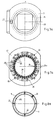
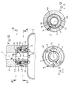
- the pivot bearing (6) of the implement carrier coupling according to FIGS. 1 to 9 is constructed in several parts and comprises an axle tube (15) inserted into the clutch housing (3) and axially rotatable therein, a flange sleeve (16) inserted into the clutch housing (16), which is supported with its flange (16a) as a circumferential radial surface (8) on the support ring (7) and comprises the axle tube (15) as a guide and rotatably supports it, a coupling ring (17) arranged concentrically around the axle tube (15), non-rotatably connected to the axle tube (15) and engaging in the clutch housing (3) and one which fits into the coupling ring (17) and is screwed onto the axle tube (15) and holds the coupling ring (17) between itself and the flange sleeve (16) in the bearing play and the rotational movement in the axial direction and in its set position with the coupling ring (17 ) Lockable adjusting ring (11), the threaded connection between the axle tube (15) and adjusting
- the axle tube (15) shows a gradation (15a, 15b) in the outer diameter which is reduced at the upper and lower tube ends; a cylindrical bearing ring (19) is arranged around the upper step (15a) and the flange sleeve (16) is arranged around the lower step (15b) and the end of the lower step (15b) protruding downward from the flange sleeve (16b) has an external thread (13a) for the adjusting ring (11).
- the support ring (7) is formed by a retaining ring, preferably a circlip, inserted into an annular groove (20) of the clutch housing (3).
- the adjusting ring (11) is designed as an axle nut with an internal thread (13b), several axial insertion holes (22) for a tool for rotating the ring and an axial threaded bore (23) for a locking screw (24) which interacts with the coupling ring (17), the screw (24) sunk into the countersunk threaded hole (23).
- the coupling ring (17) shows, on a circular ring running at a distance around the axle tube (15), a plurality of blind holes (25) made axially from its underside, into which, depending on the screwed position of the adjusting ring (11), its locking screw (24) for securing the setting of the clutch ring (17).
- the coupling ring (17) on a circular ring that runs around the blind holes (25) at a distance in its ring edge (17a), which is adjacent to the coupling housing (3) and is stepped with respect to its upper ring surface (21), has a maximum angle of rotation of 350 degrees and with Grooves (26) forming stops (26a) forming two ends adjacent to each other and into which a lug (27) of the coupling housing (3) surrounds the rotation limitation occurring in both directions of rotation of the rotary bearing (6).
- the coupling ring (17) has a plurality of fastening holes (30) accessible from the underside of the ring, preferably nuts (30) let into the coupling ring (17), for fastening the control housing (2) or the control panel (2) by means of screws ( 32).
- a gasket (31) in flat plate form is arranged between the underside of the coupling ring (17) and the control housing (2) or the control panel (2).
- An axial slot (33) is recessed in the lower end region in the axle tube (15), into which the coupling ring (17) engages with a nose (34) protruding on the inside and connects the two parts (17, 15) rotatably to one another.
- the cylindrical bearing ring (19) is first pressed into the bore (35) of the clutch housing (3) from below to in front of the stop (35a) and then the axle tube (15) is inserted from below, which is then with its upper one Gradation (15a) surrounds in the bearing ring (19). Then the cylindrical flange sleeve (16) is pushed from below onto the axle tube (15), namely its lower step (15b), and pressed into the housing (3) - its bore (35) - the vertical, cylindrical sleeve part (16b) between the housing bore (35) and the axle tube (15) lies and the flange (16a) engages in an annular recess (36) of the housing (3).
- the support ring (7) is inserted from below into the annular groove (20) of the housing (3) and is located below the radial surface (8) of the sleeve flange (16a), whereby the flange sleeve (16) is carried and the axle tube (15) is supported with the gradation base (15c) hanging on the cylindrical sleeve part (16b).
- the coupling ring (17) is inserted into the coupling housing (3) from below with the interposition of an annular seal (39) and encompasses the lower gradation area (15b) of the axle tube (15).
- the adjusting ring (11) is then screwed onto the axle tube (15) from below, engages in a recess (38) of the coupling ring (17) and acts with its clamping surface (9) against the radial surface (38a) of the recess (38 ) and thus carries the coupling ring (17).
- the internal thread (13b) of the adjusting ring (11) and the external thread (13a) of the axle tube (15) form the axial clamping device (13).
- the locking screw (24) is then screwed into the adjusting ring (11), which then engages in one of the holes (25) in the coupling ring (17) and thereby secures the setting made.
- control housing (2) or the control panel (2) is fastened under the rotary bearing (6) by means of the screws (32) engaging in the threaded holes (30) with the flange seal (31) being interposed.
- axle tube (15) with the coupling ring (17) and adjusting ring (11) as well as the control housing (2) or the control panel (2) can then be rotated axially with respect to the clutch housing (3), the axle tube (15) in the fixed bearing ring ( 19) and is rotatably guided in the fixed flange sleeve (16).
- the support tube (1) preferably has a circular cross-section and engages in a square tube receptacle (39) of the coupling housing (3) from above, and a hand lever (54) with screw (55) and wedge (56) is additionally mounted in the housing (3) , wherein the wedge (56) against the support tube (1) for additional locking in the housing (3) can be tensioned (Fig. 2).
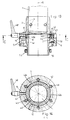
- the rotary bearing (6) according to the second embodiment of the implement carrier coupling according to FIGS. 10 to 12 is of a tubular connecting piece (41) which is rotatably suspended in the coupling housing (3) with its upper end designed as a truncated cone (40) on the supporting ring (7).
- a slotted, conical adjusting ring (12) which is used to adjust the bearing play and the rotation of the connector (41) by a radial clamping member (14) against the connector truncated cone (40) is exciting.
- the truncated cone (40) protrudes beyond the outer cross section of the connecting piece (41), tapers upwards and towards the axis of rotation (5), becomes circumferential on its shell side Tapered surface (40a) from the adjusting ring (12) under pressure and forms with its lower, horizontal, truncated cone surface projecting radially beyond the connecting piece (41) a circumferential radial surface (8) for resting on the support ring (7).
- the adjusting ring (12) has a triangular or trapezoidal cross-section with the conical surface as the clamping surface (10) on the truncated cone (40) and is preferably made of plastic.
- the adjusting ring (12) and the connecting piece truncated cone (40) lie in a cylindrical bag receptacle (42) of the coupling housing (3) and this bag receptacle (42) preferably shows a plurality of circumferentially distributed devices which rest against the adjusting ring (12). inwardly protruding surface areas (jetties) (42a) for a multi-zone (multi-point) system.
- the support ring (7) is preferably divided into two (FIG. 11) and is held in the sack receptacle (42) in the clutch housing (3) by a plurality of screws (43) running parallel to the axis of rotation of the support tube (5);
- a slide ring (44) made of plastic or the like can be arranged between the support ring (7) and the horizontal radial surface (8).
- the adjusting ring (12) engages over a preferably integrally formed anti-rotation lug (46) on the inside of the coupling housing (3), by means of which it is fixed against axial rotation (FIG. 12).
- the tensioning element (14) is formed by a screw which can be rotated radially in the coupling housing (3) in a threaded bore (47) and acts on the adjusting ring (12) outside the slot (45) and which acts as a Stud screw (Fig. 12) executed or provided with a handle (48), such as a rotary lever (Fig. 13 and 14).
- connection piece (41) is formed on its pipe end lying outside (below) the coupling housing (3) to form a fastening flange (49), under which the control housing (2) or the control panel (2) is fastened by means of screws (32). is attached (Fig. 10).
- the connecting piece (41) is guided downward as a receiving tube (50) from the coupling housing (3) and between an adjustable angle of rotation limit stop (51) arranged thereon and a lock nut ( 52) the control housing (2) or the control panel (2) detachably fixed (Fig. 13).
- the support ring (7) can also be designed as a one-piece ring as well as the slide ring (44).
- the receptacle (plug-screw connection) (4) in the coupling housing (3) is cylindrical with a circular cross-section and takes in a support tube (FIG. 14) that is circular or angular in cross-section, rounded on the corner and then secured in the vertical and rotational directions.
- a cover and protective tube (53) surrounding the limit stop (51) can be arranged on the clutch housing (3).
Landscapes
- Engineering & Computer Science (AREA)
- General Engineering & Computer Science (AREA)
- Mechanical Engineering (AREA)
- Pivots And Pivotal Connections (AREA)
- Joints Allowing Movement (AREA)
Applications Claiming Priority (2)
| Application Number | Priority Date | Filing Date | Title |
|---|---|---|---|
| DE4100625A DE4100625C1 (OSRAM) | 1991-01-11 | 1991-01-11 | |
| DE4100625 | 1991-01-11 |
Publications (2)
| Publication Number | Publication Date |
|---|---|
| EP0496191A1 EP0496191A1 (de) | 1992-07-29 |
| EP0496191B1 true EP0496191B1 (de) | 1995-04-05 |
Family
ID=6422835
Family Applications (1)
| Application Number | Title | Priority Date | Filing Date |
|---|---|---|---|
| EP92100039A Expired - Lifetime EP0496191B1 (de) | 1991-01-11 | 1992-01-03 | Geräteträgerkupplung für ein an einem Tragrohr drehbar aufgehängtes Steuergehäuse od. dgl. |
Country Status (3)
| Country | Link |
|---|---|
| EP (1) | EP0496191B1 (OSRAM) |
| AT (1) | ATE120835T1 (OSRAM) |
| DE (2) | DE4100625C1 (OSRAM) |
Cited By (1)
| Publication number | Priority date | Publication date | Assignee | Title |
|---|---|---|---|---|
| DE102016108802B3 (de) * | 2016-05-12 | 2017-04-06 | Tragfreund Gmbh | Tragvorrichtung |
Families Citing this family (4)
| Publication number | Priority date | Publication date | Assignee | Title |
|---|---|---|---|---|
| DE4238112A1 (de) * | 1992-11-12 | 1994-05-19 | Privates Inst Fuer Luft Und Ka | Sensorkühlfläche für Kaltfinger von Gaskältemaschinen |
| AT513065B1 (de) * | 2012-07-10 | 2014-03-15 | Bernecker & Rainer Ind Elektronik Gmbh | Tragarmanschluss |
| EP3009728B1 (de) * | 2014-10-17 | 2019-04-24 | Ondal Medical Systems GmbH | Sicherungselement für Stativvorrichtung sowie dazu korrespondierend ausgebildete Komponenten |
| AT517981B1 (de) * | 2015-11-23 | 2017-12-15 | B & R Ind Automation Gmbh | Dreh- und Schwenkgelenk mit einer Drehachse und einer Schwenkachse |
Family Cites Families (4)
| Publication number | Priority date | Publication date | Assignee | Title |
|---|---|---|---|---|
| CH484375A (fr) * | 1969-05-30 | 1970-01-15 | Neukomm Walter | Palier lisse à jeux axial et radial conjointement réglables |
| SE410214B (sv) * | 1978-04-11 | 1979-10-01 | Bergs Smide Ab K A | Kullagerlekare |
| GB2132297B (en) * | 1982-12-16 | 1986-07-23 | Goodrich Co B F | Pipe swivel joint |
| DE8804644U1 (de) * | 1988-04-08 | 1988-06-09 | Rose-Elektrotechnik Gmbh & Co Kg Elektrotechnische Fabrik, 32457 Porta Westfalica | Geräteträgerkupplung für ein an einem Tragrohr drehbar aufgehängtes Steuergehäuse |
-
1991
- 1991-01-11 DE DE4100625A patent/DE4100625C1/de not_active Expired - Lifetime
-
1992
- 1992-01-03 EP EP92100039A patent/EP0496191B1/de not_active Expired - Lifetime
- 1992-01-03 AT AT92100039T patent/ATE120835T1/de not_active IP Right Cessation
- 1992-01-03 DE DE59201795T patent/DE59201795D1/de not_active Expired - Lifetime
Cited By (2)
| Publication number | Priority date | Publication date | Assignee | Title |
|---|---|---|---|---|
| DE102016108802B3 (de) * | 2016-05-12 | 2017-04-06 | Tragfreund Gmbh | Tragvorrichtung |
| EP3244122A1 (de) | 2016-05-12 | 2017-11-15 | Tragfreund GmbH | Tragvorrichtung |
Also Published As
| Publication number | Publication date |
|---|---|
| ATE120835T1 (de) | 1995-04-15 |
| DE4100625C1 (OSRAM) | 1992-08-13 |
| DE59201795D1 (de) | 1995-05-11 |
| EP0496191A1 (de) | 1992-07-29 |
Similar Documents
| Publication | Publication Date | Title |
|---|---|---|
| DE102007037242B4 (de) | Befestigungseinrichtung mit Toleranzausgleich | |
| DE3420528A1 (de) | Stufenlos verstellbare hubvorrichtung | |
| DE69003574T2 (de) | Höheneinstellvorrichtung, insbesondere für Möbel. | |
| EP0647496A2 (de) | Bolzen | |
| DE69403278T2 (de) | Einstellbare Kupplung für Lackrührer | |
| DE3031216A1 (de) | Spannfutter fuer gewindebohrer. | |
| DE2617313C3 (de) | Teleskopisch verstellbare Stützvorrichtung | |
| EP0496191B1 (de) | Geräteträgerkupplung für ein an einem Tragrohr drehbar aufgehängtes Steuergehäuse od. dgl. | |
| DE10114854C1 (de) | Sanitäre Auslaufarmatur | |
| DE3440793A1 (de) | Polstermoebel | |
| EP1887166A2 (de) | Bodenbefestigungsvorrichtung für Rohre | |
| DE3618528A1 (de) | Messfuehler mit seitlichem haltearm | |
| DE2852520A1 (de) | Schwingungsdaempfer fuer rotierende bohrrohre an tiefbohrmaschinen | |
| EP0856275A1 (de) | Befestigungsanordnung für einen Toilettensitz | |
| DE7026952U (de) | Wandstuetze. | |
| DE29704779U1 (de) | Bohrkonsole zur Wandbefestigung von Heizkörpern | |
| DE4321708A1 (de) | Heizkörperkonsole | |
| DE3503022C2 (OSRAM) | ||
| EP0828949B1 (de) | Möbelstütze | |
| DE1602861C2 (de) | Mehrspindelbohrmaschine | |
| DE9013917U1 (de) | Vorrichtung zum Befestigen eines Klosett-Sitzes | |
| DE29819933U1 (de) | Rohrverbindung mit Überwurfmutter | |
| DE3239104A1 (de) | Verstellbare stuetze fuer trennwaende, handlaeufe od. dgl. | |
| WO1986005561A1 (fr) | Dispositif de fixation de vis | |
| DE4428286C2 (de) | Stanzstempeleinheit |
Legal Events
| Date | Code | Title | Description |
|---|---|---|---|
| PUAI | Public reference made under article 153(3) epc to a published international application that has entered the european phase |
Free format text: ORIGINAL CODE: 0009012 |
|
| AK | Designated contracting states |
Kind code of ref document: A1 Designated state(s): AT BE CH DE DK ES FR GB GR IT LI LU NL PT SE |
|
| 17P | Request for examination filed |
Effective date: 19921015 |
|
| 17Q | First examination report despatched |
Effective date: 19940329 |
|
| GRAA | (expected) grant |
Free format text: ORIGINAL CODE: 0009210 |
|
| AK | Designated contracting states |
Kind code of ref document: B1 Designated state(s): AT BE CH DE DK ES FR GB GR IT LI LU NL PT SE |
|
| PG25 | Lapsed in a contracting state [announced via postgrant information from national office to epo] |
Ref country code: ES Free format text: THE PATENT HAS BEEN ANNULLED BY A DECISION OF A NATIONAL AUTHORITY Effective date: 19950405 Ref country code: GR Free format text: LAPSE BECAUSE OF FAILURE TO SUBMIT A TRANSLATION OF THE DESCRIPTION OR TO PAY THE FEE WITHIN THE PRESCRIBED TIME-LIMIT Effective date: 19950405 Ref country code: DK Effective date: 19950405 |
|
| REF | Corresponds to: |
Ref document number: 120835 Country of ref document: AT Date of ref document: 19950415 Kind code of ref document: T |
|
| ITF | It: translation for a ep patent filed | ||
| REF | Corresponds to: |
Ref document number: 59201795 Country of ref document: DE Date of ref document: 19950511 |
|
| ET | Fr: translation filed | ||
| GBT | Gb: translation of ep patent filed (gb section 77(6)(a)/1977) |
Effective date: 19950419 |
|
| PG25 | Lapsed in a contracting state [announced via postgrant information from national office to epo] |
Ref country code: PT Effective date: 19950705 |
|
| PLBE | No opposition filed within time limit |
Free format text: ORIGINAL CODE: 0009261 |
|
| STAA | Information on the status of an ep patent application or granted ep patent |
Free format text: STATUS: NO OPPOSITION FILED WITHIN TIME LIMIT |
|
| 26N | No opposition filed | ||
| PGFP | Annual fee paid to national office [announced via postgrant information from national office to epo] |
Ref country code: LU Payment date: 19961201 Year of fee payment: 6 |
|
| PGFP | Annual fee paid to national office [announced via postgrant information from national office to epo] |
Ref country code: FR Payment date: 19961218 Year of fee payment: 6 |
|
| PGFP | Annual fee paid to national office [announced via postgrant information from national office to epo] |
Ref country code: GB Payment date: 19961227 Year of fee payment: 6 |
|
| PGFP | Annual fee paid to national office [announced via postgrant information from national office to epo] |
Ref country code: NL Payment date: 19961230 Year of fee payment: 6 |
|
| PGFP | Annual fee paid to national office [announced via postgrant information from national office to epo] |
Ref country code: BE Payment date: 19961231 Year of fee payment: 6 |
|
| PGFP | Annual fee paid to national office [announced via postgrant information from national office to epo] |
Ref country code: SE Payment date: 19970108 Year of fee payment: 6 |
|
| PG25 | Lapsed in a contracting state [announced via postgrant information from national office to epo] |
Ref country code: LU Free format text: LAPSE BECAUSE OF NON-PAYMENT OF DUE FEES Effective date: 19980103 Ref country code: GB Free format text: LAPSE BECAUSE OF NON-PAYMENT OF DUE FEES Effective date: 19980103 |
|
| PG25 | Lapsed in a contracting state [announced via postgrant information from national office to epo] |
Ref country code: SE Free format text: LAPSE BECAUSE OF NON-PAYMENT OF DUE FEES Effective date: 19980104 |
|
| PG25 | Lapsed in a contracting state [announced via postgrant information from national office to epo] |
Ref country code: BE Free format text: LAPSE BECAUSE OF NON-PAYMENT OF DUE FEES Effective date: 19980131 Ref country code: FR Free format text: THE PATENT HAS BEEN ANNULLED BY A DECISION OF A NATIONAL AUTHORITY Effective date: 19980131 |
|
| BERE | Be: lapsed |
Owner name: ROSE-ELEKTROTECHNIK G.M.B.H. + CO. K.G. ELEKTROTE Effective date: 19980131 |
|
| PG25 | Lapsed in a contracting state [announced via postgrant information from national office to epo] |
Ref country code: NL Free format text: LAPSE BECAUSE OF NON-PAYMENT OF DUE FEES Effective date: 19980801 |
|
| GBPC | Gb: european patent ceased through non-payment of renewal fee |
Effective date: 19980103 |
|
| NLV4 | Nl: lapsed or anulled due to non-payment of the annual fee |
Effective date: 19980801 |
|
| EUG | Se: european patent has lapsed |
Ref document number: 92100039.4 |
|
| REG | Reference to a national code |
Ref country code: FR Ref legal event code: ST |
|
| PGFP | Annual fee paid to national office [announced via postgrant information from national office to epo] |
Ref country code: DE Payment date: 20110201 Year of fee payment: 20 Ref country code: CH Payment date: 20110112 Year of fee payment: 20 Ref country code: IT Payment date: 20110114 Year of fee payment: 20 Ref country code: AT Payment date: 20101222 Year of fee payment: 20 |
|
| REG | Reference to a national code |
Ref country code: DE Ref legal event code: R071 Ref document number: 59201795 Country of ref document: DE |
|
| REG | Reference to a national code |
Ref country code: DE Ref legal event code: R071 Ref document number: 59201795 Country of ref document: DE |
|
| REG | Reference to a national code |
Ref country code: CH Ref legal event code: PL |
|
| REG | Reference to a national code |
Ref country code: AT Ref legal event code: MK07 Ref document number: 120835 Country of ref document: AT Kind code of ref document: T Effective date: 20120103 |
|
| PG25 | Lapsed in a contracting state [announced via postgrant information from national office to epo] |
Ref country code: DE Free format text: LAPSE BECAUSE OF EXPIRATION OF PROTECTION Effective date: 20120104 |