EP0495818B1 - Coin storage device - Google Patents
Coin storage device Download PDFInfo
- Publication number
- EP0495818B1 EP0495818B1 EP90914750A EP90914750A EP0495818B1 EP 0495818 B1 EP0495818 B1 EP 0495818B1 EP 90914750 A EP90914750 A EP 90914750A EP 90914750 A EP90914750 A EP 90914750A EP 0495818 B1 EP0495818 B1 EP 0495818B1
- Authority
- EP
- European Patent Office
- Prior art keywords
- coins
- coin
- store
- stores
- exit
- Prior art date
- Legal status (The legal status is an assumption and is not a legal conclusion. Google has not performed a legal analysis and makes no representation as to the accuracy of the status listed.)
- Expired - Lifetime
Links
- 238000000034 method Methods 0.000 claims description 10
- 230000014759 maintenance of location Effects 0.000 claims description 9
- 230000004044 response Effects 0.000 claims description 3
- 230000001419 dependent effect Effects 0.000 claims description 2
- 230000002401 inhibitory effect Effects 0.000 claims 1
- 230000000717 retained effect Effects 0.000 description 8
- 230000008859 change Effects 0.000 description 6
- 230000008901 benefit Effects 0.000 description 4
- 241000237858 Gastropoda Species 0.000 description 1
- 238000010276 construction Methods 0.000 description 1
- 238000000151 deposition Methods 0.000 description 1
- 238000006073 displacement reaction Methods 0.000 description 1
- 230000005484 gravity Effects 0.000 description 1
- 238000003780 insertion Methods 0.000 description 1
- 230000037431 insertion Effects 0.000 description 1
- 238000009434 installation Methods 0.000 description 1
- 230000007246 mechanism Effects 0.000 description 1
- 229920003023 plastic Polymers 0.000 description 1
- 239000004033 plastic Substances 0.000 description 1
- 230000008569 process Effects 0.000 description 1
- 230000000750 progressive effect Effects 0.000 description 1
- 230000001960 triggered effect Effects 0.000 description 1
Images


Classifications
-
- G—PHYSICS
- G07—CHECKING-DEVICES
- G07F—COIN-FREED OR LIKE APPARATUS
- G07F1/00—Coin inlet arrangements; Coins specially adapted to operate coin-freed mechanisms
- G07F1/04—Coin chutes
- G07F1/047—Coin chutes with means for temporarily storing coins
-
- G—PHYSICS
- G07—CHECKING-DEVICES
- G07F—COIN-FREED OR LIKE APPARATUS
- G07F1/00—Coin inlet arrangements; Coins specially adapted to operate coin-freed mechanisms
- G07F1/04—Coin chutes
-
- G—PHYSICS
- G07—CHECKING-DEVICES
- G07F—COIN-FREED OR LIKE APPARATUS
- G07F5/00—Coin-actuated mechanisms; Interlocks
- G07F5/24—Coin-actuated mechanisms; Interlocks with change-giving
-
- G—PHYSICS
- G07—CHECKING-DEVICES
- G07F—COIN-FREED OR LIKE APPARATUS
- G07F9/00—Details other than those peculiar to special kinds or types of apparatus
- G07F9/04—Means for returning surplus or unused coins
Definitions
- This invention relates to coin stores, and is particularly but not exclusively concerned with coin escrows, which are stores used, e.g. in payphones, for temporarily retaining coins before dispensing them so that they can either be retained in a cash box or refunded to a user.
- a more compact storage arrangement is shown in GB-A-2135094, in which coins can be stored in successive turns of a spring. Coins are dispensed to a cash box by turning the spring so that the coins move stepwise to a sorter where the coins are allowed to leave the spring at different positions, depending on their diameter. At the other end of the spring is an exit path from which coins can be delivered to a return channel.
- this arrangement allows little control over the sequence in which coins are sent to the cash box, this sequence being dependent mainly on the order in which the coins are received by the spring and the respective coin diameters.
- a coin store in which a group of coins of different denominations can be reciprocated with respect to first and second exit points at each of which a coin of any of said denominations can be taken away from the group and delivered to a cash retention means, whereby the sequence in which coins are delivered to the cash retention means can be controlled by selectively moving the coin group in one direction to dispense a coin from the first exit point, and the opposite direction to dispense a coin from the second exit point.
- the exit point from which to take a coin the order in which the coins are dispensed can be controlled so that the dispensing sequence differs from the entry sequence.
- the dispensed coins from both exits are preferably routed to a coin retention means, e.g. one or more cash boxes.
- a coin retention means e.g. one or more cash boxes.
- the coins are stored face-to-face for compactness, and preferably individually to facilitate the addition or removal of a coin from the group.
- a coin store of the invention comprises a helical structure for receiving coins of a plurality of denominations and storing them between successive helical turns so that they can be moved, by rotation of the structure, relative to two exit points at which a coin of any of said denominations can be added to or taken away from the store.
- exits are located at opposite ends of a region in which the coins are stored, and wherein there is a coin entry point located at or near one of these ends.
- the store has a third exit leading to a refund path.
- the store has a control means which selects coins for dispensing from the store according to the values of the coins.
- the control means may also take into account the positions of the coins within the store, particularly if only certain coins are available for dispensing in dependence upon their position.
- the invention also extends to a coin handling apparatus including a coin validator and a coin store according to the invention positioned to receive coins from the validator.
- the system has two or more such stores, and the validator may be arranged to deliver coins selectively to either store. This enables a greater volume of coins to be stored, and a greater degree of choice in the selective dispensing of the coins.
- the system is preferably arranged to control the store to which coins are directed in dependence upon the value of the coins as detected by the coin validator; if for example high denomination coins are directed to one store and low denomination coins to the other store, this will improve the likelihood that a coin of approximately the right denomination will be available for dispensing.
- the system is preferably arranged to detect a fault in either one of the stores, and in response thereto to disable that store, so that the system may continue functioning correctly using only one of the stores.
- a method of controlling a coin handling system having a coin validator for use with coins of a plurality of denominations and two or more coin stores each of which is capable of receiving and storing coins of any of said denominations from the validator, the method comprising selecting the store to which coins are to be delivered in dependence upon the values of the coins, such that a first of the stores retains predominantly low-denomination coins and a second of the stores retains predominantly high-denomination coins and selectively dispensing coins from each of the coin stores.
- a coin validator 2 of known form preferably using electronic circuitry for validating coins while they are travelling down a coin path, has at its exit an accept gate mechanism 4. If the coins are deemed acceptable, they are delivered to an accept path 6. Otherwise, they are delivered to a reject path 8, which returns the coins to the user.
- the accept path 6 leads to a sorter 10 which selectively directs the coins to a first routing path 12 or a second routing path 14 leading, respectively, to coin stores 16 and 18.
- Each of the coin stores has a refund path 20 and 22, respectively, which direct coins dispensed by the coin stores to the reject path 8, and thus back to the user.
- Each store also has two cash box paths, the paths for store 16 being indicated at 24 and 26, and those for store 18 at 28 and 30, all of which lead to a coin retention means in the form of a common cash box 32. Separate cash boxes could be used instead, if desired.
- a control means 34 responds to signals from the validator 2 by controlling the accept gate 4 to cause genuine coins of known denomination to travel along accept path 6 to the sorter 10.
- the control means determines whether the coin should then be directed along path 12 or path 14 in dependence upon the denomination of the coin as detected by the validator 2. Low denomination coins are delivered to the store 16, and high denomination coins to the store 18. If either store is full, the control means 34 is arranged to cause further coins to be directed to the other store, irrespective of denomination.
- the control means 34 is able to send a signal to the validator 2 to cause it to reject all coins, and therefore deliver them to the refund path 8, if both the stores 16 and 18 are full.
- the control means 34 has a memory which stores information indicating what coins are presently in the stores 16 and 18, and their positions within the stores. This information also indicates which of these coins are presently positioned so that they are available for dispensing along one of the cash box paths 24 to 30.
- the system is particularly suited for installation in a machine, such as a payphone, where the cost of any transaction is not determinable at the beginning of the transaction, and possibly where it increases in a progressive manner during the course of the transaction.
- the control means 34 causes the stores 16 and 18 to deliver to the cash box 32 coins which have a total value equal to or greater than the value of the transaction, and delivers the remaining coins as change along the refund paths 20 and 22.
- the control means 34 is arranged to select the coins which are retained and dispensed in such a manner that the change given to the user is greater than that which would be available if the coins were simply retained in the order in which they were inserted, and is preferably maximised having regard to the constraints of the system.
- coins are delivered to the cash box 32 one-by-one during the course of the transaction.
- One way in which this may be achieved would be for the control means to receive a signal on line 36 from the host machine, e.g. the controller of the payphone, indicating the expenditure of credit.
- the control means 34 would cause the highest-value coin presently available for dispensing (and probably stored in store 18) to be dispensed to the cash box 32.
- the amount of the expended credit would be reduced accordingly, and the operation would continue, so that the next coin would be dispensed when the current expenditure again increased to the amount corresponding to the highest-value coin in the stores 16 and 18.
- this routine can be varied in a number of ways. For example, dispensing may be triggered at the point at which the expended credit is equal to the value of the highest-value coin actually available for dispensing.
- the control means is arranged to control the stores 16 and 18 so that the spaces becoming vacant as a result of the dispensing of coins can be filled by newly-inserted coins.
- the control means causes the delivery to the cash box 32 of coins equal to or exceeding in value the current amount of expended credit.
- the selection of the coins to be dispensed from the stores 16 and 18 is controlled so that the amount by which the value of the coins directed to the cash box 32 exceeds the current expended credit is minimised. For this purpose, it is desirable to have available low-value coins, which would normally be in the store 16.
- the construction of the store 16 will be described in more detail with reference to Figures 2 to 6.
- the store 18 is of identical structure.
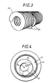
- the store 16 comprises a helical member 40, also referred to herein as a helix, having a horizontal axis. This is located within an inner tube 42, which is itself located within an outer tube 44, both tubes also having horizontal axes.
- a motor (not shown) is provided to rotate the helix, which will cause translatory movement of the coin in the direction of the axis of the helix.
- the coins can be moved successively along the helix to make room for more coins received via the entry.
- Figure 3 shows two coins 46 positioned within successive turns of the helix.
- the coins are in a face-to-face orientation, thus enabling a fairly compact structure, (b) that the coins may be of different denomination and substantially different sizes, but nevertheless be positioned reliably, and (c) that the coins are retained in individual sections, rather than engaging each other, which will facilitate the individual dispensing of the coins to be described later.
- the tubes 42 and 44 have apertures at selected positions, and these selectively provide access to particular regions of the helix 40.
- pairs of apertures can be brought into registry with selected locations in the helix so as to provide access points for permitting coins to enter or exit the store.
- each location being disposed between successive turns of the helix.
- These are represented schematically in Figure 7.
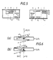
- the apertures in the tubes 42 and 44 are so located as to provide an entry access point at location 7, and exit access points at locations 1, 6 and 8. This is achieved by grouping the apertures into three circumferential sections in each of the tubes 42 and 44, in the-manner illustrated in Figure 5 which shows schematically the positions of the apertures as represented on flattened-out versions of the tubes.
- sections A are both positioned directly beneath the helical member 40.
- section A of inner tube 42 has no apertures, this provides a smooth surface permitting the coins to ride along the surface as the helix rotates and the coins move.
- apertures I5 and O4 are aligned beneath location 1, providing an access point to cash box path 26.
- both the entrance and the exit paths are substantially vertical at the access points to the helical member. Because the tubes 42 and 44 have an odd number of sections, the tube positions which are appropriate to locate the sections directly underneath the helical member will be inappropriate for locating those sections directly above the member. In order to provide an access point for entry of the coins to location 7, section B of inner tube 42 and section C of outer tube 44 have to be located directly above the helical member, so that apertures I2 and O6 are in registry with location 7. In addition therefore to the three tube positions required to provide the exit paths, there is also an intermediate position for each tube to provide an access point at the entry location.
- each tube is movable in steps of 60° about its axis. This permits each tube to be located at the desired positions to allow indexing of the coins within the tubes or exit of selected coins, and in addition permits each tube to be positioned in the intermediate location required for entry of a coin.
- FIG. 4 it will be noted that the axis 50 of the helical member 40 is displaced from the axis 52 of the two co-axial tubes 42 and 44.
- the axis 50 is displaced vertically so as to ensure support even for the smaller coins which rest upon the inner surface of the tube 42.
- the horizontal displacement will be explained with reference to Figure 6.
- Figure 6(a) shows in plan view the position of the part 58 of the helical member 40 located under the apertures I2, O6 providing access at the coin entry, assuming that the axis 50 of the helical member 40 were to be located in the same vertical plane as the axis 52 of the tubes 42 and 44.
- An incoming coin will enter vertically downwardly as indicated at 54.
- the lowermost part of this part 58 of the helical member 40 will be located directly beneath the coin entry path, and therefore the coin could come to rest at either side of the part 58. This means that the location of the coin will be to some extent indeterminate.
- the locations within the helical member 40 as shown in Figure 7 are evenly spaced at the pitch of the helix.
- the motor driving the helical member is arranged to rotate it by 360° in order to index the coins along the member, i.e. to move them stepwise by one location.
- the helical member is positioned with the part which is in the centre of each location at the uppermost point.
- the part 58 which is in the centre of the location must be at the lowermost point.
- the motor in addition to rotating the helical member by 360°, the motor must also be capable of rotating it by 180° in order to prepare the member for reception of a coin via the entry access point. After entry of the coin, the motor is rotated in the reverse direction by 180°.
- the motors driving the helical member 40 and the tubes 42 and 44 may be stepper motors. Alternatively, or additionally, sensors may be provided for indicating whether or not the driven member or tube has reached any of its desired locations.
- the tubes 42 and 44 may form extensions of the armatures of their respective motors.
- Means are provided for sensing a fault condition in either of the stores 16 and 18.
- Such means can take the form of a jam detector specifically designed for this purpose.
- the position sensors used to detect the location of the helical member and thus control its rotation may also be used for this purpose.
- a fault could be indicated if the position sensor indicates that the selected position has not been adopted within a predetermined time of energising the motor.
- Fault conditions are signalled to the control means 34. Once a fault condition is detected in one of the stores, further coins are routed only to the other store. The control means will issue the signal causing the validator to reject all coins whenever the remaining store is full.
- the design of the stores including the helix, is inherently reliable. Because each coin is individually and positively driven when it is moved, jamming due to faceted, wet or dirty coins is less likely to occur. Also, it is possible to attempt to clear suspected jam conditions by reversing the direction of rotation of the helix, rotating the inner tube, etc. If desired, the machine can be arranged automatically to operate the store, e.g. by rotating the helix when no coin is present in the system, to flush out any debris that may have accumulated, which would then be delivered to the refund path.
- Figure 8 illustrates one example of a way in which the control means 34 may operate the store 16 during the course of a transaction.
- Figure 8(I) shows the state of the store after the first coin A has been received. Immediately after reception, the helical member is rotated to shift the coin to location 6 to leave location 7 free for the next coin, as shown in Figure 8(II).
- control means assumes that only the endmost coins, in this case A and F, are available for dispensing to the cash box during the course of a transaction.
- the paths to the cash box are at locations 1 and 6, so that the endmost coins can always be dispensed from one or other of these locations, if necessary by shifting the coins along so that the left-most coin reaches location 1.
- control means 34 When the control means 34 detects that a coin is to be dispensed, it checks which of the available coins in both stores has the highest-value. Assuming that this is coin F, then the coin is dispensed so that the store adopts the state shown in Figure 8(IV). The coins are then indexed to the position shown in Figure 8(V), so that there will be no gaps between these and any further coin which may be inserted.
- control means 34 determines which of the coins presently contained in the store should be retained, and which refunded, in order to ensure that sufficient value is given by the user, but that the value of his change is maximised. There are no restrictions on which of the coins can be refunded and which retained, as explained below.
- the coins are kept together in a group which is maintained within a region having cash box exits at each end thereof.
- the refund exit is located outside this region. This means that at least the endmost coins in the group can be dispensed to the cash box during the course of the transaction.
- the coins can all be stepped past one of the cash box exits to reach the refund exit. Accordingly, any one of the coins can be directed to the cash box, or can stay in the store until it reaches the refund exit, where it is refunded.
- This arrangement therefore provides a very flexible technique for controlling the destinations of the coins.
- the store (16 or 18) comprises a hollow plastics cylinder 80 having on its inner surface an integrally-formed helical structure 82 extending radially inwardly therefrom.
- a gear extending around the outer circumference, as schematically illustrated at 84. This meshes with a further gear 86 which is indirectly driven by a stepper motor (not shown). Accordingly, rotation of the stepper motor causes rotation of the cylinder 80 about its axis 88.
- the helical structure 82 defines nine compartments as schematically illustrated in Figure 10, each compartment comprising the space between successive turns of the helical structure.
- the left-most compartment has a permanently open slot 90 by means of which coins can pass from the store to the cash box path 26.
- the next six compartments, shown as 1 to 6 in Figure 10, define the region in which the coins are normally stored during use of the device.
- the next compartment has an opening 92 leading to the cash box path 24 and, at the opposite side of the cylinder, an opening 94 leading to the coin entry path 12.
- the right-most compartment has an opening 96 leading to the refund path 20.
- the gate 98 closes the cash box path 24 so that any incoming coin from the path 12 will rest on the gate. This is then moved to the left (in the orientation of the drawings) to allow room for further coins to enter.
- the compartments 1 to 6 can be gradually filled in this way.
- the structure can be rotated to cause the coin at the left-most end of the stored group to be dispensed to cash box path 26.
- the gate 98 can be shifted away from the cash box 24, and the helical structure rotated in the opposite direction to dispense the right-most coin into cash box path 24.
- the helical structure is turned so that the group of coins moves successively toward the right, and the gate 98 is controlled in dependence upon whether the coins are to be dispensed into path 24 or path 20.
- control means 34 was required to memorise the denominations and locations of each of the coins in the stores.
- a store may have different areas designated for different denominations of coin, so that memorisation of the individual positions of inserted coins is no longer needed, so long as the positioning of the newly-inserted coins is controlled appropriately.
- the helical member has the advantage that the coins within the store can be shifted without requiring translatory motion of the storage structure, i.e. simply by rotating it, so that the store may be housed in a small space.
- An alternative arrangement which avoids bodily translational movement of the support structure would be an endless conveyor belt having means defining compartments for receiving the coins.
- coin is intended herein to mean genuine coins, tokens, counterfeit coins, slugs, washers and any other such item.
Landscapes
- Physics & Mathematics (AREA)
- General Physics & Mathematics (AREA)
- Control Of Vending Devices And Auxiliary Devices For Vending Devices (AREA)
- Vending Machines For Individual Products (AREA)
- Basic Packing Technique (AREA)
- Purses, Travelling Bags, Baskets, Or Suitcases (AREA)
Applications Claiming Priority (3)
| Application Number | Priority Date | Filing Date | Title |
|---|---|---|---|
| GB8923006A GB2236887B (en) | 1989-10-12 | 1989-10-12 | Coin storage device |
| GB8923006 | 1989-10-12 | ||
| PCT/GB1990/001526 WO1991006073A1 (en) | 1989-10-12 | 1990-10-04 | Coin storage device |
Publications (2)
| Publication Number | Publication Date |
|---|---|
| EP0495818A1 EP0495818A1 (en) | 1992-07-29 |
| EP0495818B1 true EP0495818B1 (en) | 1994-12-28 |
Family
ID=10664466
Family Applications (1)
| Application Number | Title | Priority Date | Filing Date |
|---|---|---|---|
| EP90914750A Expired - Lifetime EP0495818B1 (en) | 1989-10-12 | 1990-10-04 | Coin storage device |
Country Status (14)
| Country | Link |
|---|---|
| US (1) | US5356333A (fa) |
| EP (1) | EP0495818B1 (fa) |
| JP (1) | JPH05501318A (fa) |
| KR (1) | KR960006844B1 (fa) |
| CN (1) | CN1051803A (fa) |
| AT (1) | ATE116458T1 (fa) |
| AU (1) | AU6517590A (fa) |
| CA (1) | CA2067190A1 (fa) |
| DE (1) | DE69015645T2 (fa) |
| ES (1) | ES2065550T3 (fa) |
| GB (1) | GB2236887B (fa) |
| IE (1) | IE903644A1 (fa) |
| TW (1) | TW222338B (fa) |
| WO (1) | WO1991006073A1 (fa) |
Families Citing this family (16)
| Publication number | Priority date | Publication date | Assignee | Title |
|---|---|---|---|---|
| GB2260212B (en) * | 1991-10-04 | 1995-02-15 | Mars Inc | Coin storage device |
| GB2264405B (en) * | 1992-02-12 | 1996-06-12 | Mars Inc | Stepper motor drive circuit |
| GB9602894D0 (en) * | 1996-02-13 | 1996-04-10 | Thorn Transit Systems Int | Apparatus for sorting and/or storing coins |
| EP0962898A2 (en) | 1996-10-23 | 1999-12-08 | Thorn Transit Systems International Limited | A coin handling system |
| GB2326504A (en) * | 1997-06-18 | 1998-12-23 | Mars Inc | Currency handling apparatus capable of predicting future cash demands |
| KR20010001070A (ko) * | 1999-06-01 | 2001-01-05 | 옥성일 | 필름 자막기용 동판의 인출장치 |
| ES2161649B2 (es) * | 2000-05-29 | 2004-03-16 | Siemens Sa | Almacen intermedio de monedas con movimiento translacional para telefonos publicos. |
| DE10343774A1 (de) * | 2003-09-18 | 2005-05-04 | Walter Hanke Mech Werkstaetten | Zwischenkasse für einen münzbetätigten Automaten |
| US8139054B2 (en) | 2005-12-30 | 2012-03-20 | Mediatek Inc. | Luminance compensation apparatus and method |
| ATE551682T1 (de) * | 2010-02-02 | 2012-04-15 | Scheidt & Bachmann Gmbh | Münzspeicher mit speicherkette |
| US8522950B2 (en) * | 2011-09-09 | 2013-09-03 | Outerwall Inc. | Debris diverter for coin counting machine and associated method of manufacture and operation |
| US9036890B2 (en) | 2012-06-05 | 2015-05-19 | Outerwall Inc. | Optical coin discrimination systems and methods for use with consumer-operated kiosks and the like |
| US8967361B2 (en) | 2013-02-27 | 2015-03-03 | Outerwall Inc. | Coin counting and sorting machines |
| US9022841B2 (en) | 2013-05-08 | 2015-05-05 | Outerwall Inc. | Coin counting and/or sorting machines and associated systems and methods |
| US9235945B2 (en) | 2014-02-10 | 2016-01-12 | Outerwall Inc. | Coin input apparatuses and associated methods and systems |
| GB201915439D0 (en) * | 2019-10-24 | 2019-12-11 | Crane Payment Innovations Ltd | Money item handling system and method |
Family Cites Families (21)
| Publication number | Priority date | Publication date | Assignee | Title |
|---|---|---|---|---|
| US1625979A (en) * | 1925-08-21 | 1927-04-26 | Frederic H Brinkerhoff | Coin magazine |
| GB442406A (en) * | 1935-05-31 | 1936-02-07 | Francis Jonneret | Improvements in and relating to coin-freed automatic distributing apparatus |
| GB992911A (en) * | 1963-11-22 | 1965-05-26 | Scheidt & Bachmann Gmbh | Improvements in or relating to coin acceptance controlling devices for automatic vending machines |
| DE1957092A1 (de) * | 1969-08-27 | 1971-03-04 | Nordhausen Veb Fernmeldewerk | Anordnung zum Pruefen und Kassieren von Muenzen,insbesondere in Muenzfernsprechern |
| DD95874A5 (fa) * | 1971-05-05 | 1973-02-20 | ||
| US3896915A (en) * | 1973-01-17 | 1975-07-29 | Nippon Coinco Co Ltd | Vending machine |
| US3948377A (en) * | 1973-01-17 | 1976-04-06 | Nippon Coinco Co., Ltd. | Coin handling apparatus for a vending machine |
| FR2293749A1 (fr) * | 1974-12-05 | 1976-07-02 | Crouzet Sa | Magasin de stockage avec trop plein pour pieces de monnaie |
| DE2726142C3 (de) * | 1977-06-10 | 1979-12-20 | Scheidt & Bachmann Gmbh, 4050 Moenchengladbach | Vorrichtung zum zeitweisen Speichern von Münzen unterschiedlicher Wertigkeit |
| US4167949A (en) * | 1977-08-12 | 1979-09-18 | Glory Kogyo Kabushiki Kaisha | Coin jamming detecting device in coin sorting machine |
| CH635950A5 (de) * | 1978-11-22 | 1983-04-29 | Sodeco Compteurs De Geneve | Muenzspeicher. |
| GB2070307A (en) * | 1980-02-18 | 1981-09-03 | Gen Electric Co Ltd | Coin handling |
| US4360034A (en) * | 1980-04-09 | 1982-11-23 | Joseph C. Gianotti, Trustee | Coin sorter-counter |
| GB2088108B (en) * | 1980-11-26 | 1984-09-12 | Plessey Co The Ltd | Coin operated equipment |
| GB2097165A (en) * | 1981-04-10 | 1982-10-27 | Gen Electric Plc | Coin handling mechanism |
| JPS599786A (ja) * | 1982-07-08 | 1984-01-19 | 株式会社湊製作所 | 硬貨自動入出金機 |
| DE3304336C2 (de) * | 1983-02-09 | 1985-01-17 | Scheidt & Bachmann GmbH, 4050 Mönchengladbach | Speichereinrichtung zur Annahme und Rückgabe von Münzen für münzbetätigte Geräte |
| DE3307438C2 (de) * | 1983-03-03 | 1985-02-07 | Scheidt & Bachmann GmbH, 4050 Mönchengladbach | Münzspeicher zur Speicherung und Rückgabe von Münzen gleicher Wertigkeit |
| DE3318124A1 (de) * | 1983-05-18 | 1984-11-22 | Heinrich H. Klüssendorf GmbH & Co KG, 1000 Berlin | Vorrichtung zum speichern flacher und vorzugsweise runder gegenstaende |
| FR2609341B1 (fr) * | 1987-01-06 | 1989-03-03 | Cga Hbs | Distributeur automatique a rendu de monnaie |
| ES2004536A6 (es) * | 1987-03-03 | 1989-01-16 | Azkoyen Ind Sa | Mecanismo para la recepcion y cobro de monedas en maquinas accionables por monedas |
-
1989
- 1989-10-12 GB GB8923006A patent/GB2236887B/en not_active Expired - Fee Related
-
1990
- 1990-10-04 KR KR1019920700837A patent/KR960006844B1/ko not_active Expired - Fee Related
- 1990-10-04 ES ES90914750T patent/ES2065550T3/es not_active Expired - Lifetime
- 1990-10-04 US US07/847,015 patent/US5356333A/en not_active Expired - Fee Related
- 1990-10-04 WO PCT/GB1990/001526 patent/WO1991006073A1/en not_active Ceased
- 1990-10-04 CA CA002067190A patent/CA2067190A1/en not_active Abandoned
- 1990-10-04 JP JP2513655A patent/JPH05501318A/ja active Pending
- 1990-10-04 AT AT90914750T patent/ATE116458T1/de not_active IP Right Cessation
- 1990-10-04 EP EP90914750A patent/EP0495818B1/en not_active Expired - Lifetime
- 1990-10-04 DE DE69015645T patent/DE69015645T2/de not_active Expired - Fee Related
- 1990-10-04 AU AU65175/90A patent/AU6517590A/en not_active Abandoned
- 1990-10-11 TW TW079108549A patent/TW222338B/zh active
- 1990-10-11 IE IE364490A patent/IE903644A1/en unknown
- 1990-10-12 CN CN90109364A patent/CN1051803A/zh active Pending
Also Published As
| Publication number | Publication date |
|---|---|
| KR960006844B1 (ko) | 1996-05-23 |
| GB2236887A (en) | 1991-04-17 |
| EP0495818A1 (en) | 1992-07-29 |
| KR920704245A (ko) | 1992-12-19 |
| GB2236887B (en) | 1994-02-09 |
| GB8923006D0 (en) | 1989-11-29 |
| DE69015645D1 (de) | 1995-02-09 |
| DE69015645T2 (de) | 1995-05-11 |
| TW222338B (fa) | 1994-04-11 |
| IE903644A1 (en) | 1991-04-24 |
| CN1051803A (zh) | 1991-05-29 |
| WO1991006073A1 (en) | 1991-05-02 |
| US5356333A (en) | 1994-10-18 |
| AU6517590A (en) | 1991-05-16 |
| JPH05501318A (ja) | 1993-03-11 |
| ES2065550T3 (es) | 1995-02-16 |
| CA2067190A1 (en) | 1991-04-13 |
| ATE116458T1 (de) | 1995-01-15 |
Similar Documents
| Publication | Publication Date | Title |
|---|---|---|
| EP0495818B1 (en) | Coin storage device | |
| US6318537B1 (en) | Currency processing machine with multiple internal coin receptacles | |
| US6637576B1 (en) | Currency processing machine with multiple internal coin receptacles | |
| US7014554B1 (en) | Adaptable coin mechanism | |
| US6508700B2 (en) | Coin processing device | |
| EP0119006B1 (en) | Coin handling apparatus | |
| JP4355475B2 (ja) | 硬貨処理装置およびその制御方法 | |
| US20020002423A1 (en) | Coin changer | |
| JP2002298189A (ja) | 硬貨処理装置 | |
| EP0447890B1 (en) | Monochannel device for control, storage and collection of coins | |
| EP0594648A1 (en) | MECHANISM FOR COINS. | |
| JP2989037B2 (ja) | 硬貨リサイクルシステム | |
| EP0880758A1 (en) | A coin handling system | |
| GB2310306A (en) | Coin handling system | |
| EP1243537A1 (en) | Banknote store | |
| JP3149563B2 (ja) | 振り分け装置および硬貨処理装置 | |
| JP3185986B2 (ja) | 金銭払い出し装置 | |
| JP4244506B2 (ja) | 硬貨処理装置 | |
| JPH0831176B2 (ja) | 自動料金収受用端末機 | |
| JPH0225230B2 (fa) | ||
| WO2005057509A1 (en) | Device for storing and retrieving articles | |
| JP2714667B2 (ja) | 自動販売機の釣銭装置 | |
| GB2229306A (en) | Coin storage and dispensing apparatus | |
| JP2002298187A (ja) | 硬貨処理装置 | |
| GB2394949A (en) | Device for storing and retrieving articles |
Legal Events
| Date | Code | Title | Description |
|---|---|---|---|
| PUAI | Public reference made under article 153(3) epc to a published international application that has entered the european phase |
Free format text: ORIGINAL CODE: 0009012 |
|
| 17P | Request for examination filed |
Effective date: 19920508 |
|
| AK | Designated contracting states |
Kind code of ref document: A1 Designated state(s): AT BE CH DE DK ES FR GB IT LI LU NL SE |
|
| 17Q | First examination report despatched |
Effective date: 19940518 |
|
| GRAA | (expected) grant |
Free format text: ORIGINAL CODE: 0009210 |
|
| PG25 | Lapsed in a contracting state [announced via postgrant information from national office to epo] |
Ref country code: IT Free format text: LAPSE BECAUSE OF FAILURE TO SUBMIT A TRANSLATION OF THE DESCRIPTION OR TO PAY THE FEE WITHIN THE PRESCRIBED TIME-LIMIT;WARNING: LAPSES OF ITALIAN PATENTS WITH EFFECTIVE DATE BEFORE 2007 MAY HAVE OCCURRED AT ANY TIME BEFORE 2007. THE CORRECT EFFECTIVE DATE MAY BE DIFFERENT FROM THE ONE RECORDED. Effective date: 19941228 Ref country code: CH Effective date: 19941228 Ref country code: DK Effective date: 19941228 Ref country code: BE Effective date: 19941228 Ref country code: NL Effective date: 19941228 Ref country code: AT Effective date: 19941228 Ref country code: LI Effective date: 19941228 |
|
| REF | Corresponds to: |
Ref document number: 116458 Country of ref document: AT Date of ref document: 19950115 Kind code of ref document: T |
|
| REF | Corresponds to: |
Ref document number: 69015645 Country of ref document: DE Date of ref document: 19950209 |
|
| REG | Reference to a national code |
Ref country code: ES Ref legal event code: FG2A Ref document number: 2065550 Country of ref document: ES Kind code of ref document: T3 |
|
| ET | Fr: translation filed | ||
| PG25 | Lapsed in a contracting state [announced via postgrant information from national office to epo] |
Ref country code: SE Effective date: 19950328 |
|
| REG | Reference to a national code |
Ref country code: CH Ref legal event code: PL |
|
| NLV1 | Nl: lapsed or annulled due to failure to fulfill the requirements of art. 29p and 29m of the patents act | ||
| PG25 | Lapsed in a contracting state [announced via postgrant information from national office to epo] |
Ref country code: LU Free format text: LAPSE BECAUSE OF NON-PAYMENT OF DUE FEES Effective date: 19951031 |
|
| PLBE | No opposition filed within time limit |
Free format text: ORIGINAL CODE: 0009261 |
|
| STAA | Information on the status of an ep patent application or granted ep patent |
Free format text: STATUS: NO OPPOSITION FILED WITHIN TIME LIMIT |
|
| 26N | No opposition filed | ||
| PGFP | Annual fee paid to national office [announced via postgrant information from national office to epo] |
Ref country code: DE Payment date: 20000925 Year of fee payment: 11 |
|
| PGFP | Annual fee paid to national office [announced via postgrant information from national office to epo] |
Ref country code: GB Payment date: 20001004 Year of fee payment: 11 |
|
| PGFP | Annual fee paid to national office [announced via postgrant information from national office to epo] |
Ref country code: FR Payment date: 20001010 Year of fee payment: 11 |
|
| PGFP | Annual fee paid to national office [announced via postgrant information from national office to epo] |
Ref country code: ES Payment date: 20001025 Year of fee payment: 11 |
|
| PG25 | Lapsed in a contracting state [announced via postgrant information from national office to epo] |
Ref country code: GB Free format text: LAPSE BECAUSE OF NON-PAYMENT OF DUE FEES Effective date: 20011004 |
|
| PG25 | Lapsed in a contracting state [announced via postgrant information from national office to epo] |
Ref country code: ES Free format text: LAPSE BECAUSE OF NON-PAYMENT OF DUE FEES Effective date: 20011005 |
|
| REG | Reference to a national code |
Ref country code: GB Ref legal event code: IF02 |
|
| GBPC | Gb: european patent ceased through non-payment of renewal fee |
Effective date: 20011004 |
|
| PG25 | Lapsed in a contracting state [announced via postgrant information from national office to epo] |
Ref country code: FR Free format text: LAPSE BECAUSE OF NON-PAYMENT OF DUE FEES Effective date: 20020628 |
|
| PG25 | Lapsed in a contracting state [announced via postgrant information from national office to epo] |
Ref country code: DE Free format text: LAPSE BECAUSE OF NON-PAYMENT OF DUE FEES Effective date: 20020702 |
|
| REG | Reference to a national code |
Ref country code: FR Ref legal event code: ST |
|
| REG | Reference to a national code |
Ref country code: ES Ref legal event code: FD2A Effective date: 20021113 |