EP0495377B1 - Kabelstecker für Zündkerzen - Google Patents
Kabelstecker für Zündkerzen Download PDFInfo
- Publication number
- EP0495377B1 EP0495377B1 EP92100187A EP92100187A EP0495377B1 EP 0495377 B1 EP0495377 B1 EP 0495377B1 EP 92100187 A EP92100187 A EP 92100187A EP 92100187 A EP92100187 A EP 92100187A EP 0495377 B1 EP0495377 B1 EP 0495377B1
- Authority
- EP
- European Patent Office
- Prior art keywords
- cable
- casing
- roller ring
- cable connector
- ignition cable
- Prior art date
- Legal status (The legal status is an assumption and is not a legal conclusion. Google has not performed a legal analysis and makes no representation as to the accuracy of the status listed.)
- Expired - Lifetime
Links
- 229920002457 flexible plastic Polymers 0.000 claims description 2
- 239000000463 material Substances 0.000 claims 1
- 238000007789 sealing Methods 0.000 claims 1
- 229910052710 silicon Inorganic materials 0.000 claims 1
- 239000010703 silicon Substances 0.000 claims 1
- 230000035515 penetration Effects 0.000 abstract 1
- 238000005096 rolling process Methods 0.000 description 10
- 230000015572 biosynthetic process Effects 0.000 description 1
- 238000001746 injection moulding Methods 0.000 description 1
- 230000002093 peripheral effect Effects 0.000 description 1
- 229920001296 polysiloxane Polymers 0.000 description 1
Images
Classifications
-
- H—ELECTRICITY
- H01—ELECTRIC ELEMENTS
- H01T—SPARK GAPS; OVERVOLTAGE ARRESTERS USING SPARK GAPS; SPARKING PLUGS; CORONA DEVICES; GENERATING IONS TO BE INTRODUCED INTO NON-ENCLOSED GASES
- H01T13/00—Sparking plugs
- H01T13/02—Details
- H01T13/04—Means providing electrical connection to sparking plugs
Definitions
- the invention relates to a cable connector for spark plugs, consisting of a jacket made of non-conductive, flexible plastic, in particular silicone, with a central channel for receiving an ignition cable.
- the cable connector sheath usually has an elastic approach, which is to seal the ignition cable on the input side.
- moisture often penetrates through to the spark plug through this gap.
- the object is to improve the cable connector of the type mentioned in such a way that there is a reliable seal against moisture on the input side between the jacket and the ignition cable and that such a cable connector can be produced in a simple manner by injection molding.
- the cable connector is preferably divided into a shaft part and a head part by a concentric ring groove, the rolling ring being arranged on the head part and the ring shoulder in the head part.
- This ring groove can be arranged either outside or inside. Due to the intended smaller thickness in the area of the ring groove, the head part is given a certain elasticity and resilience in order to prevent gap formation due to vibration of the unit.
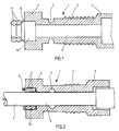
- the cable connector consists of the jacket 1 with an axial channel 2 for an ignition cable 3 (Fig. 2).
- This jacket 1 is subdivided into a plug-in sleeve 4, a shaft part 5 and a head part 6.
- the shaft part 5 and head part 6 are delimited from one another by an annular groove 7 (outside in FIG. 1; alternatively arranged inside in FIG. 2).
- a pair of rolling rings 9 merging into one another adjoins the head part 6 via a film 8.
- a ring shoulder 10 is arranged, which (FIG. 2) is intended for receiving the rolling rings 9.
- the inside diameter of the pair of rolling rings 9 is slightly smaller than the outside diameter of the ignition cable 3, so that when the ignition cable 3 is inserted into the channel 2, the pair of rolling rings 9 is inserted and pushed into the ring shoulder 10. The rolling rings 9 are pressed together and seal the adjoining channel 2 or the gap between the ignition cable 3 and the jacket 1 against moisture.
Landscapes
- Connector Housings Or Holding Contact Members (AREA)
- Spark Plugs (AREA)
- Ignition Installations For Internal Combustion Engines (AREA)
- Communication Cables (AREA)
- Details Of Connecting Devices For Male And Female Coupling (AREA)
Applications Claiming Priority (2)
| Application Number | Priority Date | Filing Date | Title |
|---|---|---|---|
| DE4101375 | 1991-01-18 | ||
| DE4101375A DE4101375C1 (enExample) | 1991-01-18 | 1991-01-18 |
Publications (2)
| Publication Number | Publication Date |
|---|---|
| EP0495377A1 EP0495377A1 (de) | 1992-07-22 |
| EP0495377B1 true EP0495377B1 (de) | 1995-04-12 |
Family
ID=6423262
Family Applications (1)
| Application Number | Title | Priority Date | Filing Date |
|---|---|---|---|
| EP92100187A Expired - Lifetime EP0495377B1 (de) | 1991-01-18 | 1992-01-08 | Kabelstecker für Zündkerzen |
Country Status (6)
| Country | Link |
|---|---|
| US (1) | US5181856A (enExample) |
| EP (1) | EP0495377B1 (enExample) |
| JP (1) | JPH04324275A (enExample) |
| AT (1) | ATE121228T1 (enExample) |
| DE (2) | DE4101375C1 (enExample) |
| ES (1) | ES2072022T3 (enExample) |
Families Citing this family (9)
| Publication number | Priority date | Publication date | Assignee | Title |
|---|---|---|---|---|
| DE4223818C1 (de) * | 1992-07-20 | 1993-11-25 | Pfisterer Elektrotech Karl | Elastisch verformbarer Isolier- und Dichtungskörper für Kabelstecker u. dgl. |
| JPH07153547A (ja) * | 1993-11-30 | 1995-06-16 | Yazaki Corp | プラグキャップ装置 |
| DE19611283C1 (de) * | 1996-03-22 | 1997-10-23 | Florian Virchow | Zündkerzenstecker für einen Verbrennungsmotor |
| JP3361704B2 (ja) * | 1996-10-25 | 2003-01-07 | 矢崎総業株式会社 | 点火プラグ用プラグキャップ |
| KR20030071212A (ko) * | 2002-02-28 | 2003-09-03 | (주)포스텍 | 일체형 점화케이블 어셈블리 와 그 제조방법 |
| DE102005056328B4 (de) * | 2005-11-25 | 2008-01-31 | Woco Industrietechnik Gmbh | Dichtung, insbesondere Dichtungsmatte, für mindestens einen elektrischen Steckverbinder |
| JP2011181247A (ja) * | 2010-02-26 | 2011-09-15 | Honda Motor Co Ltd | 防水コネクタ及びその組み付け方法 |
| EP2638603B1 (de) * | 2010-11-12 | 2021-05-26 | Hirschmann Automotive GmbH | Abdichtung der kontaktkammern gegen spritzmaterial (kunststoff) während des umspritzprozesses |
| DE102018108292B4 (de) | 2017-11-17 | 2023-05-11 | Borgwarner Ludwigsburg Gmbh | Verbindungsstecker zum Anschließen einer Zündspule an eine Zündkerze sowie Schutzrohr für einen Verbindungsstecker |
Family Cites Families (8)
| Publication number | Priority date | Publication date | Assignee | Title |
|---|---|---|---|---|
| US1898064A (en) * | 1927-12-28 | 1933-02-21 | William F Ridge | Insulator for spark plugs |
| US2904769A (en) * | 1953-07-10 | 1959-09-15 | Gen Motors Corp | Spark plug nipple |
| US2707723A (en) * | 1954-06-21 | 1955-05-03 | Walter H Moorhead | Self-locking flexible grommet |
| US2934668A (en) * | 1959-01-16 | 1960-04-26 | Gerald J Dall | Spark plug |
| GB8404107D0 (en) * | 1984-02-16 | 1984-03-21 | Allied Corp | Grommet for connectors |
| EP0288512A4 (en) * | 1986-10-17 | 1989-01-19 | Gold Securities Australia Ltd | PROTECTIVE SLEEVE FOR SPARK PLUG. |
| US4875875A (en) * | 1987-09-28 | 1989-10-24 | Brintec Corporation | Field terminable modular connector |
| FR2643194B1 (fr) * | 1989-02-14 | 1993-12-17 | Musorb Application Ferrites | Dispositif de connexion electrique d'un cable, notamment d'allumage, sur un plot |
-
1991
- 1991-01-18 DE DE4101375A patent/DE4101375C1/de not_active Expired - Lifetime
- 1991-12-13 US US07/807,301 patent/US5181856A/en not_active Expired - Fee Related
-
1992
- 1992-01-08 EP EP92100187A patent/EP0495377B1/de not_active Expired - Lifetime
- 1992-01-08 ES ES92100187T patent/ES2072022T3/es not_active Expired - Lifetime
- 1992-01-08 DE DE59201854T patent/DE59201854D1/de not_active Expired - Fee Related
- 1992-01-08 AT AT92100187T patent/ATE121228T1/de not_active IP Right Cessation
- 1992-01-14 JP JP4023337A patent/JPH04324275A/ja active Pending
Also Published As
| Publication number | Publication date |
|---|---|
| DE59201854D1 (de) | 1995-05-18 |
| DE4101375C1 (enExample) | 1992-04-30 |
| EP0495377A1 (de) | 1992-07-22 |
| ATE121228T1 (de) | 1995-04-15 |
| US5181856A (en) | 1993-01-26 |
| JPH04324275A (ja) | 1992-11-13 |
| ES2072022T3 (es) | 1995-07-01 |
Similar Documents
| Publication | Publication Date | Title |
|---|---|---|
| DE69206880T2 (de) | Dichtung für eine elektrische Leitungsschutzrohrkupplung und Kupplung mit dieser Dichtung | |
| DE69903152T2 (de) | Formschlauchkupplungsanordnung | |
| DE2554137A1 (de) | Wellendichtung, und verfahren zu ihrer herstellung | |
| DE10246354B4 (de) | Gleichlaufgelenkmanschette | |
| DE4101375C1 (enExample) | ||
| DE2927670A1 (de) | Dichtring | |
| EP3749886B1 (de) | Anschlussteil mit einer dichtung | |
| EP1308218B1 (de) | Kartuschenkolben mit Entlüftung | |
| WO1986004768A1 (fr) | Boitier forme d'au moins deux parties | |
| DE69208145T2 (de) | Kabelverschraubung | |
| EP0073748B1 (de) | Längsgeteilte druckfeste Kabelmuffe | |
| DE3942701C2 (de) | Verfahren zum Herstellen eines Staubverschlusses | |
| EP0402653A2 (de) | Kabeleinführungsdichtung | |
| EP0731541B1 (de) | Verschraubung, insb. für Kabel | |
| DE3730427A1 (de) | Anordnung zur befestigung von schlaeuchen an schlauchstutzen | |
| DE4404865C2 (de) | Spritzgieß-Verfahren sowie danach hergestellter Kükenhahn | |
| DE4134260C2 (de) | Hutmutter mit Knickschutz | |
| DE9308181U1 (de) | Anschlußarmatur für Rohre | |
| EP0347608B1 (de) | Dichtring | |
| DE1525461B1 (de) | Wellen- oder Stangendichtung | |
| DE3546435C2 (de) | Quetschverbinder | |
| DE102010018043A1 (de) | Stützring für einen Dichtring | |
| EP0844716B1 (de) | Kabelmuffe | |
| DE3042908A1 (de) | Dichtung zwischen gegeneinander drehbaren bauteilen | |
| EP1422429B1 (de) | Kugelgelenk |
Legal Events
| Date | Code | Title | Description |
|---|---|---|---|
| PUAI | Public reference made under article 153(3) epc to a published international application that has entered the european phase |
Free format text: ORIGINAL CODE: 0009012 |
|
| AK | Designated contracting states |
Kind code of ref document: A1 Designated state(s): AT DE ES FR GB IT SE |
|
| 17P | Request for examination filed |
Effective date: 19920808 |
|
| 17Q | First examination report despatched |
Effective date: 19921222 |
|
| GRAA | (expected) grant |
Free format text: ORIGINAL CODE: 0009210 |
|
| AK | Designated contracting states |
Kind code of ref document: B1 Designated state(s): AT DE ES FR GB IT SE |
|
| REF | Corresponds to: |
Ref document number: 121228 Country of ref document: AT Date of ref document: 19950415 Kind code of ref document: T |
|
| REF | Corresponds to: |
Ref document number: 59201854 Country of ref document: DE Date of ref document: 19950518 |
|
| ITF | It: translation for a ep patent filed | ||
| REG | Reference to a national code |
Ref country code: ES Ref legal event code: FG2A Ref document number: 2072022 Country of ref document: ES Kind code of ref document: T3 |
|
| GBT | Gb: translation of ep patent filed (gb section 77(6)(a)/1977) |
Effective date: 19950605 |
|
| ET | Fr: translation filed | ||
| PLBE | No opposition filed within time limit |
Free format text: ORIGINAL CODE: 0009261 |
|
| STAA | Information on the status of an ep patent application or granted ep patent |
Free format text: STATUS: NO OPPOSITION FILED WITHIN TIME LIMIT |
|
| 26N | No opposition filed | ||
| PGFP | Annual fee paid to national office [announced via postgrant information from national office to epo] |
Ref country code: DE Payment date: 19961212 Year of fee payment: 6 |
|
| PGFP | Annual fee paid to national office [announced via postgrant information from national office to epo] |
Ref country code: SE Payment date: 19961217 Year of fee payment: 6 |
|
| PGFP | Annual fee paid to national office [announced via postgrant information from national office to epo] |
Ref country code: GB Payment date: 19961230 Year of fee payment: 6 |
|
| PGFP | Annual fee paid to national office [announced via postgrant information from national office to epo] |
Ref country code: FR Payment date: 19970122 Year of fee payment: 6 Ref country code: AT Payment date: 19970122 Year of fee payment: 6 |
|
| PGFP | Annual fee paid to national office [announced via postgrant information from national office to epo] |
Ref country code: ES Payment date: 19970127 Year of fee payment: 6 |
|
| PG25 | Lapsed in a contracting state [announced via postgrant information from national office to epo] |
Ref country code: GB Free format text: LAPSE BECAUSE OF NON-PAYMENT OF DUE FEES Effective date: 19980108 Ref country code: AT Free format text: LAPSE BECAUSE OF NON-PAYMENT OF DUE FEES Effective date: 19980108 |
|
| PG25 | Lapsed in a contracting state [announced via postgrant information from national office to epo] |
Ref country code: SE Free format text: LAPSE BECAUSE OF NON-PAYMENT OF DUE FEES Effective date: 19980109 Ref country code: ES Free format text: LAPSE BECAUSE OF EXPIRATION OF PROTECTION Effective date: 19980109 |
|
| PG25 | Lapsed in a contracting state [announced via postgrant information from national office to epo] |
Ref country code: FR Free format text: THE PATENT HAS BEEN ANNULLED BY A DECISION OF A NATIONAL AUTHORITY Effective date: 19980131 |
|
| GBPC | Gb: european patent ceased through non-payment of renewal fee |
Effective date: 19980108 |
|
| PG25 | Lapsed in a contracting state [announced via postgrant information from national office to epo] |
Ref country code: DE Free format text: LAPSE BECAUSE OF NON-PAYMENT OF DUE FEES Effective date: 19981001 |
|
| EUG | Se: european patent has lapsed |
Ref document number: 92100187.1 |
|
| REG | Reference to a national code |
Ref country code: FR Ref legal event code: ST |
|
| REG | Reference to a national code |
Ref country code: ES Ref legal event code: FD2A Effective date: 20000601 |
|
| PG25 | Lapsed in a contracting state [announced via postgrant information from national office to epo] |
Ref country code: IT Free format text: LAPSE BECAUSE OF NON-PAYMENT OF DUE FEES;WARNING: LAPSES OF ITALIAN PATENTS WITH EFFECTIVE DATE BEFORE 2007 MAY HAVE OCCURRED AT ANY TIME BEFORE 2007. THE CORRECT EFFECTIVE DATE MAY BE DIFFERENT FROM THE ONE RECORDED. Effective date: 20050108 |