EP0495205B1 - Trennwand für Dusche mit verschwenkbarer Türe - Google Patents
Trennwand für Dusche mit verschwenkbarer Türe Download PDFInfo
- Publication number
- EP0495205B1 EP0495205B1 EP91121331A EP91121331A EP0495205B1 EP 0495205 B1 EP0495205 B1 EP 0495205B1 EP 91121331 A EP91121331 A EP 91121331A EP 91121331 A EP91121331 A EP 91121331A EP 0495205 B1 EP0495205 B1 EP 0495205B1
- Authority
- EP
- European Patent Office
- Prior art keywords
- door
- partition
- spacer
- hinge
- face
- Prior art date
- Legal status (The legal status is an assumption and is not a legal conclusion. Google has not performed a legal analysis and makes no representation as to the accuracy of the status listed.)
- Expired - Lifetime
Links
Images


Classifications
-
- A—HUMAN NECESSITIES
- A47—FURNITURE; DOMESTIC ARTICLES OR APPLIANCES; COFFEE MILLS; SPICE MILLS; SUCTION CLEANERS IN GENERAL
- A47K—SANITARY EQUIPMENT; ACCESSORIES THEREFOR, e.g. TOILET ACCESSORIES
- A47K3/00—Baths; Showers; Appurtenances therefor
- A47K3/28—Showers or bathing douches
- A47K3/30—Screens or collapsible cabinets for showers or baths
- A47K3/36—Articulated screens
-
- E—FIXED CONSTRUCTIONS
- E05—LOCKS; KEYS; WINDOW OR DOOR FITTINGS; SAFES
- E05D—HINGES OR SUSPENSION DEVICES FOR DOORS, WINDOWS OR WINGS
- E05D5/00—Construction of single parts, e.g. the parts for attachment
- E05D5/02—Parts for attachment, e.g. flaps
- E05D5/06—Bent flaps
-
- E—FIXED CONSTRUCTIONS
- E05—LOCKS; KEYS; WINDOW OR DOOR FITTINGS; SAFES
- E05D—HINGES OR SUSPENSION DEVICES FOR DOORS, WINDOWS OR WINGS
- E05D7/00—Hinges or pivots of special construction
- E05D7/04—Hinges adjustable relative to the wing or the frame
-
- A—HUMAN NECESSITIES
- A47—FURNITURE; DOMESTIC ARTICLES OR APPLIANCES; COFFEE MILLS; SPICE MILLS; SUCTION CLEANERS IN GENERAL
- A47K—SANITARY EQUIPMENT; ACCESSORIES THEREFOR, e.g. TOILET ACCESSORIES
- A47K3/00—Baths; Showers; Appurtenances therefor
- A47K3/28—Showers or bathing douches
- A47K3/30—Screens or collapsible cabinets for showers or baths
- A47K2003/307—Adjustable connections to the wall
-
- E—FIXED CONSTRUCTIONS
- E05—LOCKS; KEYS; WINDOW OR DOOR FITTINGS; SAFES
- E05D—HINGES OR SUSPENSION DEVICES FOR DOORS, WINDOWS OR WINGS
- E05D5/00—Construction of single parts, e.g. the parts for attachment
- E05D5/02—Parts for attachment, e.g. flaps
- E05D5/0246—Parts for attachment, e.g. flaps for attachment to glass panels
-
- E—FIXED CONSTRUCTIONS
- E05—LOCKS; KEYS; WINDOW OR DOOR FITTINGS; SAFES
- E05Y—INDEXING SCHEME ASSOCIATED WITH SUBCLASSES E05D AND E05F, RELATING TO CONSTRUCTION ELEMENTS, ELECTRIC CONTROL, POWER SUPPLY, POWER SIGNAL OR TRANSMISSION, USER INTERFACES, MOUNTING OR COUPLING, DETAILS, ACCESSORIES, AUXILIARY OPERATIONS NOT OTHERWISE PROVIDED FOR, APPLICATION THEREOF
- E05Y2800/00—Details, accessories and auxiliary operations not otherwise provided for
- E05Y2800/67—Materials; Strength alteration thereof
- E05Y2800/672—Glass
-
- E—FIXED CONSTRUCTIONS
- E05—LOCKS; KEYS; WINDOW OR DOOR FITTINGS; SAFES
- E05Y—INDEXING SCHEME ASSOCIATED WITH SUBCLASSES E05D AND E05F, RELATING TO CONSTRUCTION ELEMENTS, ELECTRIC CONTROL, POWER SUPPLY, POWER SIGNAL OR TRANSMISSION, USER INTERFACES, MOUNTING OR COUPLING, DETAILS, ACCESSORIES, AUXILIARY OPERATIONS NOT OTHERWISE PROVIDED FOR, APPLICATION THEREOF
- E05Y2900/00—Application of doors, windows, wings or fittings thereof
- E05Y2900/10—Application of doors, windows, wings or fittings thereof for buildings or parts thereof
- E05Y2900/114—Application of doors, windows, wings or fittings thereof for buildings or parts thereof for showers
Definitions
- the invention relates to a partition for shower with a pivotable door for opening according to the preamble of claim 1.
- Such a partition is known from EP-A-187 190.
- a supporting part is fastened by means of its holding part to a fixed wall part of the partition wall in such a way that the hinge part is adjustable in the horizontal direction and in the plane of the partition wall for adjusting the pivotable part of this partition wall, that is to say for adjusting the door.
- this door and its edge facing away from the hinge can therefore be easily adapted to unevenness, for example the wall of the building.
- a hinge with a carrying device for carrying and holding a movable element wherein one hinge part is formed on a fixed wall or building wall and the other hinge part is flat and acts indirectly on the pivotable part.
- this flat hinge part and the pivotable part there is still an angular support element, one angle leg of which rests on the pivotable part parallel to the hinge part, while the other angle leg runs parallel to the end face of the pivotable part and to the pivot axis of the hinge and via a retaining screw carries a terminal strip which engages in a C-shaped profile cutout on the pivotable element.
- the flat hinge part can be adjusted relative to the angle leg of this support structure by more or less thick documents, that is to say a certain adjustment can be carried out transversely to the hinge part.
- this construction is too complex for a pivotable door of a partition for showers and has cavities that could take up soap residue, hair or the like over time without being able to be cleaned easily.
- the adjustment is cumbersome because, by inserting different documents, it is necessary to try to determine when the correct adjustment has been made.
- a threaded section for changing the insertion depth is not only easy to manufacture and operate, but above all also permits continuous adjustment, so that adjustments with documents or the like of different thicknesses are avoided.
- Embodiments of the invention are the subject of claims 2 to 7.
- the aforementioned advantages can also be realized with a hinge which engages with a flat hinge part or flat piece and its flat side on the swing door.
- the adjustable spacer on the one hand and the fastening screw passing through it on the other hand can be countered against each other. This is also an advantage of using threads for adjustment and fastening.
- the door leaf which is formed in particular from a frameless glass pane, can be held by at least two spaced and independently adjustable hinges.
- the distance between the stop of the spacer and the door-side surface or end face of the hinge part can be at least partially encompassed by a cover, sleeve or ring which may extend over the edge of the end face of the hinge part, the cover being mounted in particular as a sliding ring on the hinge part or integrally with it the spacer can be connected.
- This distance between the front of the hinge part and the door leaf can thus be made invisible and also protected against the ingress of dirt.
- deformations for example perforations, flats or projections, can be provided on the circumference of the stop and / or the cover connected to it, for the engagement of a tool used to rotate the spacer.
- the insert part passing through the door-side hinge part can have a slot, cross slot, inner polygon and / or outer polygon on its side facing away from the door leaf for the attack of a tool.
- a very particularly useful and advantageous embodiment of a partition of the type mentioned, in which the hinge-side edge of the door projecting from the hinge to the building wall or fixed wall rests on a seal in the closed position may consist in the seal being adjustable in those directions and / or is slidably mounted, in which the door is adjustable for adjustment.
- the holding part facing away from the door can carry a transverse projection to the closing plane of the door leaf, preferably at right angles to the closed door leaf, against this protruding holding projection for detecting a mating projection of a holding strip for the seal which can be displaced in its orientation direction. If the door leaf is adjusted transversely to its plane occupied in the closed position, the holding strip for the seal on the holding projection can also be shifted in the corresponding direction and thus in turn adapted to the door leaf.
- the holding projection on the holding part for the door can be two-legged and a flange-like, projecting coupling strip of the holding strip for the seal can intervene in an adjustable and fixable manner, for example clamped, between the two, in particular, parallel legs.
- Brackets with appropriately oriented long slots and clamping screws passing through them or clamping screws acting directly on the surface of the coupling strip are conceivable.
- a further expedient configuration of the adaptation options for the seal can consist in the fact that the holding projection - with which the holding strip for the seal can be coupled - is arranged on a holder and is mounted displaceably and fixably in the horizontal direction of the holding part of the carrying device, for example as this holding part overlapping sleeve or sleeve is formed.
- the seal is not only adjustable transversely to the door leaf level to compensate for the adjustment of the door according to the invention on the front side of the hinge part, but in addition the seal can also be adjustable approximately parallel to the door plane in an approximately horizontal direction, in this direction too to compensate for adjustment movements of the door or to release the wall-side edge area of the door or partition for cleaning purposes, since a wall-side sealing area is generally difficult to access, but often allows deposits to accumulate over the years. If the entire sealing strip is moved out of its sealing area due to the horizontal adjustability and also the mobility possible at right angles to it, this and the sealing strip itself can be cleaned thoroughly.
- the hinge and / or the door have a catch and / or a stop at least for a defined closing or zero position of the door.
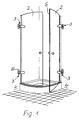
- a partition for differently designed showers and shower cubicles in the various exemplary embodiments, each designated 1, is provided with one or possibly two doors 2 which can be pivoted open and with a carrying device 3 for carrying and holding this door 2.
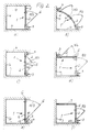
- the partition according to Fig.1 and acc. Fig. 2b consists for example of two arcuate, acc. the arrows Pf 1 u. Pf 2 doors 2 which can be pivoted away from one another and which are attached to two rectangular building walls 4 with the support devices 3 mentioned.
- the partition 1 acc. 2a consists of a pivotable flat door 2 and a fixed wall part 5 which is flush with the free end face 6 of the door 2 facing away from the carrying device 3 and relative to which the door 2 can be pivoted open in the direction of the arrow Pf 3.
- pivotable door 2 is provided in a building niche with three building walls 4.
- the shower according to FIG. 2c is also accommodated in a building niche with three building walls 4 which are at right angles to one another and has two flat doors 2 which are aligned with one another in the closed position and which, in turn, according to the arrows Pf 1 u.
- Pf 2 can be pivoted away from each other, as in the rest of the illustrated embodiments, the doors 2 can be pivoted outwards for opening and closed in the position shown for closing.
- FIGS. 2d and 2f each again show showers analogous to the solution according to FIG. 2b, which are arranged in a corner of a building from two mutually perpendicular building walls 4, in the case of FIG. 2d two doors 2 arranged at right angles to one another according to the arrows Pf 4 and Pf 5 can be pivoted outwards from the common corner of the shower cubicle formed by them, which leads to a particularly large entry.
- the end faces 6 of these two doors 2 must therefore be matched to one another very precisely.
- FIG. 2f is a similar embodiment to FIG. 2a, but a building wall is replaced by a fixed wall 7 standing at right angles to the partition wall 1 with the door 2.
- the door 2 can be pivoted outward in the direction of an arrow Pf 3 away from the fixed wall part 5 which is aligned with it in the closed position.
- FIG. 6 shows another solution in this connection, in which the partition 1 again has a pivotable door 2, the support device 3 of which, however, is connected to a fixed wall part 5 anchored to the building wall 4.
- the carrying device 3 engages on the one hand with a holding part 8 either on a fixed wall part 5 or on a building wall 4 and on the other hand via a hinge 9 and a hinge part 10 on the door 2, the hinge part 10 having an end face on the Door surface meets or is attached there in a manner to be described.
- the hinge 9 and the hinge part 10 can be adjusted transversely to the pivot axis 12 of the hinge 9 in the plane of the partition 2 by means of a substantially horizontal guide or rod 11.
- the guide rod 11 is in the embodiment shown in Figures 3 u. 6 is a bolt-like projection which slidably engages and can be fixed in a corresponding hole or bore in the holding part 8.
- the door 2 held in each case can be adapted to unevenness in the building wall 4 supporting it.
- such a distance adjustment also leads to a transverse offset of the door 2, so that the door leaf plane is adjusted and adjusted, and especially the edge 6 of such a door 2, in alignment with corresponding adjustments to support devices 3 or hinge parts 10 located one above the other can be brought to an opposite part.
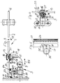
- FIGS. 3, 4 and 6 it can be seen that between the door end face of the hinge part 10 and the door 2 there is arranged a spacer 14 which is adjustable transversely to the door surface and serves as a stop for the door leaf and is part of the two-part design in both embodiments
- Fastening element 13 is, the second part of which is a pin 15 or bolt which penetrates the door 2 in the region of the spacer 14 and has a projection, head 16 or a nut which engages over the door surface facing away from the hinge 9.
- the door leaf of the door 2 is thus fixed between the spacer 14 acting as a stop and this head 16, so that an adjustment of the spacer 14 relative to the end face of the hinge part 10 brings about the desired relative adjustment of the door 2 relative to the hinge part 10 and the carrying device 3.
- a threaded bore 19 is provided for receiving a fastening screw passing through the spacer 14, which thus represents the aforementioned pin 15 with head 16.
- This threaded bore 19 goes from the bottom 20 of the perforation 17 into the depth of the hinge part 10.
- the door leaf is fixed in the position of use with the edges of an opening 21 passing through it at its fastening point between the spacer 14 and the head 16 of the screw.
- the fastening screw is loosened, that is to say the head 16 is not tightly fitting, the spacer 14 can therefore be adjusted and then fixed by tightening the screw and the head 16.
- the perforation 17 for the spacer 14 and its insertion part 18 is a blind hole which has an internal thread into which a corresponding threaded section of the insertion part 18 fits.
- the spacer 14 can thus be adjusted by rotating it in the axial direction of the perforation 17.
- the adjustable spacer 14 on the one hand and the fastening screw passing through it on the other hand are then countered to one another for fastening the set position of the door leaf.
- the door 2 and its door leaf are formed from a frameless glass pane.
- This is held in each case by two spaced and independently adjustable hinges 9 and hinge parts 10, so that different adjustments on the hinges 9 one above the other lead to corresponding alignment movements on the narrow sides 6 of the doors 2 and the two curved doors cooperating in FIG. 1 their end faces 6 can be adapted to each other from top to bottom, as shown in Fig. 2 b.
- the doors 2 of the other exemplary embodiments are adjusted in the same way.
- hinge 9 and / or the door 2 have a not shown in the drawings, for example realized and arranged within the hinge 9 or possibly a stop at least for the closing or zero position of the door.
- the door 2 is thus adjusted relative to the hinge part 10 and thus also relative to its zero position and latching.
- a cover 22 extending over the edge of the end face of the hinge part 10 is indicated in Fig. 3 that this cover 22 can be mounted as a sleeve or ring, namely as a sliding ring on the hinge part 10, while Fig. 4 shows a solution in which the cover 22 is integrally connected to the spacer 14, that is Adjustment movements follow automatically.
- the hinge-side edge 23 of the door 2, which projects beyond the hinge 9 towards the building wall 4 or fixed wall 5, can bear against a seal 24 in the closed position.
- the seal 24 is adjustable and / or slidably mounted in those directions in which the door 2 is adjustable for adjustment. This applies at least to the adjustment in the horizontal direction according to the double arrow Pf 6 (in FIG. 3) and above all in the direction of the double arrow Pf 7 running transversely to the door leaf plane.
- the holding projection 27 on the holding part 8 in the exemplary embodiment has two legs, and between the two parallel legs 30 a flange-like, projecting coupling strip of the holding strip 29 for the seal 24 is adjustable and can be fixed, preferably clamped, as the counter-projection 28. 5, a bore 31 can be seen on the leg 30, where a clamping screw for fixing the strip-shaped counter-projection 28 can be attached.
- the holding projection 27 - with its two parallel legs 30 - is in turn arranged on a holder 32 and this holder 32 is in the exemplary embodiment in the horizontal direction of the holding part 8 of the carrying device 3 mounted on this disc and again lockable.
- the holder 32 is designed as a sleeve or sleeve which overlaps this holding part 8 and on which the legs 30 project in continuation of the end faces.
- This sleeve or sleeve can also be fixed in its respective setting position with clamping screws.
- This adjustability has the advantage, above all, of being able to push the entire seal 24 away from the building wall 4 with a seal 33 additionally provided on the retaining strip 29, in order to be able to clean the often difficult to access seal area from deposits from time to time.
- FIGS. 8 to 10 each show a horizontal section of a door 2 in the region of a modified support device 3, in which the hinge part 10 on the door side is designed as a flat piece and is also shown in a horizontal section.
- This runs with a flat side parallel to the surface of the door leaf 2 and the adjusting device 13 with the plug-in part 18 is mounted transversely, in the exemplary embodiment at right angles to this flat side and to the door leaf plane, so as to be adjustable on this hinge part 10.
- the advantageous settings and adjustments of the door leaf level relative to the hinge or the carrying device 3 can also be carried out.
- the insert part 18 passes through the hinge part 10 over its entire cross section and the spacer 14 which is integrally connected to the insert part 18 in the exemplary embodiment with its end face directly or indirectly abuts the surface of the door leaf 2.
- the accessibility for a tool is improved in that the insertion part 18 protrudes from the hinge part 10 on the side facing away from the door 2 or is accessible from this side.
- the contact part of the spacer 14 can have an enlarged lateral or radial dimension relative to the contour of the insert part 18, in order to bring about a good contact surface on the door 2, which is often made of glass.
- the hinge part facing away from the door is fastened at right angles to the closed door and points away from it on the building wall 4, while in FIG. 9 this hinge part is oriented in the opposite direction to the arrangement in FIG. 8 and on which reaches past the wall-side edge of the door 2.
- the hinge 10 shows a hinge which is fastened to a fixed wall part 5 of the partition wall 1 of the shower cubicle with its support part 3 facing away from the pivoting door, for which purpose the hinge part 10 on the door side has an angle for bridging the overlapping area of the fixed wall part 5 and the closed door 2 .
- the support parts 3 or hinge straps connected to the building wall 4 or the fixed wall part 5 allow, if necessary, a height adjustment, so that in combination with the adjustability and adjustability of the door 2 according to the invention, virtually all inaccuracies can be compensated to a satisfactory extent and with usual tolerances transversely to the plane it occupies.
- the fastening screw 15 engages from the opposite side of the door 2 in the threaded bore 19 in the interior of the plug-in part 18 and thus enables the counter.
- the partition wall 1 for shower has a door 2 which can be swung open and which is held in any position by means of a carrying device 3.
- the carrying device 3 engages on the one hand with a holding part 8 on a fixed wall part 5 of the partition 1 or the shower cubicle or on a building wall 4 and on the other hand via a hinge 9 and a hinge part 10 on the door 2 in such a way that it has a surface hits the door surface.
- a fastening element 13 connected to this door-side hinge part 10 and its end face, which engages on the door 2, can be adjusted transversely to the door surface and relative to the hinge part 10 and thus also relative to the door-side surface or end face of the hinge part 10, that is, it a transverse adjustment of the door transversely to the plane spanned by it is possible relative to the hinge 9, so that when using two superposed hinges the door edge and its end face 6 can be adjusted to a corresponding counterpart, for example a second door 2 or a fixed wall part 5 .
- an adjustment in the direction of the door leaf plane can also be provided, for example by means of an essentially horizontal guide or rod 11 transverse to the pivot axis 12 of the door hinge 9.
Landscapes
- Health & Medical Sciences (AREA)
- Public Health (AREA)
- Engineering & Computer Science (AREA)
- Mechanical Engineering (AREA)
- Epidemiology (AREA)
- General Health & Medical Sciences (AREA)
- Hinges (AREA)
Applications Claiming Priority (2)
| Application Number | Priority Date | Filing Date | Title |
|---|---|---|---|
| DE4101363A DE4101363C1 (enExample) | 1991-01-18 | 1991-01-18 | |
| DE4101363 | 1991-01-18 |
Publications (2)
| Publication Number | Publication Date |
|---|---|
| EP0495205A1 EP0495205A1 (de) | 1992-07-22 |
| EP0495205B1 true EP0495205B1 (de) | 1995-04-19 |
Family
ID=6423251
Family Applications (1)
| Application Number | Title | Priority Date | Filing Date |
|---|---|---|---|
| EP91121331A Expired - Lifetime EP0495205B1 (de) | 1991-01-18 | 1991-12-12 | Trennwand für Dusche mit verschwenkbarer Türe |
Country Status (3)
| Country | Link |
|---|---|
| EP (1) | EP0495205B1 (enExample) |
| AT (1) | ATE121280T1 (enExample) |
| DE (2) | DE4101363C1 (enExample) |
Cited By (1)
| Publication number | Priority date | Publication date | Assignee | Title |
|---|---|---|---|---|
| EP1589170A2 (de) | 2004-04-20 | 2005-10-26 | Paul-Jean Munch | Modulares, multifunktionales Beschlagsystem für Duschabtrennungen |
Families Citing this family (13)
| Publication number | Priority date | Publication date | Assignee | Title |
|---|---|---|---|---|
| DE4231721C2 (de) * | 1992-09-22 | 1996-03-21 | Paul Jean Munch | Trennwand für Dusche mit einer Tragvorrichtung für eine verschwenkbare Türe |
| DE29602765U1 (de) * | 1996-02-16 | 1997-03-13 | Hoesch Metall + Kunststoffwerk GmbH & Co, 52372 Kreuzau | An unterschiedliche Breitenabmessungen anpaßbare Duschabtrennung |
| DE29700744U1 (de) * | 1997-01-17 | 1997-02-27 | Altura Leiden Holding B.V., Vianen | Duschtrennwand |
| DE19733039C1 (de) * | 1997-07-31 | 1999-03-04 | Dorma Gmbh & Co Kg | Band für rahmenlose Ganzglasduschen |
| DE19733037C1 (de) * | 1997-07-31 | 1999-03-04 | Dorma Gmbh & Co Kg | Band für rahmenlose Glastüren |
| DE29803966U1 (de) | 1998-03-07 | 1998-04-23 | Horst Breuer GmbH & Co., 56566 Neuwied | Duschkabine |
| DE29910496U1 (de) | 1999-06-16 | 1999-08-12 | Altura Leiden Holding B.V., Vianen | Duschtrennwand |
| EP1094184B1 (en) * | 1999-10-22 | 2001-12-12 | Gammastamp S.p.A. | A hinge for motor-vehicle doors, in particular for a hatchback |
| NL1015267C2 (nl) * | 2000-05-23 | 2001-11-26 | Keijsers Interieurbouw B V | Scharnierconstructie. |
| DE10049244C2 (de) * | 2000-09-28 | 2002-10-24 | Dorma Gmbh & Co Kg | Band |
| CN103556930B (zh) * | 2013-11-21 | 2015-04-08 | 张建锋 | 一种齿轮驱动的竖直部分具有弹性材料的密封仓门系统 |
| CN103556929B (zh) * | 2013-11-21 | 2015-04-22 | 黄娟娟 | 一种齿轮驱动的在门板空腔中设弹性材料的密封仓门系统 |
| CN113006644B (zh) * | 2021-04-19 | 2024-12-10 | 中国人民解放军32395部队 | 一种拼装式人防工程口部弧形防护结构及安装工艺 |
Family Cites Families (3)
| Publication number | Priority date | Publication date | Assignee | Title |
|---|---|---|---|---|
| FR2549518B1 (fr) * | 1983-07-22 | 1990-08-24 | Technal France | Penture reglable, notamment pour la fixation d'un volet sur des gonds preexistants |
| DE3423037A1 (de) * | 1984-06-22 | 1986-01-02 | Audi AG, 8070 Ingolstadt | Scharnier, insbesondere fuer eine dreidimensional einstellbare fahrzeugtuere |
| DE3445642A1 (de) * | 1984-12-14 | 1986-06-26 | Paul-Jean 7816 Münstertal Munch | Trennwand fuer dusche |
-
1991
- 1991-01-18 DE DE4101363A patent/DE4101363C1/de not_active Expired - Lifetime
- 1991-12-12 AT AT91121331T patent/ATE121280T1/de not_active IP Right Cessation
- 1991-12-12 DE DE59105263T patent/DE59105263D1/de not_active Expired - Fee Related
- 1991-12-12 EP EP91121331A patent/EP0495205B1/de not_active Expired - Lifetime
Cited By (1)
| Publication number | Priority date | Publication date | Assignee | Title |
|---|---|---|---|---|
| EP1589170A2 (de) | 2004-04-20 | 2005-10-26 | Paul-Jean Munch | Modulares, multifunktionales Beschlagsystem für Duschabtrennungen |
Also Published As
| Publication number | Publication date |
|---|---|
| ATE121280T1 (de) | 1995-05-15 |
| DE59105263D1 (de) | 1995-05-24 |
| EP0495205A1 (de) | 1992-07-22 |
| DE4101363C1 (enExample) | 1992-03-05 |
Similar Documents
| Publication | Publication Date | Title |
|---|---|---|
| DE4219681C2 (de) | Einstellbares Abhebescharnier | |
| EP0495205B1 (de) | Trennwand für Dusche mit verschwenkbarer Türe | |
| AT6962U1 (de) | Scharnier | |
| EP0384224B1 (de) | Führungsanordnung | |
| EP1653031B1 (de) | Falttürenscharnier | |
| DE4106235C1 (enExample) | ||
| EP0615716A1 (de) | Duschabtrennung mit einem Schwenkflügel | |
| DE4319422C1 (de) | Schwenktüre für Duschkabine | |
| EP0784956A1 (de) | Duschabtrennung | |
| EP1013210B1 (de) | Duschtrennwand | |
| EP3695748B1 (de) | Einbauschrankanordnung | |
| EP2208843B1 (de) | Scharnier für eine Tür | |
| DE29803884U1 (de) | Band für Türen, Fenster o.dgl. | |
| EP2108774B1 (de) | Beschlag | |
| DE3223590C2 (enExample) | ||
| EP1560996A1 (de) | Beschlaganordnung für glastüren | |
| DE8420711U1 (de) | Befestigungsvorrichtung für eine Dekorplatte an der Gerätetür eines Einbaukühlschrankes | |
| EP1038486B1 (de) | Bausatz für Duschabtrennungen | |
| EP1659246A1 (de) | Scharnierbeschlag für Fensterläden | |
| EP4018895B1 (de) | Haltevorrichtung zum befestigen eines abtrennungselements und abtrennungsanordnung mit einer haltevorrichtung | |
| DE2717169A1 (de) | Verstellbare aufhaengevorrichtung fuer moebelstuecke | |
| EP0721759A1 (de) | Duschabtrennung | |
| DE3109860C2 (enExample) | ||
| EP0510346A1 (de) | Beschlag zur Frontplattenbefestigung | |
| DE3600397C2 (enExample) |
Legal Events
| Date | Code | Title | Description |
|---|---|---|---|
| PUAI | Public reference made under article 153(3) epc to a published international application that has entered the european phase |
Free format text: ORIGINAL CODE: 0009012 |
|
| 17P | Request for examination filed |
Effective date: 19920521 |
|
| AK | Designated contracting states |
Kind code of ref document: A1 Designated state(s): AT BE CH DE ES FR GB IT LI NL |
|
| 17Q | First examination report despatched |
Effective date: 19940204 |
|
| GRAA | (expected) grant |
Free format text: ORIGINAL CODE: 0009210 |
|
| AK | Designated contracting states |
Kind code of ref document: B1 Designated state(s): AT BE CH DE ES FR GB IT LI NL |
|
| PG25 | Lapsed in a contracting state [announced via postgrant information from national office to epo] |
Ref country code: BE Effective date: 19950419 Ref country code: IT Free format text: LAPSE BECAUSE OF FAILURE TO SUBMIT A TRANSLATION OF THE DESCRIPTION OR TO PAY THE FEE WITHIN THE PRESCRIBED TIME-LIMIT;WARNING: LAPSES OF ITALIAN PATENTS WITH EFFECTIVE DATE BEFORE 2007 MAY HAVE OCCURRED AT ANY TIME BEFORE 2007. THE CORRECT EFFECTIVE DATE MAY BE DIFFERENT FROM THE ONE RECORDED. Effective date: 19950419 Ref country code: ES Free format text: THE PATENT HAS BEEN ANNULLED BY A DECISION OF A NATIONAL AUTHORITY Effective date: 19950419 Ref country code: NL Free format text: LAPSE BECAUSE OF NON-PAYMENT OF DUE FEES Effective date: 19950419 |
|
| REF | Corresponds to: |
Ref document number: 121280 Country of ref document: AT Date of ref document: 19950515 Kind code of ref document: T |
|
| ET | Fr: translation filed | ||
| REF | Corresponds to: |
Ref document number: 59105263 Country of ref document: DE Date of ref document: 19950524 |
|
| GBT | Gb: translation of ep patent filed (gb section 77(6)(a)/1977) |
Effective date: 19950612 |
|
| NLV1 | Nl: lapsed or annulled due to failure to fulfill the requirements of art. 29p and 29m of the patents act | ||
| PLBE | No opposition filed within time limit |
Free format text: ORIGINAL CODE: 0009261 |
|
| STAA | Information on the status of an ep patent application or granted ep patent |
Free format text: STATUS: NO OPPOSITION FILED WITHIN TIME LIMIT |
|
| 26N | No opposition filed | ||
| REG | Reference to a national code |
Ref country code: GB Ref legal event code: IF02 |
|
| PGFP | Annual fee paid to national office [announced via postgrant information from national office to epo] |
Ref country code: GB Payment date: 20041116 Year of fee payment: 14 |
|
| PG25 | Lapsed in a contracting state [announced via postgrant information from national office to epo] |
Ref country code: GB Free format text: LAPSE BECAUSE OF NON-PAYMENT OF DUE FEES Effective date: 20051212 |
|
| PGFP | Annual fee paid to national office [announced via postgrant information from national office to epo] |
Ref country code: AT Payment date: 20060315 Year of fee payment: 15 |
|
| PGFP | Annual fee paid to national office [announced via postgrant information from national office to epo] |
Ref country code: FR Payment date: 20060511 Year of fee payment: 15 |
|
| PGFP | Annual fee paid to national office [announced via postgrant information from national office to epo] |
Ref country code: CH Payment date: 20060519 Year of fee payment: 15 |
|
| PGFP | Annual fee paid to national office [announced via postgrant information from national office to epo] |
Ref country code: DE Payment date: 20060523 Year of fee payment: 15 |
|
| GBPC | Gb: european patent ceased through non-payment of renewal fee |
Effective date: 20051212 |
|
| PG25 | Lapsed in a contracting state [announced via postgrant information from national office to epo] |
Ref country code: CH Free format text: LAPSE BECAUSE OF NON-PAYMENT OF DUE FEES Effective date: 20061231 Ref country code: LI Free format text: LAPSE BECAUSE OF NON-PAYMENT OF DUE FEES Effective date: 20061231 |
|
| PG25 | Lapsed in a contracting state [announced via postgrant information from national office to epo] |
Ref country code: DE Free format text: LAPSE BECAUSE OF NON-PAYMENT OF DUE FEES Effective date: 20070703 |
|
| REG | Reference to a national code |
Ref country code: CH Ref legal event code: PL |
|
| REG | Reference to a national code |
Ref country code: FR Ref legal event code: ST Effective date: 20070831 |
|
| PG25 | Lapsed in a contracting state [announced via postgrant information from national office to epo] |
Ref country code: AT Free format text: LAPSE BECAUSE OF NON-PAYMENT OF DUE FEES Effective date: 20061212 |
|
| PG25 | Lapsed in a contracting state [announced via postgrant information from national office to epo] |
Ref country code: FR Free format text: LAPSE BECAUSE OF NON-PAYMENT OF DUE FEES Effective date: 20070102 |