EP0491908B1 - Dispositif d'ajustement de la position inclinee vers l'avant de la tige d'une chaussure de ski - Google Patents
Dispositif d'ajustement de la position inclinee vers l'avant de la tige d'une chaussure de ski Download PDFInfo
- Publication number
- EP0491908B1 EP0491908B1 EP91912417A EP91912417A EP0491908B1 EP 0491908 B1 EP0491908 B1 EP 0491908B1 EP 91912417 A EP91912417 A EP 91912417A EP 91912417 A EP91912417 A EP 91912417A EP 0491908 B1 EP0491908 B1 EP 0491908B1
- Authority
- EP
- European Patent Office
- Prior art keywords
- piece
- tensile
- damping element
- compressive
- shaft
- Prior art date
- Legal status (The legal status is an assumption and is not a legal conclusion. Google has not performed a legal analysis and makes no representation as to the accuracy of the status listed.)
- Expired - Lifetime
Links
- 238000013016 damping Methods 0.000 claims abstract description 79
- 239000004033 plastic Substances 0.000 claims abstract description 3
- 229920003023 plastic Polymers 0.000 claims abstract description 3
- 239000000463 material Substances 0.000 claims description 8
- 238000006073 displacement reaction Methods 0.000 claims description 5
- 230000006835 compression Effects 0.000 description 6
- 238000007906 compression Methods 0.000 description 6
- 239000006096 absorbing agent Substances 0.000 description 1
- 210000003423 ankle Anatomy 0.000 description 1
- 230000001419 dependent effect Effects 0.000 description 1
- 239000013536 elastomeric material Substances 0.000 description 1
- 230000036316 preload Effects 0.000 description 1
- 230000000717 retained effect Effects 0.000 description 1
- 230000035939 shock Effects 0.000 description 1
Images


Classifications
-
- A—HUMAN NECESSITIES
- A43—FOOTWEAR
- A43B—CHARACTERISTIC FEATURES OF FOOTWEAR; PARTS OF FOOTWEAR
- A43B5/00—Footwear for sporting purposes
- A43B5/04—Ski or like boots
- A43B5/0427—Ski or like boots characterised by type or construction details
- A43B5/0452—Adjustment of the forward inclination of the boot leg
- A43B5/0454—Adjustment of the forward inclination of the boot leg including flex control; Dampening means
- A43B5/0456—Adjustment of the forward inclination of the boot leg including flex control; Dampening means with the actuator being disposed at the rear side of the boot
Definitions
- the invention relates to a device for adjusting the template of the upper of a ski shoe with a pull and pressure piece, which is supported on the lower shell and the shaft or the cuff, the distance between the supporting surfaces interacting with the shaft or the cuff Tension and pressure piece for support on the lower shell is adjustable in the longitudinal direction of the tension and pressure piece.
- Devices for adjusting the presentation of the upper of a ski boot of the type mentioned are described, for example, in AT-PS 384 351.
- elastomeric components were arranged inside a housing designed in the manner of a shock absorber, the change in the basic setting for the presentation of the shaft being possible in that the component was completely disengaged from the anchors, whereupon by rotating the housing of the shock-absorbing element Component a sleeve was screwed to a bolt thread so that the effective length and thus the basic setting of the template could be changed.
- the damping component according to the Austrian patent 384 351 was a relatively complex and complex component, in which a fundamental change in the damping properties for the template limitation was only possible by completely dismantling the component and replacing damping elements or springs incorporated in the component.
- the invention now aims to provide a simple device which can be accommodated in the smallest space, of the type mentioned at the beginning, with which the possibility is created of the damping properties on the basis of a basic setting of the desired template of the shaft to change in a simple way. Particular importance is attached to the fact that not only a spring preload should be changeable, as is possible with a number of template limitations, but that the damping can actually be adapted to the respective needs without the need for large components.
- the device according to the invention consists essentially in the fact that the support surfaces interacting with the shaft or the sleeve interact with an upper and a lower stop surface on the shaft or the sleeve with the interposition of a damping element made of elastomeric plastic or rubber.
- the design is such that the supporting surfaces interacting with the shaft or the sleeve are formed by a nut, in particular a knurled nut, which can be rotated on a bolt thread of the tension and compression piece.
- a nut in particular a knurled nut
- the basic setting of the template are changed, the damping properties based on the selected basic setting only from the choice of the appropriate material for the intermediate damping element or from the orientation of the damping element in the free space between the rotatable nut and the counter-stop surfaces on the shaft or the cuff is dependent.
- the design is such that the damping element is designed as a component that can be plugged onto the tension and pressure piece from the rear with an opening for an actuator for the adjustment of the support surfaces on the tension and pressure piece, in particular the knurled nut .
- a damping element which can be plugged on from behind, can be removed from the back in a simple manner, if so desired, and replaced by a correspondingly small-sized damping element with different damping properties.
- Such a damping element can be fixed in a particularly simple manner in such a way that the damping element in the position plugged onto the pull and push piece interacts with a releasable locking member, in particular at least one locking pin which can be displaced parallel to the pull and push piece.
- the design of the releasable locking member as a displaceable locking pin can, in particular, if, as is a preferred development, two separately operable locking pins are arranged on the side of the pull and push piece, which are in recesses on the circumference of the damping element or in parallel to the pull and push piece Intervene bores of the damping element, are used to enable a folding movement of the attached damping element by moving a locking pin.
- the entire damping member can thus be pivoted about the axis of the second locking pin via the support surfaces on the tension and pressure piece, in particular on the knurled nut, so that when the position is pivoted out, a smaller cross section of the damping element is available for the damping than when pivoted in Location.
- a pivoting of the damping element thus causes a continuous change in the damping properties without changing the material of the damping element and after loosening the second displaceable locking pin, the damping element can be completely removed and replaced by a damping element with different material properties.
- the damping element is designed in such a way that the damping element above and below the support surfaces on the tension and compression piece consists of different materials with different elastic or damping properties, which means that the damping properties in the original and return directions can be changed in a simple manner by rotating the damping element by 180 ° and plugging this damping element again.
- the design is advantageously made such that the tension and pressure piece is articulatedly connected to an anchor piece in the lower shell, such Training in a simple manner also offers the possibility of completely unlocking the template limit in order to be able to pivot the shaft into a walking position.
- the design is advantageously made such that the anchor piece in the lower shell is axially displaceably mounted in a recess of the lower shell and that the anchor piece is in at least one displacement position is held by a releasable locking member, the releasable locking member of the anchor piece preferably being formed by a locking bolt which can be moved transversely to the axis of the anchor piece and which can be fixed in a position in engagement with a recess or opening in the anchor piece and in a position out of engagement with the anchor piece.
- the anchor piece can be freely moved in the axial direction, so that a further pivoting of the shaft in the direction of the reserve and thus an upright walking position can be adopted in a simple manner.
- the abutment surfaces for the support surfaces of the tension and pressure piece on the sleeve or the shaft can be formed in one piece with the shaft or the sleeve as flanges in a simple manner, which have a recess for the passage of the tension and pressure piece, whereby a closed Outer contour is formed after inserting the damping element.
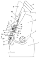
- FIG. 1 shows a partial side view of a ski boot with the device according to the invention for adjusting the template of the shaft; 2 shows a rear view of the ski boot according to FIG. 1 in the direction of arrow II of FIG. 1; 3 shows a side view of the damping element of FIG. 1 that can be plugged onto the pull and push piece; and Figure 4 is a view in the direction of arrow IV of Figure 3 on the damping element.
- a sleeve or a shaft 3 is pivotably articulated on a lower shell or shell 1 about an axis 2 in the ankle area.
- a support 4 is fixed on the cuff 3 and the inner boot of the ski boot is indicated by 5.
- a pulling and pushing piece 6 is provided, which is pivoted by a spindle 8 which is pivotable about an axis 7 on the shell 1 and is fixed in the shaft or in the sleeve 3 is formed with a bolt thread 9 and a knurled nut 10 screwable or adjustable on this bolt thread.
- the knurled nut 10 forms support surfaces 11 and 12 which, with the interposition of a damping element 13 made of elastomeric material or rubber, interact with an upper stop surface 14 and a lower stop surface 15 on the shaft or the sleeve 3.
- the pivot position of the shaft or the cuff 3 is adjusted relative to the shell 1.
- a corresponding damping of the movement of the shaft or the cuff 3 relative to the shell 1 in the respectively set template position is made possible by the damping element 13.
- the damping element 13 is plugged on from behind via the tension and pressure piece formed by the spindle drive 8 and the knurled nut 10 and has a recess 17 for the knurled nut to pass through, the end faces of which cooperate with the stop faces 11 and 12 on the knurled nut.
- the position of the damping element 13 is fixed by means of locking pins or bolts 18 which can be displaced essentially in the longitudinal direction of the pulling and pushing piece and which can be displaced by means of slides 19 in the rear region of the shaft or the sleeve 3 or the reserve support 4.
- the unlocked position is indicated by 18 'or 19'.
- the locking pins 18 cooperate with recesses 20 in the lateral area of the damping element 13.
- a locking bolt 22 interacts with a corresponding recess in the anchor piece or the sleeve 21 and, in one position, comes into engagement with the corresponding recess or opening in the anchor piece 21, thereby preventing axial displacement of the anchor piece and thus of the pulling and pushing piece .
- the bolt 22 disengages from the corresponding recess or opening and thus enables the anchor piece 21 to be axially displaceable, as a result of which a large range of pivoting of the shaft or the sleeve 3 relative to the shell 1 is possible.
- the locking bolt 22 is actuated via a lever 23, the fully drawn position of the lever 23 and the shaft or sleeve 3 corresponding to the locked position, while after the lever 23 is folded into the position 23 'indicated by the broken line, the locking bolt 22 except Engagement with the recess or opening of the sleeve or the anchor piece 21 and a pivoting of the shaft or the sleeve 3 in the position 3 'indicated by dashed lines, which facilitates walking with the ski shoe.
- the damping element 13 has areas of different damping properties or material properties designated by the designation “A” and “B” above and below the recess 17 for the knurled nut 10, so that with corresponding Choice of the material of the damping element 13 different damping properties for the original movement and the return movement can be achieved.
- a simple change in the damping properties can be made in that after loosening the locking bolt 18, the damping element is rotated by 180 ° and so the damping properties for the template or reserve movement are changed.
- a damping element can be replaced by another damping element with modified damping properties.
- FIG. 4 clearly shows how the damping element 13, which is adapted to the outer contour of the shaft or sleeve 3, with a recess 27 engages over the spindle of the tension and compression piece, which is not shown in more detail, the passage opening for the knurled nut again being indicated by 17 .
- the recesses cooperating with the locking pins 18 are designated.
- the locking bolts or pins 18, as indicated in FIG. 2, can be moved independently of one another in a suitable manner via the slide, so that after loosening a pin, the damping element 13 can be pivoted so that, with a corresponding fit of the damping element 13, by choice the size of the surfaces of the damping element 13 interacting with the stop surfaces 11, 12, 14 and 15, the damping properties can be further influenced.
Landscapes
- Health & Medical Sciences (AREA)
- General Health & Medical Sciences (AREA)
- Physical Education & Sports Medicine (AREA)
- Footwear And Its Accessory, Manufacturing Method And Apparatuses (AREA)
- Pipe Accessories (AREA)
- Sewage (AREA)
- Vehicle Body Suspensions (AREA)
Claims (9)
- Dispositif d'ajustement de la position inclinée vers l'avant de la tige (3) d'une chaussure de ski, comprenant un élément de traction et de pression (6) qui prend appui sur la coque inférieure (1) et la tige et respectivement la manchette (3), la distance entre les surfaces d'appui (11, 12) coopérant avec la tige et respectivement la manchette (3) et l'élément de traction et pression (6) pour l'appui sur la coque inférieure (1) étant réglable dans la direction longitudinale dudit élément de traction et de pression (6), caractérisé en ce que les surfaces d'appui (11, 12) coopérant avec la tige et respectivement la manchette (3) coopèrent, avec interposition d'un élément amortisseur (13) en matière plastique élastomère ou en caoutchouc, avec une surface d'arrêt supérieure et une surface d'arrêt inférieure (14, 15) prévues sur la tige et respectivement sur la manchette (3).
- Dispositif selon la revendication 1, caractérisé en ce que les surfaces d'appui (14, 15) coopérant avec la tige et respectivement avec la manchette (3) sont constituées par un écrou (3), notamment par un écrou moleté, tournant sur un filetage de boulon de l'élément de traction et de pression (6).
- Dispositif selon l'une des revendications 1 ou 2, caractérisé en ce que l'élément amortisseur (13) est réalisé sous la forme d'un élément emboîtable par l'arrière sur l'élément de traction et de pression (6) et muni d'une ouverture (27) pour un organe d'actionnement (10) pour le réglage des surfaces d'appui (14, 15) sur l'élément de traction et de pression (6), en particulier l'écrou moleté.
- Dispositif selon l'une des revendications 1, 2 ou 3, caractérisé en ce que, à l'état emboîté sur l'élément de traction et de pression (6), l'élément amortisseur (13) coopère avec un organe de verrouillage amovible, en particulier avec au moins une broche de verrouillage (18) déplaçable parallèlement à l'élément de traction et de pression (6).
- Dispositif selon l'une des revendications 1 à 4, caractérisé en ce que deux broches de verrouillage (18) pouvant être actionnées séparément sont disposées sur le côté de l'élément de traction et de pression (6), et s'engagent dans des évidements (20) sur la périphérie de l'élément amortisseur (13) ou dans des alésages de l'élément amortisseur (13) orientés parallèlement à l'élément de traction et de pression (6).
- Dispositif selon l'une des revendications 1 à 5, caractérisé en ce que l'élément amortisseur (13) est constitué, au-dessus et en dessous des surfaces d'appui (14, 15) sur l'élément de traction et de pression (6), de matériaux différents avec des propriétés d'élasticité et respectivement d'amortissement différentes.
- Dispositif selon l'une des revendications 1 à 6, caractérisé en ce que l'élément de traction et de pression (6) est articulé sur la coque inférieure (1) au moyen d'un élément d'ancrage (21).
- Dispositif selon l'une des revendications 1 à 7, caractérisé en ce que l'élément d'ancrage (21) dans la coque inférieure (1) est monté de manière axialement mobile dans un évidement de la coque inférieure (1), et que l'élément d'ancrage (21) est maintenu dans au moins une position de déplacement par un organe de verrouillage (22) amovible.
- Dispositif selon l'une des revendications 1 à 8, caractérisé en ce que l'organe de verrouillage (22) amovible de l'élément d'ancrage (21) est constitué par un boulon d'ancrage déplaçable transversalement à l'axe de l'élément d'ancrage (21), qui peut être bloqué dans une position d'engagement dans un évidement ou un perçage de l'élément d'ancrage (21) et dans une position dégagé de l'élément d'ancrage (21).
Applications Claiming Priority (3)
| Application Number | Priority Date | Filing Date | Title |
|---|---|---|---|
| AT0147790A AT398885B (de) | 1990-07-11 | 1990-07-11 | Einrichtung zur verstellung der vorlage des schaftes eines schischuhes |
| AT1477/90 | 1990-07-11 | ||
| PCT/AT1991/000085 WO1992000682A1 (fr) | 1990-07-11 | 1991-07-11 | Dispositif d'ajustement de la position inclinee vers l'avant de la tige d'une chaussure de ski |
Publications (2)
| Publication Number | Publication Date |
|---|---|
| EP0491908A1 EP0491908A1 (fr) | 1992-07-01 |
| EP0491908B1 true EP0491908B1 (fr) | 1994-10-12 |
Family
ID=3514744
Family Applications (1)
| Application Number | Title | Priority Date | Filing Date |
|---|---|---|---|
| EP91912417A Expired - Lifetime EP0491908B1 (fr) | 1990-07-11 | 1991-07-11 | Dispositif d'ajustement de la position inclinee vers l'avant de la tige d'une chaussure de ski |
Country Status (6)
| Country | Link |
|---|---|
| US (1) | US5276982A (fr) |
| EP (1) | EP0491908B1 (fr) |
| JP (1) | JPH0779722B2 (fr) |
| AT (2) | AT398885B (fr) |
| DE (1) | DE59103230D1 (fr) |
| WO (1) | WO1992000682A1 (fr) |
Families Citing this family (8)
| Publication number | Priority date | Publication date | Assignee | Title |
|---|---|---|---|---|
| AT398688B (de) * | 1991-12-02 | 1995-01-25 | Dynafit Skischuh Gmbh | Einstellsystem für skischuhe |
| US6283492B1 (en) | 1996-12-27 | 2001-09-04 | Noah W. Hale | Snowboard binding system and a snowboard step-in boot system with gradually increasing resistance |
| IT1297290B1 (it) * | 1997-11-05 | 1999-09-01 | Tecnica Spa | Perfezionamento relativo ai dispositivi di bloccaggio per calzature sportive in particolare per scarponi da sci. |
| WO2003008049A2 (fr) * | 2001-07-17 | 2003-01-30 | Fougere Raymond D | Fixation pour planche a neige avec tendeur determinant une position neutre |
| DE202008017053U1 (de) | 2008-12-23 | 2009-04-16 | SPIELMANN, Jörg | Schischuh und Umbausatz für einen Schischuh |
| ITTV20120053A1 (it) * | 2012-04-04 | 2013-10-05 | Scarpa Calzaturificio Spa | Scarpone da sci |
| US9833686B2 (en) * | 2015-01-29 | 2017-12-05 | Spark R&D Holdings, Llc | Splitboard boot binding system with adjustable highback |
| US10390589B2 (en) * | 2016-03-15 | 2019-08-27 | Nike, Inc. | Drive mechanism for automated footwear platform |
Family Cites Families (19)
| Publication number | Priority date | Publication date | Assignee | Title |
|---|---|---|---|---|
| US3543421A (en) * | 1969-02-17 | 1970-12-01 | Sports Technology | Adjustable stop for pivoted cuff |
| US3633291A (en) * | 1970-04-06 | 1972-01-11 | Domenico Caporicci | Ski boot having a pivoted top |
| DE2057094C3 (de) * | 1970-11-20 | 1973-11-22 | Altenburger Kg, 7893 Jestetten | Vorrichtung fur Skistiefel zur Begrenzung des Schwenkbereiches eines gegenüber einem Schaftunterteil ver schwenkbaren Schaftoberteils |
| US3945134A (en) * | 1974-09-13 | 1976-03-23 | Alpine Research, Inc. | Ski boot |
| CH587668A5 (fr) * | 1974-11-28 | 1977-05-13 | Salomon & Fils F | |
| US4039074A (en) * | 1975-11-05 | 1977-08-02 | Rapistan, Incorporated | Unscrambler for randomly arranged packages |
| FR2341283A1 (fr) * | 1976-02-20 | 1977-09-16 | Pinet Georges | Chaussure de ski |
| AT384351B (de) * | 1980-10-16 | 1987-11-10 | Koeflach Sportgeraete Gmbh | Skischuh |
| FR2498061B1 (fr) * | 1981-01-20 | 1985-05-31 | Articles Sport Cie Fse | Chaussure de ski |
| AT374667B (de) * | 1981-01-26 | 1984-05-25 | Dynafit Gmbh | Schischuh |
| IT8122767U1 (it) * | 1981-01-31 | 1982-07-31 | Nordica Spa | Dispositivo per regolare la flessibilita' particolarmente per scarponi da sci ad entrata posteriore |
| CH653531A5 (fr) * | 1983-08-29 | 1986-01-15 | Lange Int Sa | Chaussure de ski. |
| AT383475B (de) * | 1984-07-13 | 1987-07-10 | Lintner Dachstein Sportschuh | Skischuh |
| DE3504961A1 (de) * | 1984-11-23 | 1986-05-28 | Weinmann Gmbh & Co Kg Fahrrad- Und Motorrad-Teilefabrik, 7700 Singen | Skischuh |
| CH669718A5 (fr) * | 1986-06-06 | 1989-04-14 | Lange Int Sa | |
| FR2619684B1 (fr) * | 1987-09-02 | 1990-03-02 | Salomon Sa | Chaussure de ski alpin a tige articulee |
| AT397758B (de) * | 1988-09-09 | 1994-06-27 | Koeflach Sportgeraete Gmbh | Schischuh |
| CH677174A5 (fr) * | 1988-10-10 | 1991-04-30 | Lange Int Sa | |
| AT398364B (de) * | 1989-12-18 | 1994-11-25 | Dynafit Skischuh Gmbh | Dämpfungselement für skischuhe |
-
1990
- 1990-07-11 AT AT0147790A patent/AT398885B/de not_active IP Right Cessation
-
1991
- 1991-07-11 WO PCT/AT1991/000085 patent/WO1992000682A1/fr not_active Ceased
- 1991-07-11 JP JP3511823A patent/JPH0779722B2/ja not_active Expired - Lifetime
- 1991-07-11 EP EP91912417A patent/EP0491908B1/fr not_active Expired - Lifetime
- 1991-07-11 DE DE59103230T patent/DE59103230D1/de not_active Expired - Fee Related
- 1991-07-11 AT AT91912417T patent/ATE112665T1/de not_active IP Right Cessation
- 1991-07-11 US US07/838,197 patent/US5276982A/en not_active Expired - Fee Related
Also Published As
| Publication number | Publication date |
|---|---|
| DE59103230D1 (de) | 1994-11-17 |
| US5276982A (en) | 1994-01-11 |
| WO1992000682A1 (fr) | 1992-01-23 |
| ATE112665T1 (de) | 1994-10-15 |
| EP0491908A1 (fr) | 1992-07-01 |
| ATA147790A (de) | 1994-07-15 |
| AT398885B (de) | 1995-02-27 |
| JPH05501664A (ja) | 1993-04-02 |
| JPH0779722B2 (ja) | 1995-08-30 |
Similar Documents
| Publication | Publication Date | Title |
|---|---|---|
| DE3929505A1 (de) | Spindelmutteranordnung | |
| DE3020346C2 (fr) | ||
| DE3412139A1 (de) | Stellmechanismus | |
| DE102004037937B4 (de) | Türschloss, insbesondere mit Panikfunktion | |
| EP0491908B1 (fr) | Dispositif d'ajustement de la position inclinee vers l'avant de la tige d'une chaussure de ski | |
| DE19535667C2 (de) | Verstellvorrichtung für einen Fahrzeugscheinwerfer | |
| EP0117430B1 (fr) | Chaussure de ski | |
| DE69104857T2 (de) | Skibindung. | |
| DE3624152C1 (de) | Vorschubmechanik fuer ein Schreibgeraet | |
| DE602004013095T2 (de) | Snowboardbindung | |
| DE7239531U (de) | Sitz fuer industriefahrzeuge | |
| DE19737036B4 (de) | Lenkmodul eines Kraftfahrzeugs mit sowohl in ihrer Neigung als auch in der Länge verstellbarer Lenksäule | |
| DE102008034070A1 (de) | Schließzylinder mit federkraftunterstützter Zylinderkernrückstellung | |
| DE2264990A1 (de) | Zirkel, insbesondere kniezirkel | |
| DE3836683C1 (en) | Compass with adjustment spindle, especially rapid-adjustment compass | |
| DE102009038319B4 (de) | Stuhl | |
| DE2046809A1 (de) | Griffbeschlag für Fenster, insbesondere Dreh-Kipp-Fenster, Türen oder dergleichen | |
| DE948747C (de) | Elastische Gelenkanordnung | |
| EP0966588A1 (fr) | Dispositif comportant un element mobile | |
| DE741104C (de) | Fuellhalter mit Fuellkolben | |
| DE3513336A1 (de) | Fuehrungsmittel an buerodrehstuehlen | |
| DE2641583A1 (de) | Verstellbeschlag fuer fahrzeugsitze, insbesondere fuer die bezueglich ihrer neigung ein- und feststellbar mit dem sitzteil verbundene rueckenlehne | |
| DE2165226A1 (de) | Abblendbarer innenspiegel | |
| DE3048010A1 (de) | "drehmaschine, insbesondere horizontal-drehbank" | |
| EP0806534A2 (fr) | Crémone |
Legal Events
| Date | Code | Title | Description |
|---|---|---|---|
| PUAI | Public reference made under article 153(3) epc to a published international application that has entered the european phase |
Free format text: ORIGINAL CODE: 0009012 |
|
| AK | Designated contracting states |
Kind code of ref document: A1 Designated state(s): AT CH DE FR IT LI |
|
| 17P | Request for examination filed |
Effective date: 19920713 |
|
| RAP1 | Party data changed (applicant data changed or rights of an application transferred) |
Owner name: KOFLACH SPORT GESELLSCHAFT M.B.H. & CO. KG |
|
| 17Q | First examination report despatched |
Effective date: 19940125 |
|
| RAP1 | Party data changed (applicant data changed or rights of an application transferred) |
Owner name: KOFLACH SPORT GESELLSCHAFT M.B.H. & CO. KG |
|
| GRAA | (expected) grant |
Free format text: ORIGINAL CODE: 0009210 |
|
| AK | Designated contracting states |
Kind code of ref document: B1 Designated state(s): AT CH DE FR IT LI |
|
| REF | Corresponds to: |
Ref document number: 112665 Country of ref document: AT Date of ref document: 19941015 Kind code of ref document: T |
|
| ITF | It: translation for a ep patent filed | ||
| REF | Corresponds to: |
Ref document number: 59103230 Country of ref document: DE Date of ref document: 19941117 |
|
| ET | Fr: translation filed | ||
| PG25 | Lapsed in a contracting state [announced via postgrant information from national office to epo] |
Ref country code: AT Effective date: 19950711 |
|
| PLBE | No opposition filed within time limit |
Free format text: ORIGINAL CODE: 0009261 |
|
| STAA | Information on the status of an ep patent application or granted ep patent |
Free format text: STATUS: NO OPPOSITION FILED WITHIN TIME LIMIT |
|
| 26N | No opposition filed | ||
| REG | Reference to a national code |
Ref country code: CH Ref legal event code: PFA Free format text: KOFLACH SPORT GESELLSCHAFT MBH & CO. KG TRANSFER- KOFLACH SPORT GESELLSCHAFT M.B.H. * KOFLACH SPORT GESELLSCHAFT M.B.H. TRANSFER- KOFLACH SPORT GESELLSCHAFT M.B.H. |
|
| PGFP | Annual fee paid to national office [announced via postgrant information from national office to epo] |
Ref country code: FR Payment date: 19970721 Year of fee payment: 7 |
|
| PGFP | Annual fee paid to national office [announced via postgrant information from national office to epo] |
Ref country code: DE Payment date: 19970930 Year of fee payment: 7 |
|
| REG | Reference to a national code |
Ref country code: FR Ref legal event code: TP Ref country code: FR Ref legal event code: CA |
|
| PGFP | Annual fee paid to national office [announced via postgrant information from national office to epo] |
Ref country code: CH Payment date: 19980708 Year of fee payment: 8 |
|
| REG | Reference to a national code |
Ref country code: FR Ref legal event code: RM |
|
| PG25 | Lapsed in a contracting state [announced via postgrant information from national office to epo] |
Ref country code: FR Free format text: LAPSE BECAUSE OF NON-PAYMENT OF DUE FEES Effective date: 19990331 |
|
| PG25 | Lapsed in a contracting state [announced via postgrant information from national office to epo] |
Ref country code: DE Free format text: LAPSE BECAUSE OF NON-PAYMENT OF DUE FEES Effective date: 19990501 |
|
| REG | Reference to a national code |
Ref country code: FR Ref legal event code: ST |
|
| PG25 | Lapsed in a contracting state [announced via postgrant information from national office to epo] |
Ref country code: LI Free format text: LAPSE BECAUSE OF NON-PAYMENT OF DUE FEES Effective date: 19990731 Ref country code: CH Free format text: LAPSE BECAUSE OF NON-PAYMENT OF DUE FEES Effective date: 19990731 |
|
| REG | Reference to a national code |
Ref country code: CH Ref legal event code: PL |
|
| PG25 | Lapsed in a contracting state [announced via postgrant information from national office to epo] |
Ref country code: IT Free format text: LAPSE BECAUSE OF NON-PAYMENT OF DUE FEES;WARNING: LAPSES OF ITALIAN PATENTS WITH EFFECTIVE DATE BEFORE 2007 MAY HAVE OCCURRED AT ANY TIME BEFORE 2007. THE CORRECT EFFECTIVE DATE MAY BE DIFFERENT FROM THE ONE RECORDED. Effective date: 20050711 |