EP0491908B1 - Device for adjusting the angle of the shaft of a ski boot - Google Patents
Device for adjusting the angle of the shaft of a ski boot Download PDFInfo
- Publication number
- EP0491908B1 EP0491908B1 EP91912417A EP91912417A EP0491908B1 EP 0491908 B1 EP0491908 B1 EP 0491908B1 EP 91912417 A EP91912417 A EP 91912417A EP 91912417 A EP91912417 A EP 91912417A EP 0491908 B1 EP0491908 B1 EP 0491908B1
- Authority
- EP
- European Patent Office
- Prior art keywords
- piece
- tensile
- damping element
- compressive
- shaft
- Prior art date
- Legal status (The legal status is an assumption and is not a legal conclusion. Google has not performed a legal analysis and makes no representation as to the accuracy of the status listed.)
- Expired - Lifetime
Links
- 238000013016 damping Methods 0.000 claims abstract description 79
- 239000004033 plastic Substances 0.000 claims abstract description 3
- 229920003023 plastic Polymers 0.000 claims abstract description 3
- 239000000463 material Substances 0.000 claims description 8
- 238000006073 displacement reaction Methods 0.000 claims description 5
- 230000006835 compression Effects 0.000 description 6
- 238000007906 compression Methods 0.000 description 6
- 239000006096 absorbing agent Substances 0.000 description 1
- 210000003423 ankle Anatomy 0.000 description 1
- 230000001419 dependent effect Effects 0.000 description 1
- 239000013536 elastomeric material Substances 0.000 description 1
- 230000036316 preload Effects 0.000 description 1
- 230000000717 retained effect Effects 0.000 description 1
- 230000035939 shock Effects 0.000 description 1
Images


Classifications
-
- A—HUMAN NECESSITIES
- A43—FOOTWEAR
- A43B—CHARACTERISTIC FEATURES OF FOOTWEAR; PARTS OF FOOTWEAR
- A43B5/00—Footwear for sporting purposes
- A43B5/04—Ski or like boots
- A43B5/0427—Ski or like boots characterised by type or construction details
- A43B5/0452—Adjustment of the forward inclination of the boot leg
- A43B5/0454—Adjustment of the forward inclination of the boot leg including flex control; Dampening means
- A43B5/0456—Adjustment of the forward inclination of the boot leg including flex control; Dampening means with the actuator being disposed at the rear side of the boot
Definitions
- the invention relates to a device for adjusting the template of the upper of a ski shoe with a pull and pressure piece, which is supported on the lower shell and the shaft or the cuff, the distance between the supporting surfaces interacting with the shaft or the cuff Tension and pressure piece for support on the lower shell is adjustable in the longitudinal direction of the tension and pressure piece.
- Devices for adjusting the presentation of the upper of a ski boot of the type mentioned are described, for example, in AT-PS 384 351.
- elastomeric components were arranged inside a housing designed in the manner of a shock absorber, the change in the basic setting for the presentation of the shaft being possible in that the component was completely disengaged from the anchors, whereupon by rotating the housing of the shock-absorbing element Component a sleeve was screwed to a bolt thread so that the effective length and thus the basic setting of the template could be changed.
- the damping component according to the Austrian patent 384 351 was a relatively complex and complex component, in which a fundamental change in the damping properties for the template limitation was only possible by completely dismantling the component and replacing damping elements or springs incorporated in the component.
- the invention now aims to provide a simple device which can be accommodated in the smallest space, of the type mentioned at the beginning, with which the possibility is created of the damping properties on the basis of a basic setting of the desired template of the shaft to change in a simple way. Particular importance is attached to the fact that not only a spring preload should be changeable, as is possible with a number of template limitations, but that the damping can actually be adapted to the respective needs without the need for large components.
- the device according to the invention consists essentially in the fact that the support surfaces interacting with the shaft or the sleeve interact with an upper and a lower stop surface on the shaft or the sleeve with the interposition of a damping element made of elastomeric plastic or rubber.
- the design is such that the supporting surfaces interacting with the shaft or the sleeve are formed by a nut, in particular a knurled nut, which can be rotated on a bolt thread of the tension and compression piece.
- a nut in particular a knurled nut
- the basic setting of the template are changed, the damping properties based on the selected basic setting only from the choice of the appropriate material for the intermediate damping element or from the orientation of the damping element in the free space between the rotatable nut and the counter-stop surfaces on the shaft or the cuff is dependent.
- the design is such that the damping element is designed as a component that can be plugged onto the tension and pressure piece from the rear with an opening for an actuator for the adjustment of the support surfaces on the tension and pressure piece, in particular the knurled nut .
- a damping element which can be plugged on from behind, can be removed from the back in a simple manner, if so desired, and replaced by a correspondingly small-sized damping element with different damping properties.
- Such a damping element can be fixed in a particularly simple manner in such a way that the damping element in the position plugged onto the pull and push piece interacts with a releasable locking member, in particular at least one locking pin which can be displaced parallel to the pull and push piece.
- the design of the releasable locking member as a displaceable locking pin can, in particular, if, as is a preferred development, two separately operable locking pins are arranged on the side of the pull and push piece, which are in recesses on the circumference of the damping element or in parallel to the pull and push piece Intervene bores of the damping element, are used to enable a folding movement of the attached damping element by moving a locking pin.
- the entire damping member can thus be pivoted about the axis of the second locking pin via the support surfaces on the tension and pressure piece, in particular on the knurled nut, so that when the position is pivoted out, a smaller cross section of the damping element is available for the damping than when pivoted in Location.
- a pivoting of the damping element thus causes a continuous change in the damping properties without changing the material of the damping element and after loosening the second displaceable locking pin, the damping element can be completely removed and replaced by a damping element with different material properties.
- the damping element is designed in such a way that the damping element above and below the support surfaces on the tension and compression piece consists of different materials with different elastic or damping properties, which means that the damping properties in the original and return directions can be changed in a simple manner by rotating the damping element by 180 ° and plugging this damping element again.
- the design is advantageously made such that the tension and pressure piece is articulatedly connected to an anchor piece in the lower shell, such Training in a simple manner also offers the possibility of completely unlocking the template limit in order to be able to pivot the shaft into a walking position.
- the design is advantageously made such that the anchor piece in the lower shell is axially displaceably mounted in a recess of the lower shell and that the anchor piece is in at least one displacement position is held by a releasable locking member, the releasable locking member of the anchor piece preferably being formed by a locking bolt which can be moved transversely to the axis of the anchor piece and which can be fixed in a position in engagement with a recess or opening in the anchor piece and in a position out of engagement with the anchor piece.
- the anchor piece can be freely moved in the axial direction, so that a further pivoting of the shaft in the direction of the reserve and thus an upright walking position can be adopted in a simple manner.
- the abutment surfaces for the support surfaces of the tension and pressure piece on the sleeve or the shaft can be formed in one piece with the shaft or the sleeve as flanges in a simple manner, which have a recess for the passage of the tension and pressure piece, whereby a closed Outer contour is formed after inserting the damping element.
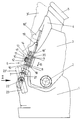
- FIG. 1 shows a partial side view of a ski boot with the device according to the invention for adjusting the template of the shaft; 2 shows a rear view of the ski boot according to FIG. 1 in the direction of arrow II of FIG. 1; 3 shows a side view of the damping element of FIG. 1 that can be plugged onto the pull and push piece; and Figure 4 is a view in the direction of arrow IV of Figure 3 on the damping element.
- a sleeve or a shaft 3 is pivotably articulated on a lower shell or shell 1 about an axis 2 in the ankle area.
- a support 4 is fixed on the cuff 3 and the inner boot of the ski boot is indicated by 5.
- a pulling and pushing piece 6 is provided, which is pivoted by a spindle 8 which is pivotable about an axis 7 on the shell 1 and is fixed in the shaft or in the sleeve 3 is formed with a bolt thread 9 and a knurled nut 10 screwable or adjustable on this bolt thread.
- the knurled nut 10 forms support surfaces 11 and 12 which, with the interposition of a damping element 13 made of elastomeric material or rubber, interact with an upper stop surface 14 and a lower stop surface 15 on the shaft or the sleeve 3.
- the pivot position of the shaft or the cuff 3 is adjusted relative to the shell 1.
- a corresponding damping of the movement of the shaft or the cuff 3 relative to the shell 1 in the respectively set template position is made possible by the damping element 13.
- the damping element 13 is plugged on from behind via the tension and pressure piece formed by the spindle drive 8 and the knurled nut 10 and has a recess 17 for the knurled nut to pass through, the end faces of which cooperate with the stop faces 11 and 12 on the knurled nut.
- the position of the damping element 13 is fixed by means of locking pins or bolts 18 which can be displaced essentially in the longitudinal direction of the pulling and pushing piece and which can be displaced by means of slides 19 in the rear region of the shaft or the sleeve 3 or the reserve support 4.
- the unlocked position is indicated by 18 'or 19'.
- the locking pins 18 cooperate with recesses 20 in the lateral area of the damping element 13.
- a locking bolt 22 interacts with a corresponding recess in the anchor piece or the sleeve 21 and, in one position, comes into engagement with the corresponding recess or opening in the anchor piece 21, thereby preventing axial displacement of the anchor piece and thus of the pulling and pushing piece .
- the bolt 22 disengages from the corresponding recess or opening and thus enables the anchor piece 21 to be axially displaceable, as a result of which a large range of pivoting of the shaft or the sleeve 3 relative to the shell 1 is possible.
- the locking bolt 22 is actuated via a lever 23, the fully drawn position of the lever 23 and the shaft or sleeve 3 corresponding to the locked position, while after the lever 23 is folded into the position 23 'indicated by the broken line, the locking bolt 22 except Engagement with the recess or opening of the sleeve or the anchor piece 21 and a pivoting of the shaft or the sleeve 3 in the position 3 'indicated by dashed lines, which facilitates walking with the ski shoe.
- the damping element 13 has areas of different damping properties or material properties designated by the designation “A” and “B” above and below the recess 17 for the knurled nut 10, so that with corresponding Choice of the material of the damping element 13 different damping properties for the original movement and the return movement can be achieved.
- a simple change in the damping properties can be made in that after loosening the locking bolt 18, the damping element is rotated by 180 ° and so the damping properties for the template or reserve movement are changed.
- a damping element can be replaced by another damping element with modified damping properties.
- FIG. 4 clearly shows how the damping element 13, which is adapted to the outer contour of the shaft or sleeve 3, with a recess 27 engages over the spindle of the tension and compression piece, which is not shown in more detail, the passage opening for the knurled nut again being indicated by 17 .
- the recesses cooperating with the locking pins 18 are designated.
- the locking bolts or pins 18, as indicated in FIG. 2, can be moved independently of one another in a suitable manner via the slide, so that after loosening a pin, the damping element 13 can be pivoted so that, with a corresponding fit of the damping element 13, by choice the size of the surfaces of the damping element 13 interacting with the stop surfaces 11, 12, 14 and 15, the damping properties can be further influenced.
Landscapes
- Health & Medical Sciences (AREA)
- General Health & Medical Sciences (AREA)
- Physical Education & Sports Medicine (AREA)
- Footwear And Its Accessory, Manufacturing Method And Apparatuses (AREA)
- Pipe Accessories (AREA)
- Sewage (AREA)
- Vehicle Body Suspensions (AREA)
Abstract
Description
Die Erfindung bezieht sich auf eine Einrichtung zur Verstellung der Vorlage des Schaftes eines Schischuhes mit einem Zug- und Druckstück, welches an der Unterschale und dem Schaft bzw. der Manschette abgestützt ist, wobei der Abstand der mit dem Schaft bzw. der Manschette zusammenwirkenden Stutzflächen am Zug- und Druckstück zur Abstützung an der Unterschale in Längsrichtung des Zug- und Druckstückes verstellbar ist.The invention relates to a device for adjusting the template of the upper of a ski shoe with a pull and pressure piece, which is supported on the lower shell and the shaft or the cuff, the distance between the supporting surfaces interacting with the shaft or the cuff Tension and pressure piece for support on the lower shell is adjustable in the longitudinal direction of the tension and pressure piece.
Einrichtungen zur Verstellung der Vorlage des Schaftes eines Schischuhes der eingangs genannten Art sind beispielsweise in der AT-PS 384 351 beschrieben. Bei dieser bekannten Ausbildung wurden im Inneren eines nach Art eines Stoßdämpfers ausgebildeten Gehäuses elastomere Bauteile angeordnet, wobei die Veränderung der Grundeinstellung für die Vorlage des Schaftes dadurch möglich wurde, daß der Bauteil zur Gänze aus den Verankerungen ausgeklinkt wurde, worauf durch Drehen des Gehäuses des stoßdämpfenden Bauteiles eine Hülse an einem Bolzengewinde derart verschraubt wurde, daß die wirksame Länge und damit die Grundeinstellung der Vorlage verändert werden konnte. Insgesamt stellte der Dämpfungsbauteil gemäß der österreichischen Patentschrift 384 351 einen relativ aufwendigen und komplizierten Bauteil dar, bei welchem eine grundsätzliche Änderung der Dämpfungseigenschaften für die Vorlagebegrenzung nur durch vollständiges Zerlegen des Bauteiles und Ersatz von Dämpfungselementen bzw. in dem Bauteil aufgenommenen Federn möglich war.Devices for adjusting the presentation of the upper of a ski boot of the type mentioned are described, for example, in AT-PS 384 351. In this known design, elastomeric components were arranged inside a housing designed in the manner of a shock absorber, the change in the basic setting for the presentation of the shaft being possible in that the component was completely disengaged from the anchors, whereupon by rotating the housing of the shock-absorbing element Component a sleeve was screwed to a bolt thread so that the effective length and thus the basic setting of the template could be changed. Overall, the damping component according to the Austrian patent 384 351 was a relatively complex and complex component, in which a fundamental change in the damping properties for the template limitation was only possible by completely dismantling the component and replacing damping elements or springs incorporated in the component.
Die Erfindung zielt nun darauf ab, eine einfache und auf kleinstem Raum unterbringbare Einrichtung der eingangs genannten Art zu schaffen, mit welcher die Möglichkeit geschaffen wird, die Dämpfungseigenschaften ausgehend von einer Grundeinstellung der gewünschten Vorlage des Schaftes in einfacher Weise zu verändern. Besondere Bedeutung wird dabei dem Umstand zugemessen, daß nicht etwa nur eine Federvorspannung veränderbar sein soll, wie dies bei einer Reihe von Vorlagebegrenzungen möglich ist, sondern daß tatsächlich die Dämpfung den jeweiligen Bedürfnissen exakt angepaßt werden kann, ohne daß hiefür großbauende Bauteile erforderlich werden. Zur Lösung dieser Aufgabe besteht die erfindungsgemäße Einrichtung im wesentlichen darin, daß die mit dem Schaft bzw. der Manschette zusammenwirkenden Stützflächen unter Zwischenschaltung eines Dämpfungselementes aus elastomerem Kunststoff oder Gummi mit einer oberen und einer unteren Anschlagfläche am Schaft bzw. der Manschette zusammenwirken. Dadurch, daß ein relativ kleinbauendes Dämpfungselement unmittelbar zwischen Anschlagflächen am Schaft bzw. der Manschette und Stützflächen des Zug- und Druckstückes angeordnet wird, wird ein in einfacher Weise zugängliches und austauschbares Dämpfungselement ermöglicht, wobei dadurch, daß die Stützflächen am Zug- bzw. Druckstück in Längsrichtung des Zug- und Druckstückes verstellbar sind, eine einfache Vorlagenverstellung in konventioneller Weise ermöglicht wird. Die Anordnung eines leicht zugänglichen Dämpfungselementes unmittelbar zwischen den miteinander zusammenwirkenden Flächen beeinträchtigt hiebei in keiner Weise die einfache Verstellung der Vorlage in konventioneller Weise, wobei zusätzlich durch die Zwischenschaltung eines derartigen Dämpfungsbauteiles eine leichte Veränderung der Dämpfungseigenschaften durch Austausch des Bauteiles oder andere Orientierung des Bauteiles ermöglicht wird.The invention now aims to provide a simple device which can be accommodated in the smallest space, of the type mentioned at the beginning, with which the possibility is created of the damping properties on the basis of a basic setting of the desired template of the shaft to change in a simple way. Particular importance is attached to the fact that not only a spring preload should be changeable, as is possible with a number of template limitations, but that the damping can actually be adapted to the respective needs without the need for large components. To achieve this object, the device according to the invention consists essentially in the fact that the support surfaces interacting with the shaft or the sleeve interact with an upper and a lower stop surface on the shaft or the sleeve with the interposition of a damping element made of elastomeric plastic or rubber. The fact that a relatively small-sized damping element is arranged directly between the stop surfaces on the shaft or the cuff and the support surfaces of the tension and compression piece, allows an easily accessible and interchangeable damping element, whereby the support surfaces on the tension or compression piece in Longitudinal direction of the tension and compression piece are adjustable, a simple template adjustment is made possible in a conventional manner. The arrangement of an easily accessible damping element directly between the interacting surfaces does not in any way impair the simple adjustment of the template in a conventional manner, with the interposition of such a damping component also allowing the damping properties to be changed slightly by replacing the component or other orientation of the component .
Gemäß einer bevorzugten Weiterbildung der erfindungsgemäßen Einrichtung ist die Ausbildung so getroffen, daß die mit dem Schaft bzw. der Manschette zusammenwirkenden Stützflächen von einer auf einem Bolzengewinde des Zug- und Druckstückes verdrehbaren Mutter, insbesondere Rändelmutter, gebildet sind. Auf diese Weise kann, wie von anderen Vorlageverstellungen bekannt, durch einfaches Verdrehen einer Mutter, insbesondere Rändelmutter, die Grundeinstellung der Vorlage verändert werden, wobei die Dämpfungseigenschaften ausgehend von der jeweils gewählten Grundeinstellung nur mehr von der Wahl des entsprechenden Materials für das zwischengeschaltete Dämpfungselement bzw. von der Orientierung des Dämpfungselementes in dem freien Raum zwischen der verdrehbaren Mutter und den Gegenanschlagsflächen am Schaft bzw. der Manschette abhängig ist.According to a preferred development of the device according to the invention, the design is such that the supporting surfaces interacting with the shaft or the sleeve are formed by a nut, in particular a knurled nut, which can be rotated on a bolt thread of the tension and compression piece. In this way, as is known from other template adjustments, by simply turning a nut, in particular Knurled nut, the basic setting of the template are changed, the damping properties based on the selected basic setting only from the choice of the appropriate material for the intermediate damping element or from the orientation of the damping element in the free space between the rotatable nut and the counter-stop surfaces on the shaft or the cuff is dependent.
Gemäß einer vorteilhaften Weiterbildung der erfindungsgemäßen Einrichtung ist die Ausbildung so getroffen, daß das Dämpfungselement als auf das Zug- und Druckstück von hinten aufsteckbarer Bauteil mit einer Öffnung für ein Betätigungsglied für die Verstellung der Stützflächen am Zug- und Druckstück, insbesondere die Rändelmutter, ausgebildet ist. Ein derartiges, von hinten aufsteckbares Dämpfungselement kann in einfacher Weise, sofern dies gewünscht wird, von hinten wieder abgezogen werden und durch ein entsprechend kleinbauendes anderes Dämpfungselement mit anderen Dämpfungseigenschaften ersetzt werden.According to an advantageous development of the device according to the invention, the design is such that the damping element is designed as a component that can be plugged onto the tension and pressure piece from the rear with an opening for an actuator for the adjustment of the support surfaces on the tension and pressure piece, in particular the knurled nut . Such a damping element, which can be plugged on from behind, can be removed from the back in a simple manner, if so desired, and replaced by a correspondingly small-sized damping element with different damping properties.
Die Festlegung eines derartigen Dämpfungselementes kann in besonders einfacher Weise so erfolgen, daß das Dämpfungselement in der auf das Zug- und Druckstück aufgesteckten Lage mit einem lösbaren Verriegelungsglied, insbesondere wenigstens einem parallel zum Zug- und Druckstück verschiebbaren Verriegelungsstift, zusammenwirkt. Die Ausbildung des lösbaren Verriegelungsgliedes als verschiebbarer Verriegelungsstift kann insbesondere dann, wenn, wie es einer bevorzugten Weiterbildung entspricht, zwei gesondert voneinander betätigbare Verriegelungsstifte seitlich des Zug- und Druckstückes angeordnet sind, welche in Ausnehmungen am Umfang des Dämpfungselementes oder in zum Zug- und Druckstück parallele Bohrungen des Dämpfungselementes eingreifen, dazu verwendet werden, durch Verschieben eines Verriegelungsstiftes eine Klappbewegung des aufgesteckten Dämpfungselementes zu ermöglichen. Beim Lösen eines Verriegelungsstiftes läßt sich somit das gesamte Dämpfungsglied über die Stützflächen am Zug- und Druckstück, insbesondere an der Rändelmutter um die Achse des zweiten Verriegelungsstiftes verschwenken, so daß bei herausgeschwenkter Lage ein geringerer Querschnitt des Dämpfungselementes für die Dämpfung zur Verfügung steht als bei eingeschwenkter Lage. Eine Verschwenkung des Dämpfungsgliedes bewirkt somit eine stufenlose Veränderung der Dämpfungseigenschaften ohne Änderung des Materials des Dämpfungselementes und nach Lösen des zweiten verschiebbaren Verriegelungsstiftes kann das Dämpfungselement zur Gänze abgezogen werden und durch ein Dämpfungselement mit anderen Materialeigenschaften ersetzt werden. In besonders vorteilhafter Weise ist hiebei das Dämpfungselement so ausgebildet, daß das Dämpfungselement oberhalb und unterhalb der Stützflächen am Zug- und Druckstück aus voneinander verschiedenen Materialien mit voneinander verschiedenen elastischen bzw. Dämpfungseigenschaften besteht, wodurch eine Veränderung der Dämpfungseigenschaften in Vorlage- und Rücklagerichtung in einfacher Weise durch Verdrehen des Dämpfungselementes um 180° und neuerliches Aufstecken dieses Dämpfungselementes möglich wird.Such a damping element can be fixed in a particularly simple manner in such a way that the damping element in the position plugged onto the pull and push piece interacts with a releasable locking member, in particular at least one locking pin which can be displaced parallel to the pull and push piece. The design of the releasable locking member as a displaceable locking pin can, in particular, if, as is a preferred development, two separately operable locking pins are arranged on the side of the pull and push piece, which are in recesses on the circumference of the damping element or in parallel to the pull and push piece Intervene bores of the damping element, are used to enable a folding movement of the attached damping element by moving a locking pin. When a locking pin is released, the entire damping member can thus be pivoted about the axis of the second locking pin via the support surfaces on the tension and pressure piece, in particular on the knurled nut, so that when the position is pivoted out, a smaller cross section of the damping element is available for the damping than when pivoted in Location. A pivoting of the damping element thus causes a continuous change in the damping properties without changing the material of the damping element and after loosening the second displaceable locking pin, the damping element can be completely removed and replaced by a damping element with different material properties. In a particularly advantageous manner, the damping element is designed in such a way that the damping element above and below the support surfaces on the tension and compression piece consists of different materials with different elastic or damping properties, which means that the damping properties in the original and return directions can be changed in a simple manner by rotating the damping element by 180 ° and plugging this damping element again.
Um Überbeanspruchungen der Abstützstellen des Zug- und Druckstückes an der Unterschale und an der Manschette bzw. dem Schaft zu vermeiden, ist mit Vorteil die Ausbildung so getroffen, daß das Zug- und Druckstück gelenkig mit einem Ankerstück in der Unterschale verbunden ist, wobei eine derartige Ausbildung in einfacher Weise auch die Möglichkeit bietet, die Vorlagenbegrenzung vollständig zu entriegeln, um den Schaft in eine Gehposition verschwenken zu können. Um eine derartige vollständige Entriegelung zum Einnehmen einer Gehposition zu ermöglichen, ist die Ausbildung mit Vorteil so getroffen, daß das Ankerstück in der Unterschale axial verschieblich in einer Ausnehmung der Unterschale gelagert ist und daß das Ankerstück in wenigstens einer Verschiebelage durch ein lösbares Verriegelungsglied gehalten ist, wobei vorzugsweise das lösbare Verriegelungsglied des Ankerstückes von einem quer zur Achse des Ankerstückes verschieblichen Verriegelungsbolzen gebildet ist, welcher in einer Lage in Eingriff mit einer Ausnehmung oder Durchbrechung des Ankerstückes und einer Lage außer Eingriff mit dem Ankerstuck festlegbar ist. Bei einer derartigen Entriegelung des Ankers kann das Ankerstück in axialer Richtung frei verschoben werden, so daß eine weitergehende Verschwenkung des Schaftes in Richtung Rücklage und damit eine aufrechte Gehposition in einfacher Weise eingenommen werden kann.In order to avoid overstressing the support points of the tension and pressure piece on the lower shell and on the cuff or the shaft, the design is advantageously made such that the tension and pressure piece is articulatedly connected to an anchor piece in the lower shell, such Training in a simple manner also offers the possibility of completely unlocking the template limit in order to be able to pivot the shaft into a walking position. In order to enable such a complete unlocking for assuming a walking position, the design is advantageously made such that the anchor piece in the lower shell is axially displaceably mounted in a recess of the lower shell and that the anchor piece is in at least one displacement position is held by a releasable locking member, the releasable locking member of the anchor piece preferably being formed by a locking bolt which can be moved transversely to the axis of the anchor piece and which can be fixed in a position in engagement with a recess or opening in the anchor piece and in a position out of engagement with the anchor piece. When the anchor is unlocked in this way, the anchor piece can be freely moved in the axial direction, so that a further pivoting of the shaft in the direction of the reserve and thus an upright walking position can be adopted in a simple manner.
Die Anschlagflächen für die Stützflächen des Zug- und Druckstückes an der Manschette bzw. dem Schaft können in einfacher Weise einstückig mit dem Schaft bzw. der Manschette als Flansche ausgebildet sein, welche eine Ausnehmung für den Durchtritt des Zug- und Druckstückes aufweisen, wodurch eine geschlossene Außenkontur nach dem Einlegen des Dämpfungselementes gebildet wird.The abutment surfaces for the support surfaces of the tension and pressure piece on the sleeve or the shaft can be formed in one piece with the shaft or the sleeve as flanges in a simple manner, which have a recess for the passage of the tension and pressure piece, whereby a closed Outer contour is formed after inserting the damping element.
Die Erfindung wird nachfolgend an Hand eines in der Zeichnung schematisch dargestellten Ausführungsbeispieles näher erläutert. In dieser zeigen Fig.1 eine teilweise Seitenansicht eines Schischuhes mit der erfindungsgemäßen Einrichtung zur Verstellung der Vorlage des Schaftes; Fig.2 eine Rückansicht des Schischuhes gemäß Fig.1 in Richtung des Pfeiles II der Fig.1; Fig.3 eine Seitenansicht des auf das Zug- und Druckstück aufsteckbaren Dämpfungselementes der Fig.1; und Fig.4 eine Ansicht in Richtung des Pfeiles IV der Fig.3 auf das Dämpfungselement.The invention is explained in more detail below on the basis of an exemplary embodiment schematically illustrated in the drawing. 1 shows a partial side view of a ski boot with the device according to the invention for adjusting the template of the shaft; 2 shows a rear view of the ski boot according to FIG. 1 in the direction of arrow II of FIG. 1; 3 shows a side view of the damping element of FIG. 1 that can be plugged onto the pull and push piece; and Figure 4 is a view in the direction of arrow IV of Figure 3 on the damping element.
Bei dem in Fig.1 dargestellten Schischuh ist an einer Unterschale bzw. Schale 1 um eine Achse 2 im Knöchelbereich eine Manschette bzw. ein Schaft 3 schwenkbar angelenkt. An der Manschette 3 ist eine Stütze 4 festgelegt und der Innenschuh des Schischuhes ist mit 5 angedeutet.In the ski boot shown in FIG. 1, a sleeve or a
Für eine Begrenzung der Schwenkbewegung des Schaftes bzw. der Manschette 3 relativ zur Schale 1 ist ein Zug- und Druckstück 6 vorgesehen, welches von einer um eine Achse 7 schwenkbar an der Schale 1 angelenkten und im Schaft bzw. in der Manschette 3 festgelegten Spindel 8 mit einem Bolzengewinde 9 und einer auf diesem Bolzengewinde verschraubbaren bzw. verstellbaren Rändelmutter 10 gebildet wird. Die Rändelmutter 10 bildet dabei Stützflächen 11 und 12, welche unter Zwischenschaltung eines Dämpfungselementes 13 aus elastomerem Material oder Gummi mit einer oberen Anschlagfläche 14 und einer unteren Anschlagfläche 15 am Schaft bzw. der Manschette 3 zusammenwirken. Durch eine Verstellung der Rändelmutter 10 in Richtung des Doppelpfeiles 16 wird die Vorlage, d.h. die Schwenklage des Schaftes bzw. der Manschette 3 relativ zur Schale 1 eingestellt. Durch das Dämpfungselement 13 wird eine entsprechende Dämpfung der Bewegung des Schaftes bzw. der Manschette 3 relativ zur Schale 1 in der jeweilig eingestellten Vorlageposition ermöglicht. Das Dämpfungselement 13 wird von hinten über das vom Spindeltrieb 8 und der Rändelmutter 10 gebildete Zug- und Druckstück aufgesteckt und weist für einen Durchtritt der Rändelmutter eine Ausnehmung 17 auf, deren Endflächen mit den Anschlagflächen 11 und 12 an der Rändelmutter zusammenwirken. Die Fixierung der Lage des Dämpfungselementes 13 erfolgt über im wesentlichen in Längsrichtung des Zug- und Druckstückes verschiebbare Verriegelungsstifte bzw. Bolzen 18, welche über Schieber 19 im Heckbereich des Schaftes bzw. der Manschette 3 bzw. der Rücklagestütze 4 verschiebbar sind. Die entriegelte Position ist dabei mit 18' bzw. 19' angedeutet. Die Verriegelungsstifte 18 wirken mit Ausnehmungen 20 im seitlichen Bereich des Dämpfungselementes 13 zusammen.To limit the pivoting movement of the shaft or
Neben der Verstellung der Vorlage des Schaftes bzw. der Manschette 3 relativ zur Schale 1 bei einer Verstellung der Rändelmutter 10 und der Dämpfung der Vorlagebewegung bei eingestellter Vorlagestellung über das zwischen die Stützflächen 11 und 12 der Rändelmutter 10 bzw. des Zug- und Druckstückes und die Anschlagflächen 14 und 15 am Schaft bzw. der Manschette 3 einsetzbare Dämpfungselement 13 ist weiters die Möglichkeit einer Entriegelung der über das Zug- und Druckstück eingestellten Vorlage gegeben. Zu diesem Zweck ist ein Ankerstück 21, welches beispielsweise von einer Hülse gebildet wird und welches die Schwenkachse 7 der Spindel 8 des Zug- und Druckstückes 6 trägt in der Schale 1 in axialer Richtung verschieblich. Dabei wirkt ein Verriegelungsbolzen 22 mit einer entsprechenden Ausnehmung des Ankerstückes bzw. der Hülse 21 zusammen und gelangt in einer Lage in Eingriff mit der entsprechenden Ausnehmung bzw. Durchbrechung des Ankerstückes 21, wodurch eine axiale Verschieblichkeit des Ankerstückes und damit des Zug- und Druckstückes verhindert wird. In einer zweiten Lage gelangt der Bolzen 22 außer Eingriff mit der entsprechenden Ausnehmung bzw. Durchbrechung und ermöglicht derart eine axiale Verschieblichkeit des Ankerstückes 21, wodurch ein großer Bereich einer Verschwenkung des Schaftes bzw. der Manschette 3 relativ zur Schale 1 möglich wird. Die Betätigung des Verriegelungsbolzens 22 erfolgt über einen Hebel 23, wobei die voll eingezeichnete Position des Hebels 23 und des Schaftes bzw. der Manschette 3 der verriegelten Position entspricht, während nach einem Umklappen des Hebels 23 in die strichliert angedeutete Position 23' der Verriegelungsbolzen 22 außer Eingriff mit der Ausnehmung bzw. Durchbrechung der Hülse bzw. des Ankerstückes 21 gelangt und eine Verschwenkung des Schaftes bzw. der Manschette 3 in die strichliert angedeutete Position 3' ermöglicht, welche ein Gehen mit dem Schischuh erleichtert.In addition to the adjustment of the template of the shaft or the
Bei der Darstellung gemäß Fig.2 sind die Bezugszeichen der Fig.1 für gleiche Bauteile beibehalten worden. Das Dämpfungselement 13 weist durch die Kennzeichnung "A" und "B" bezeichnete Bereiche unterschiedlicher Dämpfungseigenschaften bzw. Materialeigenschaften oberhalb und unterhalb der Ausnehmung 17 für die Rändelmutter 10 auf, so daß bei entsprechender Wahl des Materials des Dämpfungselementes 13 unterschiedliche Dämpfungseigenschaften für die Vorlagebewegung und die Rücklagebewegung erzielt werden können. Eine einfache Änderung der Dämpfungseigenschaften kann dabei dadurch vorgenommen werden, daß nach Lösen der Verriegelungsbolzen 18 das Dämpfungselement um 180° verdreht wird und derart die Dämpfungseigenschaften für die Vorlage- bzw. Rücklagebewegung geändert werden. Naturgemäß kann ein Dämpfungselement durch ein anderes Dämpfungselement mit abgewandelten Dämpfungseigenschaften ersetzt werden. Da die Festlegung des Dämpfungselementes 13 über die Verriegelungsstifte bzw. Bolzen 18 eine sichere Festlegung des über die Rändelmutter 10 bzw. das Zug- und Druckstück aufgesteckten Dämpfungselementes sicherstellt können anstelle eines die Rändelmutter in der Draufsicht auf die Rückseite des Schischuhes vollkommen umgebenden Dämpfungselementes 13 beispielsweise zwei Dämpfungselemente verwendet werden, deren Abmessungen beispielsweise den in Fig.2 mit "A" und "B" entsprechenden Bereichen entsprechen. Dadurch ergibt sich bei Verwendung einer Mehrzahl von Dämpfungselementen mit unterschiedlichen Dämpfungs- bzw. Materialeigenschaften eine stark vergrößerte Anzahl von Kombinationsmöglichkeiten der Dämpfungseigenschaften bei der Vorlage- und Rücklagebewegung.In the representation according to FIG. 2, the reference symbols of FIG. 1 have been retained for the same components. The
Aus Fig.2 ist die Möglichkeit der Entriegelung des Ankerstückes bzw. der Hülse 21 des Zug- und Druckstückes näher ersichtlich. Über den Hebel 23, dessen Schwenkachse 24 exzentrisch zur mit der Oberfläche der Schale zusammenwirkenden Stirnfläche 25 des Hebels 23 angeordnet ist, erfolgt ein Abziehen des Verriegelungsbolzens 22 aus einer Ausnehmung 26 im Ankerstück 21, so daß bei einer Verschwenkung aus der in Fig.2 dargestellten Lage des Hebels 23 der Kopf des Bolzens 22 außer Eingriff mit der Ausnehmung 26 gelangt und derart eine Verschiebung des Ankerstückes bzw. der Hülse 21 in deren Längsrichtung über einen relativ großen Verschiebeweg ermöglicht wird.From Figure 2, the possibility of unlocking the anchor piece or the
In den Fig.3 und 4 ist das Dämpfungselement 13 getrennt dargestellt. Insbesondere aus Fig.4 ist deutlich ersichtlich, wie das der Außenkontur des Schaftes bzw. der Manschette 3 angepaßte Dämpfungselement 13 mit einer Ausnehmung 27 die nicht näher dargestellte Spindel des Zug- und Druckstückes übergreift, wobei die Durchtrittsöffnung für die Rändelmutter wiederum mit 17 angedeutet ist. Mit 20 sind die mit den Verriegelungsstiften 18 zusammenwirkenden Ausnehmungen bezeichnet.3 and 4, the
Die Verriegelungsbolzen bzw. Stifte 18 sind, wie in Fig.2 angedeutet, über die Schieber in geeigneter Weise unabhängig voneinander bewegbar, so daß nach Lösen eines Stiftes ein Verschwenken des Dämpfungselementes 13 vorgenommen werden kann, so daß bei entsprechender Passung des Dämpfungselementes 13 durch Wahl der Größe der mit den Anschlagflächen 11, 12, 14 und 15 zusammenwirkenden Flächen des Dämpfungselementes 13 die Dämpfungseigenschaften weiter beeinflußt werden können.The locking bolts or
Claims (9)
- A device for adjusting the forward position of the leg (3) of a ski boot, having a tensile and compressive piece (6) which is supported on the lower shell (1) and the leg or shaft (3), wherein the distance between the supporting surfaces (11, 12) - co-operating with the leg or shaft (3) - on the tensile and compressive piece (6) to be supported on the lower shell (1) is adjustable in the longitudinal direction of the tensile and compressive piece (6), characterised in that the supporting surfaces (11, 12), co-operating with the leg or shaft (3), co-operate with an upper and a lower bearing surface (14, 15) on the leg or shaft (3) with interposition of a damping element (13) made of elastomeric plastics or rubber.
- A device according to claim 1, characterised in that the supporting surfaces (14, 15) co-operating with the leg or shaft (3) are formed by a nut (3) [sic (10)], in particular a knurled nut, which con be turned on an external thread of the tensile and compressive piece (6).
- A device according to claim 1 or 2, characterised in that the damping element (13) is formed as a component which can be mounted on The tensile and compressive piece (6) from behind and has an opening (27) for an actuating element (10), in particular the knurled nut, for adjusting the supporting surfaces (14, 15) on the tensile and compressive piece (6).
- A device according to claim 1, 2 or 3, characterised in that the damping element (13) in the mounted position on the tensile and compressive piece (6) co-operates with a detachable locking element, in particular at least one locking pin (18) displaceable parallel to the tensile and compressive piece (6).
- A device according to any one of claims 1 to 4, characterised in that two locking pins (18), actuatable separately from each other, are arranged laterally to the tensile and compressive piece (6) and engage in recesses (20) on the periphery of the damping element (13) or in bores of the damping element (13) parallel to the tensile and compressive piece (6).
- A device according to any one of claims 1 to 5, characterised in that the damping element (13) above and below the supporting surfaces (14, 15) on the tensile and compressive piece (6) comprises materials which are different from each other and have resilient or damping properties which are different from each other.
- A device according to any one of claims 1 to 6, characterised in that the tensile and compressive piece (6) is connected in an articulated manner to an anchor piece (21) in the lower shell (1).
- A device according to any one of claims 1 to 7, characterised in that the anchor piece (21) in the lower shell (1) is mounted so as to be axially displaceable in a recess of the lower shell (1) and in final the anchor piece (21) is held in at least one displacement position by a detachable locking element (22).
- A device according to any one of claims 1 to 8, characterised in that the detachable locking element (22) of the anchor piece (21) is formed by a locking bolt which is displaceable transversely to line axis of the anchor piece (21) and which can be fixed in a position engaged in a recess or opening in the anchor piece (21) and in a position disengaged from the anchor piece (21).
Applications Claiming Priority (3)
| Application Number | Priority Date | Filing Date | Title |
|---|---|---|---|
| AT0147790A AT398885B (en) | 1990-07-11 | 1990-07-11 | DEVICE FOR ADJUSTING THE TEMPLATE OF THE UPPER OF A SKI BOOT |
| AT1477/90 | 1990-07-11 | ||
| PCT/AT1991/000085 WO1992000682A1 (en) | 1990-07-11 | 1991-07-11 | Device for adjusting the angle of the shaft of a ski boot |
Publications (2)
| Publication Number | Publication Date |
|---|---|
| EP0491908A1 EP0491908A1 (en) | 1992-07-01 |
| EP0491908B1 true EP0491908B1 (en) | 1994-10-12 |
Family
ID=3514744
Family Applications (1)
| Application Number | Title | Priority Date | Filing Date |
|---|---|---|---|
| EP91912417A Expired - Lifetime EP0491908B1 (en) | 1990-07-11 | 1991-07-11 | Device for adjusting the angle of the shaft of a ski boot |
Country Status (6)
| Country | Link |
|---|---|
| US (1) | US5276982A (en) |
| EP (1) | EP0491908B1 (en) |
| JP (1) | JPH0779722B2 (en) |
| AT (2) | AT398885B (en) |
| DE (1) | DE59103230D1 (en) |
| WO (1) | WO1992000682A1 (en) |
Families Citing this family (8)
| Publication number | Priority date | Publication date | Assignee | Title |
|---|---|---|---|---|
| AT398688B (en) * | 1991-12-02 | 1995-01-25 | Dynafit Skischuh Gmbh | ADJUSTMENT SYSTEM FOR SKI SHOES |
| US6283492B1 (en) | 1996-12-27 | 2001-09-04 | Noah W. Hale | Snowboard binding system and a snowboard step-in boot system with gradually increasing resistance |
| IT1297290B1 (en) * | 1997-11-05 | 1999-09-01 | Tecnica Spa | IMPROVEMENT RELATING TO LOCKING DEVICES FOR SPORTS SHOES, IN PARTICULAR FOR SKI BOOTS. |
| WO2003008049A2 (en) * | 2001-07-17 | 2003-01-30 | Fougere Raymond D | Snowboard binding with tensioning member for determining neutral position |
| DE202008017053U1 (en) | 2008-12-23 | 2009-04-16 | SPIELMANN, Jörg | Ski boot and conversion kit for a ski boot |
| ITTV20120053A1 (en) * | 2012-04-04 | 2013-10-05 | Scarpa Calzaturificio Spa | SKI BOOT |
| US9833686B2 (en) * | 2015-01-29 | 2017-12-05 | Spark R&D Holdings, Llc | Splitboard boot binding system with adjustable highback |
| US10390589B2 (en) * | 2016-03-15 | 2019-08-27 | Nike, Inc. | Drive mechanism for automated footwear platform |
Family Cites Families (19)
| Publication number | Priority date | Publication date | Assignee | Title |
|---|---|---|---|---|
| US3543421A (en) * | 1969-02-17 | 1970-12-01 | Sports Technology | Adjustable stop for pivoted cuff |
| US3633291A (en) * | 1970-04-06 | 1972-01-11 | Domenico Caporicci | Ski boot having a pivoted top |
| DE2057094C3 (en) * | 1970-11-20 | 1973-11-22 | Altenburger Kg, 7893 Jestetten | Device for ski boots for limiting the pivoting range of an upper part which can be pivoted relative to a lower part of the upper |
| US3945134A (en) * | 1974-09-13 | 1976-03-23 | Alpine Research, Inc. | Ski boot |
| CH587668A5 (en) * | 1974-11-28 | 1977-05-13 | Salomon & Fils F | |
| US4039074A (en) * | 1975-11-05 | 1977-08-02 | Rapistan, Incorporated | Unscrambler for randomly arranged packages |
| FR2341283A1 (en) * | 1976-02-20 | 1977-09-16 | Pinet Georges | Ski boot with separate ankle and foot parts - has articulated joint and brackets to adjustably limit relative movement of two parts |
| AT384351B (en) * | 1980-10-16 | 1987-11-10 | Koeflach Sportgeraete Gmbh | SKI BOOT |
| FR2498061B1 (en) * | 1981-01-20 | 1985-05-31 | Articles Sport Cie Fse | SKI BOOT |
| AT374667B (en) * | 1981-01-26 | 1984-05-25 | Dynafit Gmbh | Ski boot |
| IT8122767U1 (en) * | 1981-01-31 | 1982-07-31 | Nordica Spa | DEVICE FOR ADJUSTING FLEXIBILITY PARTICULARLY FOR REAR ENTRY SKI BOOTS |
| CH653531A5 (en) * | 1983-08-29 | 1986-01-15 | Lange Int Sa | SKI BOOT. |
| AT383475B (en) * | 1984-07-13 | 1987-07-10 | Lintner Dachstein Sportschuh | SKI BOOT |
| DE3504961A1 (en) * | 1984-11-23 | 1986-05-28 | Weinmann Gmbh & Co Kg Fahrrad- Und Motorrad-Teilefabrik, 7700 Singen | SKI BOOT |
| CH669718A5 (en) * | 1986-06-06 | 1989-04-14 | Lange Int Sa | |
| FR2619684B1 (en) * | 1987-09-02 | 1990-03-02 | Salomon Sa | ALPINE SKI BOOT WITH ARTICULATED UPPER |
| AT397758B (en) * | 1988-09-09 | 1994-06-27 | Koeflach Sportgeraete Gmbh | Ski boot |
| CH677174A5 (en) * | 1988-10-10 | 1991-04-30 | Lange Int Sa | |
| AT398364B (en) * | 1989-12-18 | 1994-11-25 | Dynafit Skischuh Gmbh | CUSHIONING ELEMENT FOR SKI SHOES |
-
1990
- 1990-07-11 AT AT0147790A patent/AT398885B/en not_active IP Right Cessation
-
1991
- 1991-07-11 WO PCT/AT1991/000085 patent/WO1992000682A1/en not_active Ceased
- 1991-07-11 JP JP3511823A patent/JPH0779722B2/en not_active Expired - Lifetime
- 1991-07-11 EP EP91912417A patent/EP0491908B1/en not_active Expired - Lifetime
- 1991-07-11 DE DE59103230T patent/DE59103230D1/en not_active Expired - Fee Related
- 1991-07-11 AT AT91912417T patent/ATE112665T1/en not_active IP Right Cessation
- 1991-07-11 US US07/838,197 patent/US5276982A/en not_active Expired - Fee Related
Also Published As
| Publication number | Publication date |
|---|---|
| DE59103230D1 (en) | 1994-11-17 |
| US5276982A (en) | 1994-01-11 |
| WO1992000682A1 (en) | 1992-01-23 |
| ATE112665T1 (en) | 1994-10-15 |
| EP0491908A1 (en) | 1992-07-01 |
| ATA147790A (en) | 1994-07-15 |
| AT398885B (en) | 1995-02-27 |
| JPH05501664A (en) | 1993-04-02 |
| JPH0779722B2 (en) | 1995-08-30 |
Similar Documents
| Publication | Publication Date | Title |
|---|---|---|
| DE3929505A1 (en) | SPINDLE NUT ARRANGEMENT | |
| DE3020346C2 (en) | ||
| DE3412139A1 (en) | ACTUATION MECHANISM | |
| DE102004037937B4 (en) | Door lock, especially with panic function | |
| EP0491908B1 (en) | Device for adjusting the angle of the shaft of a ski boot | |
| DE19535667C2 (en) | Adjustment device for a vehicle headlight | |
| EP0117430B1 (en) | Ski boot | |
| DE69104857T2 (en) | Ski binding. | |
| DE3624152C1 (en) | Feed mechanism for a writing instrument | |
| DE602004013095T2 (en) | snowboard binding | |
| DE7239531U (en) | SEAT FOR INDUSTRIAL VEHICLES | |
| DE19737036B4 (en) | Steering module of a motor vehicle with both in their inclination and in length adjustable steering column | |
| DE102008034070A1 (en) | Lock cylinder i.e. double lock cylinder, has tilting lever tilted and/or shifted if eccentric pin passes dead center position of lever during rotation of cylinder core, where center position is opposite to neutral position | |
| DE2264990A1 (en) | CIRCULAR, IN PARTICULAR KNEE CIRCULAR | |
| DE3836683C1 (en) | Compass with adjustment spindle, especially rapid-adjustment compass | |
| DE102009038319B4 (en) | chair | |
| DE2046809A1 (en) | Handle fitting for windows, in particular turn-tilt windows, doors or the like | |
| DE948747C (en) | Elastic joint arrangement | |
| EP0966588A1 (en) | Device having a movable part | |
| DE741104C (en) | Filling holder with filling piston | |
| DE3513336A1 (en) | Guiding means on office swivel chairs | |
| DE2641583A1 (en) | Compact rake adjustment system for car seat - operates with eccentric sprung gearing inside hollow control knob | |
| DE2165226A1 (en) | DIMMABLE INSIDE MIRROR | |
| DE3048010A1 (en) | Lathe lead screw coupling nut - has ring in ball bearings and inner annular collar engaging screw when swivelled about normal axis | |
| EP0806534A2 (en) | Espagnolette |
Legal Events
| Date | Code | Title | Description |
|---|---|---|---|
| PUAI | Public reference made under article 153(3) epc to a published international application that has entered the european phase |
Free format text: ORIGINAL CODE: 0009012 |
|
| AK | Designated contracting states |
Kind code of ref document: A1 Designated state(s): AT CH DE FR IT LI |
|
| 17P | Request for examination filed |
Effective date: 19920713 |
|
| RAP1 | Party data changed (applicant data changed or rights of an application transferred) |
Owner name: KOFLACH SPORT GESELLSCHAFT M.B.H. & CO. KG |
|
| 17Q | First examination report despatched |
Effective date: 19940125 |
|
| RAP1 | Party data changed (applicant data changed or rights of an application transferred) |
Owner name: KOFLACH SPORT GESELLSCHAFT M.B.H. & CO. KG |
|
| GRAA | (expected) grant |
Free format text: ORIGINAL CODE: 0009210 |
|
| AK | Designated contracting states |
Kind code of ref document: B1 Designated state(s): AT CH DE FR IT LI |
|
| REF | Corresponds to: |
Ref document number: 112665 Country of ref document: AT Date of ref document: 19941015 Kind code of ref document: T |
|
| ITF | It: translation for a ep patent filed | ||
| REF | Corresponds to: |
Ref document number: 59103230 Country of ref document: DE Date of ref document: 19941117 |
|
| ET | Fr: translation filed | ||
| PG25 | Lapsed in a contracting state [announced via postgrant information from national office to epo] |
Ref country code: AT Effective date: 19950711 |
|
| PLBE | No opposition filed within time limit |
Free format text: ORIGINAL CODE: 0009261 |
|
| STAA | Information on the status of an ep patent application or granted ep patent |
Free format text: STATUS: NO OPPOSITION FILED WITHIN TIME LIMIT |
|
| 26N | No opposition filed | ||
| REG | Reference to a national code |
Ref country code: CH Ref legal event code: PFA Free format text: KOFLACH SPORT GESELLSCHAFT MBH & CO. KG TRANSFER- KOFLACH SPORT GESELLSCHAFT M.B.H. * KOFLACH SPORT GESELLSCHAFT M.B.H. TRANSFER- KOFLACH SPORT GESELLSCHAFT M.B.H. |
|
| PGFP | Annual fee paid to national office [announced via postgrant information from national office to epo] |
Ref country code: FR Payment date: 19970721 Year of fee payment: 7 |
|
| PGFP | Annual fee paid to national office [announced via postgrant information from national office to epo] |
Ref country code: DE Payment date: 19970930 Year of fee payment: 7 |
|
| REG | Reference to a national code |
Ref country code: FR Ref legal event code: TP Ref country code: FR Ref legal event code: CA |
|
| PGFP | Annual fee paid to national office [announced via postgrant information from national office to epo] |
Ref country code: CH Payment date: 19980708 Year of fee payment: 8 |
|
| REG | Reference to a national code |
Ref country code: FR Ref legal event code: RM |
|
| PG25 | Lapsed in a contracting state [announced via postgrant information from national office to epo] |
Ref country code: FR Free format text: LAPSE BECAUSE OF NON-PAYMENT OF DUE FEES Effective date: 19990331 |
|
| PG25 | Lapsed in a contracting state [announced via postgrant information from national office to epo] |
Ref country code: DE Free format text: LAPSE BECAUSE OF NON-PAYMENT OF DUE FEES Effective date: 19990501 |
|
| REG | Reference to a national code |
Ref country code: FR Ref legal event code: ST |
|
| PG25 | Lapsed in a contracting state [announced via postgrant information from national office to epo] |
Ref country code: LI Free format text: LAPSE BECAUSE OF NON-PAYMENT OF DUE FEES Effective date: 19990731 Ref country code: CH Free format text: LAPSE BECAUSE OF NON-PAYMENT OF DUE FEES Effective date: 19990731 |
|
| REG | Reference to a national code |
Ref country code: CH Ref legal event code: PL |
|
| PG25 | Lapsed in a contracting state [announced via postgrant information from national office to epo] |
Ref country code: IT Free format text: LAPSE BECAUSE OF NON-PAYMENT OF DUE FEES;WARNING: LAPSES OF ITALIAN PATENTS WITH EFFECTIVE DATE BEFORE 2007 MAY HAVE OCCURRED AT ANY TIME BEFORE 2007. THE CORRECT EFFECTIVE DATE MAY BE DIFFERENT FROM THE ONE RECORDED. Effective date: 20050711 |