EP0491246B1 - Volumensensor für Flüssigkeiten - Google Patents
Volumensensor für Flüssigkeiten Download PDFInfo
- Publication number
- EP0491246B1 EP0491246B1 EP91120938A EP91120938A EP0491246B1 EP 0491246 B1 EP0491246 B1 EP 0491246B1 EP 91120938 A EP91120938 A EP 91120938A EP 91120938 A EP91120938 A EP 91120938A EP 0491246 B1 EP0491246 B1 EP 0491246B1
- Authority
- EP
- European Patent Office
- Prior art keywords
- teeth
- width
- measuring
- volume sensor
- web
- Prior art date
- Legal status (The legal status is an assumption and is not a legal conclusion. Google has not performed a legal analysis and makes no representation as to the accuracy of the status listed.)
- Expired - Lifetime
Links
- 239000012530 fluid Substances 0.000 title description 3
- 239000007788 liquid Substances 0.000 claims description 14
- 238000005406 washing Methods 0.000 claims 1
- 230000006835 compression Effects 0.000 description 4
- 238000007906 compression Methods 0.000 description 4
- 238000007789 sealing Methods 0.000 description 3
- 230000015572 biosynthetic process Effects 0.000 description 2
- 230000006837 decompression Effects 0.000 description 2
- 238000006073 displacement reaction Methods 0.000 description 2
- 238000004519 manufacturing process Methods 0.000 description 2
- 230000002146 bilateral effect Effects 0.000 description 1
- 230000001419 dependent effect Effects 0.000 description 1
- 230000000694 effects Effects 0.000 description 1
- 238000011010 flushing procedure Methods 0.000 description 1
- 238000005259 measurement Methods 0.000 description 1
- 230000002093 peripheral effect Effects 0.000 description 1
- 230000008092 positive effect Effects 0.000 description 1
- 230000010349 pulsation Effects 0.000 description 1
Images

Classifications
-
- G—PHYSICS
- G01—MEASURING; TESTING
- G01F—MEASURING VOLUME, VOLUME FLOW, MASS FLOW OR LIQUID LEVEL; METERING BY VOLUME
- G01F3/00—Measuring the volume flow of fluids or fluent solid material wherein the fluid passes through the meter in successive and more or less isolated quantities, the meter being driven by the flow
- G01F3/02—Measuring the volume flow of fluids or fluent solid material wherein the fluid passes through the meter in successive and more or less isolated quantities, the meter being driven by the flow with measuring chambers which expand or contract during measurement
- G01F3/04—Measuring the volume flow of fluids or fluent solid material wherein the fluid passes through the meter in successive and more or less isolated quantities, the meter being driven by the flow with measuring chambers which expand or contract during measurement having rigid movable walls
- G01F3/06—Measuring the volume flow of fluids or fluent solid material wherein the fluid passes through the meter in successive and more or less isolated quantities, the meter being driven by the flow with measuring chambers which expand or contract during measurement having rigid movable walls comprising members rotating in a fluid-tight or substantially fluid-tight manner in a housing
- G01F3/10—Geared or lobed impeller meters
Definitions
- the invention relates to a volume sensor for liquids according to the preamble of claim 1.
- Volume sensors of the generic type measure partial quantities specified by the toothing. For each subset, a signal pulse is emitted via the magnetoelectric sensor. In this way, a simple measurement can be carried out by adding electrical pulses, each of which is assigned a predetermined amount of liquid (EP-A-393 294, DE-GM 66 09 610, DE-AS 25 54 466, DE-PS 31 47 208) .
- volume sensors are often referred to, as in the abovementioned documents, as volume sensors "in the manner of a gear motor” or “in the manner of a gear pump”.
- DE-A-28 10 563 describes the problems of conventional gear pumps with straight teeth, in which the web separating the flow paths to the pressure or suction space is designed symmetrically to the center point of the center line, which connects the two gear axes.
- this document suggests using gears with helical teeth and arranging the two-sided webs in a suitable manner offset from the center line.
- DE-A-366152 and US-A-1 129 090 also deal with conventional straight toothed gear pumps and also with the question of how the pinch of the oil trapped between the teeth can be reduced.
- Volume sensors of the generic type are used in liquid-carrying lines, and the gearwheels are driven by the flowing liquid.
- gearwheels with a small module and thus small, measurable subsets with larger flow rates
- considerable noise development which is extremely annoying, has not been avoidable so far.
- the object of the invention is to design a volume sensor of the type mentioned so that both the flow resistance and the noise are significantly reduced.
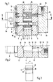
- the housing cover 8 is provided with inlet and outlet bores 20 which are arranged parallel to the axes 14, 16 and offset from the central plane shown in FIG. 1.
- the arrangement is shown in Fig. 2.
- the volume sensor is connected to a connection plate 22 which has inlet and outlet bores 24 which are aligned with the bores 20 and are connected to connection bores 26.
- the further bores are each arranged in the manner of a game to the bores 20, 24 and 26 in the housing half not shown in FIG. 2.
- the measuring wheels 10, 12 are mounted on the fixed axes 14, 16 via bearing elements.
- bearing elements for this purpose, as shown in FIG. 1 above, slide bearings 28 or, as shown in FIG. 1 below, ball bearings 30 can be provided.
- the storage takes place via two spaced-apart bearings.
- the measuring wheels are fitted in the housing 2 in such a way that they circulate on all sides with little play in the measuring chamber.
- flow paths 32 are provided on both housing covers 6 and 8 on both sides of the axis plane in the measuring chamber end walls, between which webs 34 lying in the axis plane are provided, which will be discussed further below .
- the flow paths 32 are connected on the one hand to the inlet side and on the other hand to the outlet side of the volume sensor.
- the housing cover 6 there is a magneto-electrical sensor which lies above the ring gear of one of the two measuring mechanism wheels 10, 12 and which emits an electrical signal for each tooth passing under it.
- a connection box 36 is shown in FIG. 1 as a connection for the sensor.
- the measuring mechanism wheels are provided on both sides in the tooth gaps with a recess 40 which extends radially inward over the tooth gap base (root circle G).
- the width b of this recess essentially corresponds to the tooth gap width in the area of the root circle G of the measuring wheel.
- This depression can extend over the entire height H of the wheel. But it can also be arranged so that it extends only over part of the wheel height H.
- the depression can, as shown in FIG. 3, drop off on both sides starting from the center of the wheel towards the end faces of the wheel.
- the recess can then be produced by bumping or grinding.
- An essential feature of the invention is the configuration of the webs 34 in the axial plane.
- the two edges 42 of the web 34 are formed so that in each case at the center position of the tooth gap of the two measuring wheels in the axis plane A, a broad match in shape between the flanks 41 of the recess 40 of the tooth gap base and the adjoining them Flanks 39 of two adjacent teeth up to the pitch circle T on the one hand and the bilateral edges 42 of the web 34 on the other hand is given, as is illustrated in FIG. 4 for the measuring wheel 10.
- the congruent figuration is to be carried out in such a way that there is a slight positive overlap of the ridge edges by the flanks of the depression and the adjacent teeth 42 with an exact central position of the tooth of the other wheel engaging therebetween, i.e. the width of the tooth gap in this area is slightly smaller than the web width.
- This overlap should be of the order of magnitude of the play with which the gear wheel with its end faces and its circumference is fitted into the measuring mechanism housing. This is illustrated in Fig. 4 by the small distance between the edges shown in dashed lines.
- edges are arranged and the overlap is dimensioned such that there is still an open gap up to about 1 ° before reaching the central position, which in the embodiment described extends from the bottom of the depression to the pitch circle, so over the greatest possible length. Liquid can then flow out until shortly before reaching the middle position.
- the measuring wheels in volume sensors of the present type are designed to achieve high resolution with small teeth and, provided that the design is as small as possible, run at very high speeds, which lead to the disturbing noises in the medium frequency range in the known sensors. For example, a tooth passage through the gap of the counter wheel in less than 1 ms is common.
- the depressions 46 are formed here by means of a protuberance cutter during the production of the toothing.
- the recess extends over the entire wheel width.
- the edges 48 of the web 50 are in turn designed such that, in each case at the above-defined central position of the teeth of the two measuring wheels, there is an extensive congruence between the flanks 49 of the recess 46 of the tooth space base and the opposite flanks 51 of the teeth 53 to to the pitch circle on the one hand and the edges 48 of the web 50 on the other hand is given with a small positive overlap of the web edges by the teeth 53 of the measuring wheel 12.
- the fixed axle bolts 14, 16 are passed through the two housing covers and provided with abutments on the outside.
- the axle bolts 14, 16 are provided on one side with a head 17 which rests on a shoulder in a recess in the lid surface.
- the other end of the axle bolts is provided with a thread 15 onto which a nut 15 'can be screwed. Due to the abutment formed in this way, the two housing covers are additionally braced in the area of the gearwheels and thus the pressurized interior, so that even at high pressures, which can exceed 400 bar in the hydraulics, no change in the end play of the measuring mechanism wheels occurs.
- the upper axle pin 14 is shown with an axial bore 52 which opens into a transverse bore 54 which lies between the two bearing elements 28.
- a flushing liquid can be introduced between the bearing elements 28 via a connection 56 and an adjoining bore 58 in the connection plate 22. This is useful, for example, if a volume sensor is to be shut down for a long time.
- the rinsing liquid can also be used to clean the gaps between the measuring wheels and the housing.
Landscapes
- Physics & Mathematics (AREA)
- Fluid Mechanics (AREA)
- General Physics & Mathematics (AREA)
- Measuring Volume Flow (AREA)
Applications Claiming Priority (2)
| Application Number | Priority Date | Filing Date | Title |
|---|---|---|---|
| DE4040409 | 1990-12-18 | ||
| DE4040409A DE4040409C1 (enExample) | 1990-12-18 | 1990-12-18 |
Publications (3)
| Publication Number | Publication Date |
|---|---|
| EP0491246A2 EP0491246A2 (de) | 1992-06-24 |
| EP0491246A3 EP0491246A3 (en) | 1993-09-22 |
| EP0491246B1 true EP0491246B1 (de) | 1995-04-05 |
Family
ID=6420602
Family Applications (1)
| Application Number | Title | Priority Date | Filing Date |
|---|---|---|---|
| EP91120938A Expired - Lifetime EP0491246B1 (de) | 1990-12-18 | 1991-12-06 | Volumensensor für Flüssigkeiten |
Country Status (4)
| Country | Link |
|---|---|
| US (1) | US5559288A (enExample) |
| EP (1) | EP0491246B1 (enExample) |
| JP (1) | JP3126454B2 (enExample) |
| DE (2) | DE9017839U1 (enExample) |
Families Citing this family (11)
| Publication number | Priority date | Publication date | Assignee | Title |
|---|---|---|---|---|
| DE9402184U1 (de) * | 1994-02-10 | 1994-04-14 | Kracht GmbH, 58791 Werdohl | Meßwerk für einen Volumenzähler |
| DE9412912U1 (de) * | 1994-08-10 | 1994-10-06 | KEM Küppers Elektromechanik GmbH, 85757 Karlsfeld | Volumenzähler, dessen Meßwerk aus zwei oder mehreren axial angeströmten Spindeln besteht |
| DK174370B1 (da) | 1995-10-30 | 2003-01-13 | Salzkotten Tankanlagen | Flowmåler |
| GB9702836D0 (en) * | 1997-02-12 | 1997-04-02 | Apv Uk Plc | Rotor for use in a rotary pump |
| US5992230A (en) * | 1997-11-15 | 1999-11-30 | Hoffer Flow Controls, Inc. | Dual rotor flow meter |
| DE102004027387A1 (de) | 2004-06-04 | 2006-01-05 | Vse Volumentechnik Gmbh | Durchflussmengenfühler und Verfahren zur Messung des Volumens und/oder der Durchflussgeschwindigkeit eines Mediums mit einem Durchflussmengenfühler |
| DE202004010954U1 (de) * | 2004-07-13 | 2005-08-25 | Digmesa Ag | Sensorträger für einen Durchflussmesser |
| PL1994375T3 (pl) | 2006-03-11 | 2016-08-31 | Kracht Gmbh | Przepływomierz objętościowy z czujnikiem |
| AT508805B1 (de) * | 2009-10-09 | 2011-06-15 | Kral Ag | Durchflussmesseinrichtung |
| JP7586630B2 (ja) | 2016-04-04 | 2024-11-19 | ノードソン コーポレーション | 液体接着剤の流れを監視するシステム及び方法 |
| DE102017106838A1 (de) * | 2017-03-30 | 2018-10-04 | Miele & Cie. Kg | Ovalrad-Durchflussmesser, Verfahren zum Herstellen eines Ovalrad-Durchflussmessers, Verfahren und Vorrichtung zum Messen eines Durchflusses und Dosiersystem |
Citations (2)
| Publication number | Priority date | Publication date | Assignee | Title |
|---|---|---|---|---|
| US1129090A (en) * | 1914-04-08 | 1915-02-23 | American La France Fire Engine Company Inc | Gear-pump. |
| DE2810563A1 (de) * | 1978-03-10 | 1979-09-13 | Theodorus Henricus Dipl Korse | Zahnradmaschine (pumpe oder motor) |
Family Cites Families (16)
| Publication number | Priority date | Publication date | Assignee | Title |
|---|---|---|---|---|
| DE305733C (enExample) * | ||||
| DE366152C (de) * | 1922-12-30 | Bbc Brown Boveri & Cie | Einrichtung zur Vermeidung der Quetschwirkung bei Zahnrad-OElpumpen | |
| DE393294C (de) * | 1924-04-07 | August Fuellgrabe | Prismendoppelfernrohr | |
| US2354992A (en) * | 1941-11-11 | 1944-08-01 | Westinghouse Electric & Mfg Co | Gear pump |
| US3274894A (en) * | 1962-01-24 | 1966-09-27 | Bopp & Reuther Gmbh | Hydraulic apparatus |
| US3303792A (en) * | 1964-04-20 | 1967-02-14 | Roper Ind Inc | Gear pump with trapping reliefs |
| DE6609610U (de) * | 1967-11-04 | 1972-07-27 | Kueppers Dipl Ing Karl | Durchflussmessgeber. |
| DE2554466C3 (de) * | 1975-12-04 | 1982-12-02 | Kracht Pumpen- Und Motorenfabrik Gmbh & Co Kg, 5980 Werdohl | Durchflußmengenmeßgerät |
| US4224015A (en) * | 1977-01-19 | 1980-09-23 | Oval Engineering Co., Ltd. | Positive displacement flow meter with helical-toothed rotors |
| DE3147208C2 (de) * | 1980-11-27 | 1984-08-30 | Kracht Pumpen- Und Motorenfabrik Gmbh & Co Kg, 5980 Werdohl | Volumenstromsensor nach Art eines Zahnradmotors |
| EP0053575B1 (de) * | 1980-11-27 | 1984-08-08 | KRACHT Pumpen- und Motorenfabrik GmbH & Co. KG | Volumenstromsensor nach Art eines Zahnradmotors |
| US4400147A (en) * | 1981-03-25 | 1983-08-23 | Binks Manufacturing Company | Flushable rotary gear pump |
| DE3321952C2 (de) * | 1983-06-18 | 1985-08-22 | Bopp & Reuther Gmbh, 6800 Mannheim | Elektromagnetischer Impulsaufnehmer für Durchflußmesser |
| DE3728938A1 (de) * | 1987-08-29 | 1989-03-16 | Kracht Pumpen Motoren | Volumenzaehler |
| US4911010A (en) * | 1988-08-12 | 1990-03-27 | Flowdata, Inc. | Fluid flowmeter |
| EP0393294A1 (de) * | 1989-04-17 | 1990-10-24 | Dopag Ag | Durchflussvolumenzähler |
-
1990
- 1990-12-18 DE DE9017839U patent/DE9017839U1/de not_active Expired - Lifetime
- 1990-12-18 DE DE4040409A patent/DE4040409C1/de not_active Expired - Lifetime
-
1991
- 1991-12-06 EP EP91120938A patent/EP0491246B1/de not_active Expired - Lifetime
- 1991-12-17 JP JP03333346A patent/JP3126454B2/ja not_active Expired - Lifetime
-
1995
- 1995-12-07 US US08/568,739 patent/US5559288A/en not_active Expired - Lifetime
Patent Citations (2)
| Publication number | Priority date | Publication date | Assignee | Title |
|---|---|---|---|---|
| US1129090A (en) * | 1914-04-08 | 1915-02-23 | American La France Fire Engine Company Inc | Gear-pump. |
| DE2810563A1 (de) * | 1978-03-10 | 1979-09-13 | Theodorus Henricus Dipl Korse | Zahnradmaschine (pumpe oder motor) |
Non-Patent Citations (1)
| Title |
|---|
| US-1129090 * |
Also Published As
| Publication number | Publication date |
|---|---|
| EP0491246A3 (en) | 1993-09-22 |
| DE4040409C1 (enExample) | 1992-05-14 |
| US5559288A (en) | 1996-09-24 |
| EP0491246A2 (de) | 1992-06-24 |
| JP3126454B2 (ja) | 2001-01-22 |
| DE9017839U1 (de) | 1992-04-30 |
| JPH04276521A (ja) | 1992-10-01 |
Similar Documents
| Publication | Publication Date | Title |
|---|---|---|
| EP0491246B1 (de) | Volumensensor für Flüssigkeiten | |
| DE60014340T2 (de) | Schraubenrotorbauweise für fluidverdrängungsanlage | |
| EP3015829A1 (de) | Spindeldurchflussmesser | |
| AT400766B (de) | Einrichtung zur volumenmessung strömender medien | |
| EP0053575A1 (de) | Volumenstromsensor nach Art eines Zahnradmotors | |
| EP2696176B1 (de) | Zahnraddurchflussmesser | |
| DE4208869C2 (de) | Volumetrischer Kraftstoff-Durchflußmesser | |
| DE2446416C3 (de) | DurchfluBmesser | |
| DE2224857A1 (de) | Strömungsvolumen-Meßgerät | |
| DE19731173C2 (de) | Ultraschall-Durchflußmengenmesser | |
| DE2756215A1 (de) | Kupplungsvorrichtung zur verbindung des messteils mit dem anzeigeteil von gasmessgeraeten | |
| DE2249952A1 (de) | Zahnradmaschine | |
| AT517818B1 (de) | Zweiseitig anströmbare Vorrichtung zur Messung von Durchflussvorgängen von Fluiden | |
| EP1211489A2 (de) | Drehkolbenzähler | |
| DE2709913A1 (de) | Zahnradmaschine (pumpe oder motor) | |
| DE2701303C3 (de) | Hydraulische Zahnradmaschine | |
| DE9418104U1 (de) | Volumenzähler | |
| DE3249829C2 (en) | Parallel and internal axis rotary piston engine | |
| DE910970C (de) | Zahnradeinspritzpumpe | |
| EP0841483A2 (de) | Zahnradpumpe mit drehbarem Dichtsteg | |
| DE9402184U1 (de) | Meßwerk für einen Volumenzähler | |
| DE2940096A1 (de) | Durchflussmengenmesser | |
| DE19631956A1 (de) | Zahnradpumpe mit einstellbarem Verdrängungsvolumen | |
| DE2146763C3 (de) | Volumenzähler | |
| DE102007011439A1 (de) | Durchflusssensor |
Legal Events
| Date | Code | Title | Description |
|---|---|---|---|
| PUAI | Public reference made under article 153(3) epc to a published international application that has entered the european phase |
Free format text: ORIGINAL CODE: 0009012 |
|
| AK | Designated contracting states |
Kind code of ref document: A2 Designated state(s): CH FR GB IT LI |
|
| 17P | Request for examination filed |
Effective date: 19930506 |
|
| PUAL | Search report despatched |
Free format text: ORIGINAL CODE: 0009013 |
|
| AK | Designated contracting states |
Kind code of ref document: A3 Designated state(s): CH FR GB IT LI |
|
| GBC | Gb: translation of claims filed (gb section 78(7)/1977) | ||
| 17Q | First examination report despatched |
Effective date: 19940329 |
|
| GRAA | (expected) grant |
Free format text: ORIGINAL CODE: 0009210 |
|
| AK | Designated contracting states |
Kind code of ref document: B1 Designated state(s): CH FR GB IT LI |
|
| GBT | Gb: translation of ep patent filed (gb section 77(6)(a)/1977) |
Effective date: 19950331 |
|
| EL | Fr: translation of claims filed | ||
| ET | Fr: translation filed | ||
| EL | Fr: translation of claims filed |
Free format text: BO 95/19: ANNULATION |
|
| ITF | It: translation for a ep patent filed | ||
| PLBE | No opposition filed within time limit |
Free format text: ORIGINAL CODE: 0009261 |
|
| STAA | Information on the status of an ep patent application or granted ep patent |
Free format text: STATUS: NO OPPOSITION FILED WITHIN TIME LIMIT |
|
| 26N | No opposition filed | ||
| REG | Reference to a national code |
Ref country code: GB Ref legal event code: IF02 |
|
| REG | Reference to a national code |
Ref country code: CH Ref legal event code: PFA Owner name: VSE VOLUMENTECHNIK GMBH Free format text: VSE VOLUMENTECHNIK GMBH#HOENNESTRASSE 47#D-58809 NEUENRADE (DE) -TRANSFER TO- VSE VOLUMENTECHNIK GMBH#HOENNESTRASSE 47#D-58809 NEUENRADE (DE) |
|
| PGFP | Annual fee paid to national office [announced via postgrant information from national office to epo] |
Ref country code: FR Payment date: 20080919 Year of fee payment: 18 |
|
| PGFP | Annual fee paid to national office [announced via postgrant information from national office to epo] |
Ref country code: CH Payment date: 20081222 Year of fee payment: 18 |
|
| PGFP | Annual fee paid to national office [announced via postgrant information from national office to epo] |
Ref country code: GB Payment date: 20081001 Year of fee payment: 18 |
|
| PGFP | Annual fee paid to national office [announced via postgrant information from national office to epo] |
Ref country code: IT Payment date: 20081230 Year of fee payment: 18 |
|
| REG | Reference to a national code |
Ref country code: CH Ref legal event code: PL |
|
| GBPC | Gb: european patent ceased through non-payment of renewal fee |
Effective date: 20091206 |
|
| REG | Reference to a national code |
Ref country code: FR Ref legal event code: ST Effective date: 20100831 |
|
| PG25 | Lapsed in a contracting state [announced via postgrant information from national office to epo] |
Ref country code: LI Free format text: LAPSE BECAUSE OF NON-PAYMENT OF DUE FEES Effective date: 20091231 Ref country code: CH Free format text: LAPSE BECAUSE OF NON-PAYMENT OF DUE FEES Effective date: 20091231 Ref country code: FR Free format text: LAPSE BECAUSE OF NON-PAYMENT OF DUE FEES Effective date: 20091231 |
|
| PG25 | Lapsed in a contracting state [announced via postgrant information from national office to epo] |
Ref country code: GB Free format text: LAPSE BECAUSE OF NON-PAYMENT OF DUE FEES Effective date: 20091206 |
|
| PG25 | Lapsed in a contracting state [announced via postgrant information from national office to epo] |
Ref country code: IT Free format text: LAPSE BECAUSE OF NON-PAYMENT OF DUE FEES Effective date: 20091206 |