EP0490254A1 - Zerlegbare Halle - Google Patents
Zerlegbare Halle Download PDFInfo
- Publication number
- EP0490254A1 EP0490254A1 EP91120836A EP91120836A EP0490254A1 EP 0490254 A1 EP0490254 A1 EP 0490254A1 EP 91120836 A EP91120836 A EP 91120836A EP 91120836 A EP91120836 A EP 91120836A EP 0490254 A1 EP0490254 A1 EP 0490254A1
- Authority
- EP
- European Patent Office
- Prior art keywords
- foundation plate
- roof
- hall according
- detachable
- pipe
- Prior art date
- Legal status (The legal status is an assumption and is not a legal conclusion. Google has not performed a legal analysis and makes no representation as to the accuracy of the status listed.)
- Withdrawn
Links
- 238000003197 gene knockdown Methods 0.000 title abstract 2
- 239000011521 glass Substances 0.000 claims abstract description 5
- 238000007789 sealing Methods 0.000 claims description 3
- 238000004873 anchoring Methods 0.000 claims description 2
- 239000004566 building material Substances 0.000 claims description 2
- 230000002787 reinforcement Effects 0.000 claims description 2
- 238000000576 coating method Methods 0.000 claims 1
- 239000002352 surface water Substances 0.000 claims 1
- 238000010276 construction Methods 0.000 abstract description 9
- 230000007797 corrosion Effects 0.000 abstract description 4
- 238000005260 corrosion Methods 0.000 abstract description 4
- 238000004519 manufacturing process Methods 0.000 description 4
- 239000000463 material Substances 0.000 description 3
- 230000015572 biosynthetic process Effects 0.000 description 2
- XLYOFNOQVPJJNP-UHFFFAOYSA-N water Substances O XLYOFNOQVPJJNP-UHFFFAOYSA-N 0.000 description 2
- 230000006978 adaptation Effects 0.000 description 1
- XAGFODPZIPBFFR-UHFFFAOYSA-N aluminium Chemical compound [Al] XAGFODPZIPBFFR-UHFFFAOYSA-N 0.000 description 1
- 229910052782 aluminium Inorganic materials 0.000 description 1
- 238000005452 bending Methods 0.000 description 1
- 239000011449 brick Substances 0.000 description 1
- 239000000919 ceramic Substances 0.000 description 1
- 238000009408 flooring Methods 0.000 description 1
- 238000002372 labelling Methods 0.000 description 1
- 239000004579 marble Substances 0.000 description 1
- 239000004033 plastic Substances 0.000 description 1
- 238000002360 preparation method Methods 0.000 description 1
- 239000005060 rubber Substances 0.000 description 1
- 239000010865 sewage Substances 0.000 description 1
- 229910001220 stainless steel Inorganic materials 0.000 description 1
- 239000010935 stainless steel Substances 0.000 description 1
- 230000003068 static effect Effects 0.000 description 1
- 239000004753 textile Substances 0.000 description 1
- 239000002351 wastewater Substances 0.000 description 1
Images

Classifications
-
- E—FIXED CONSTRUCTIONS
- E04—BUILDING
- E04H—BUILDINGS OR LIKE STRUCTURES FOR PARTICULAR PURPOSES; SWIMMING OR SPLASH BATHS OR POOLS; MASTS; FENCING; TENTS OR CANOPIES, IN GENERAL
- E04H1/00—Buildings or groups of buildings for dwelling or office purposes; General layout, e.g. modular co-ordination or staggered storeys
- E04H1/12—Small buildings or other erections for limited occupation, erected in the open air or arranged in buildings, e.g. kiosks, waiting shelters for bus stops or for filling stations, roofs for railway platforms, watchmen's huts or dressing cubicles
- E04H1/1205—Small buildings erected in the open air
- E04H1/1211—Waiting shelters for bus stops
Definitions
- the invention relates to a demountable hall, consisting of pipe supports with devices for the lateral reception or attachment of plate-shaped components between the adjacent supports, such as Glass panes, building material panels or the like, as well as a roof surface arranged between the upper ends of the supports and a foundation plate serving to fasten the supports.
- Detachable halls of this type are preferably used as waiting halls, in particular on bus and train lines, and as pavilions and the like, which are made in a popular manner from aluminum or stainless steel pipe supports with glass and advertising surfaces arranged in between.
- the corner formation of the profiles comprising the roof surfaces is technically very complex and must also be designed to be extremely stable, on the one hand to obtain a stable torsion-resistant roof construction and on the other hand to ensure a relatively firm connection on or laterally on the outer surfaces of the tubular supports.
- Another disadvantage is the assembly of the halls on heavily frequented traffic routes, streets and squares, the traffic being unnecessarily long hindered by the necessary demarcation of the construction site and the extensive assembly time.
- DE-GM 79 15 954 discloses a generic, separable room cell which can be assembled into large-scale units and in which a floor element is connected to a ceiling element by means of corner columns.
- the connection of the pillar-forming corner pillars in this known room cell consist of plug-in elements which are not suitable for open and free-standing halls because of the lack of a positive connection.
- the corner pillars, which are made with a lot of material, cannot be used for the bending forces that occur, because the cross-section of the plug connections is smaller than the cross-section of the supports.
- the strength of such a room cell is only achieved by inserting the wall elements.
- This known construction is not suitable for the production of open or semi-open halls.
- the invention is therefore based on the object of creating a demountable hall of the type described above, with which a very high static strength is achieved with a low cost of materials.
- a hall equipped with these features can be produced very quickly and precisely regardless of the weather in workshops and can be set up completely and ready for use in a short time at the intended places without significantly obstructing traffic. Furthermore, such halls can be made available in a few minutes if there is an unexpectedly high demand and can be moved to other locations at short notice without additional assembly work. These halls are optimally protected against corrosion and equipped with all connection devices for the supply and disposal lines, such as power and telephone cables, as well as waste water pipes. The interchangeability when individual components of such a hall are damaged is incomparably simple and quick to carry out.
- the foundation slabs that can be equipped with functional flooring, such as wear-resistant brick up to the demanding mosaic floor, can also be selected depending on the type of stand from an aesthetic point of view. Furthermore, because of the workshop production, the floor covering can also be expediently provided with permanent advertising or informational labeling, which cannot be produced outside of workshops or can only be produced with great difficulty.
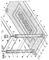
- Fig. 1 the dismantled hall is shown with the required individual parts, in which the easy assembly of the individual parts can be seen.
- the pipe supports 1 consist of extruded pipes which are cut to the desired length, untreated and without connecting elements with the full cross-sectional area 19 in the direction of arrow 20 with a close fit into the guide pipes 2 up to the lower stop plate 10.
- the pipe supports 1 are thus already aligned parallel to one another and in height in the same horizontal plane. It is only necessary to lock the pipe supports 1 by screwing in the securing bolts 4 through the bolt channels 14 provided for this purpose in the side edges 13 of the foundation plate 3.
- the arrangement of the support-receiving guide tubes 2 is shown in more detail in a section 18 of the foundation plate 3.
- the guide tube 2 is provided on the outer wall with welded elevations for the reinforcement in the concrete, for example with welded head bolts 24.
- a secure, movement-free fit of the guide tubes 2 in the foundation plate 3 is achieved even under high loads.
- the supports 1 are kept correctly aligned at right angles to the surface 16 of the foundation plate 3 and are also adjusted in height in one plane by the welded-on stop plates 10.
- a quick assembly is also ensured because no connecting elements are required at the ends of the supports and the entire cross-sectional area 19 of the cut pipe supports 1 is received unchanged in the guide tube 2.
- the stop plate 10 is advantageously provided with an opening in the central area, for example with a bore 25, in order to ensure the drainage of the rainwater.
- a standardized connection sleeve 36 can be arranged in the foundation plate 3 for connection to the sewage disposal for this purpose.
- Such a connecting sleeve 36 can advantageously be firmly cast in the concrete during the manufacture of the foundation plate 3.
- the bore 25 and the connecting sleeve 36 can also be used, for example in another, adjacent pipe support 1, as a supply line for supply lines, for example for power cables, telephone connecting lines or the like.
- the welded-on stop plate 10 can be made larger than the cross-sectional area 19 of the guide tube 2, as a result of which a larger anchoring surface in the foundation plate 3 is achieved in connection with the welded-on head bolts 24.
- the guide tubes 2 are expediently used to avoid corrosion below the upper level of the surface 16, so that the upper edge 26 of the guide tubes 2 is still covered by the upper layer of the foundation plate 3 when the surface 16 is chamfered to form a putty joint 17 is.
- the chamfered putty joint 17 can correspond in width, for example, to the existing tile joints of a tiled surface 16 of the foundation plate 3, so that on the support 1 used, a clean connection to the finished coated surface 16 can also be made with a suitable joint putty or the like with little work achieved and thus a completely watertight closure is achieved.
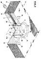
- the tube support 1 After inserting the tube support 1 (not shown in FIG. 2) into the guide tube 2, the tube support 1 is firmly anchored in the foundation plate 3 by means of a securing bolt 4.
- the securing bolt 4 is pushed through a bolt channel 14 accessible from the side edge 13 of the foundation plate 3 through the bores 12 in the guide tube 2 and in the tube supports 1 and, for example, by means of thread 28 in a bolt lock 15, for example in the form of a welded-on threaded nut 29, screwed tight.
- the bolt channel 14 is expediently closed in a moisture-proof manner with a sealing plug 30 in the direction of the arrow shown.
- the roof covering of the demountable hall is trough-shaped, made in one piece. At least in a roof corner 6 there is a breakthrough serving as a drain 23 through which the rainwater is introduced from the roof surface 7 into the interior of a pipe support 1 and - as described - is supplied to the sewer in the roof surface 7.
- this drain 23 can be equipped with a drain grommet 33, whereby not only the roof corner 6 is stabilized, but also the rainwater can be introduced in a targeted manner, for example into the inner pipe 34 of a double pipe support.
- Such a roof corner 6 is placed in the sector-like recesses 5 of the cross-sectional area 19 of the pipe supports 1 already installed in the foundation 3 and secured by means of screwed-in connecting elements of a known type which are guided through the bores 35.
- the open cross section at the upper end of the pipe supports 1 is closed by means of an end cap (8) which can be plugged onto the pipe profile 1.
- an end cap (8) which can be plugged onto the pipe profile 1.
Landscapes
- Engineering & Computer Science (AREA)
- Architecture (AREA)
- Civil Engineering (AREA)
- Structural Engineering (AREA)
- Joining Of Building Structures In Genera (AREA)
Applications Claiming Priority (2)
| Application Number | Priority Date | Filing Date | Title |
|---|---|---|---|
| DE4039424 | 1990-12-11 | ||
| DE19904039424 DE4039424C1 (enExample) | 1990-12-11 | 1990-12-11 |
Publications (1)
| Publication Number | Publication Date |
|---|---|
| EP0490254A1 true EP0490254A1 (de) | 1992-06-17 |
Family
ID=6420006
Family Applications (1)
| Application Number | Title | Priority Date | Filing Date |
|---|---|---|---|
| EP91120836A Withdrawn EP0490254A1 (de) | 1990-12-11 | 1991-12-04 | Zerlegbare Halle |
Country Status (2)
| Country | Link |
|---|---|
| EP (1) | EP0490254A1 (enExample) |
| DE (1) | DE4039424C1 (enExample) |
Families Citing this family (1)
| Publication number | Priority date | Publication date | Assignee | Title |
|---|---|---|---|---|
| DE102006014809B4 (de) * | 2006-03-29 | 2009-04-16 | Hodes Bouwsystemen B.V. | Bauwerk aus Fertigteilen |
Citations (1)
| Publication number | Priority date | Publication date | Assignee | Title |
|---|---|---|---|---|
| FR2267435A1 (en) * | 1974-04-12 | 1975-11-07 | Lemettre Gerard | Modular steel-framed building construction - has welded crowns joining posts, floor base and foundation |
Family Cites Families (3)
| Publication number | Priority date | Publication date | Assignee | Title |
|---|---|---|---|---|
| DE7716535U1 (de) * | 1977-05-25 | 1977-09-01 | Betonwerk Hof Raithel Gmbh, 8670 Hof | Fertigbauwerk |
| DE7915954U1 (de) * | 1979-06-01 | 1979-11-29 | B & W Transportsysteme Gmbh, 2400 Luebeck | Zu grossraumeinheiten zusammenstellbare, zerlegbare raumzelle |
| FR2542354B2 (fr) * | 1983-03-09 | 1987-07-31 | Bourlier Claude | Abri individuel blinde transportable et demontable |
-
1990
- 1990-12-11 DE DE19904039424 patent/DE4039424C1/de not_active Expired - Lifetime
-
1991
- 1991-12-04 EP EP91120836A patent/EP0490254A1/de not_active Withdrawn
Patent Citations (1)
| Publication number | Priority date | Publication date | Assignee | Title |
|---|---|---|---|---|
| FR2267435A1 (en) * | 1974-04-12 | 1975-11-07 | Lemettre Gerard | Modular steel-framed building construction - has welded crowns joining posts, floor base and foundation |
Also Published As
| Publication number | Publication date |
|---|---|
| DE4039424C1 (enExample) | 1992-02-06 |
Similar Documents
| Publication | Publication Date | Title |
|---|---|---|
| DE102015001891B4 (de) | Randeinfassung für Balkon- und Terrassenböden | |
| DE3824387C2 (enExample) | ||
| DE602004004692T2 (de) | Balkon oder ähnliches | |
| CH702922B1 (de) | Abschlussbauelement für einen Balkon oder eine Fassade eines Gebäudes. | |
| DE29920081U1 (de) | Balkon aus Metall | |
| DE29716050U1 (de) | Balkon zur Anordnung vor der Fassade eines Bauwerkes | |
| DE4039424C1 (enExample) | ||
| DE19920032A1 (de) | Herstellungs- und Montagesystem für Fertigteile von Gebäuden | |
| EP0227937A1 (de) | Balkon zum nachträglichen Anbringen an ein Gebäude | |
| DE29802829U1 (de) | Überlaufrinne für Schwimmbecken | |
| DE29507126U1 (de) | Nachträglich anbaubarer Balkon oder Wintergarten | |
| EP0631022B1 (de) | Raumkörper zur Errichtung von Bauwerken und Verfahren zu seiner Herstellung | |
| EP1606466B1 (de) | Verfahren zur herstellung eines balkons oder einer terrasse, betonfertigteil und betonfertigteilsystem | |
| EP1736605B1 (de) | Balkonzarge, Balkon sowie Verfahren zum Herstellen eines Fertigteilbalkons | |
| DE9017614U1 (de) | Zerlegbare Halle | |
| DE9308576U1 (de) | Bausatz für einen Balkon | |
| DE29923649U1 (de) | Fertighaussystem | |
| AT524849A4 (de) | Montagesystem für Geländer und Absturzsicherungen | |
| DE20305659U1 (de) | Ständerbauwerk, insbesondere aufgeständerter Vorsatzbalkon | |
| DE29620796U1 (de) | Wandstützenbefestigung | |
| DE19618003C2 (de) | Vorsatzbalkon | |
| DE10017890B4 (de) | Entwässerungssystem für Balkone | |
| DE19650105A1 (de) | Tragkonstruktion | |
| DE29608152U1 (de) | Vorsatzbalkon | |
| EP4464851A2 (de) | Gebäude |
Legal Events
| Date | Code | Title | Description |
|---|---|---|---|
| PUAI | Public reference made under article 153(3) epc to a published international application that has entered the european phase |
Free format text: ORIGINAL CODE: 0009012 |
|
| 17P | Request for examination filed |
Effective date: 19911230 |
|
| AK | Designated contracting states |
Kind code of ref document: A1 Designated state(s): AT BE CH DE DK ES FR GB GR IT LI LU NL SE |
|
| 17Q | First examination report despatched |
Effective date: 19921217 |
|
| RAP1 | Party data changed (applicant data changed or rights of an application transferred) |
Owner name: PTS PATENTS AND TRADEMARK RIGHTS SERVICES NV |
|
| STAA | Information on the status of an ep patent application or granted ep patent |
Free format text: STATUS: THE APPLICATION IS DEEMED TO BE WITHDRAWN |
|
| 18D | Application deemed to be withdrawn |
Effective date: 19931020 |