EP0489343A2 - Dispositif de commande ou de régulation d'appareils alimentés par accumulateurs - Google Patents
Dispositif de commande ou de régulation d'appareils alimentés par accumulateurs Download PDFInfo
- Publication number
- EP0489343A2 EP0489343A2 EP91120215A EP91120215A EP0489343A2 EP 0489343 A2 EP0489343 A2 EP 0489343A2 EP 91120215 A EP91120215 A EP 91120215A EP 91120215 A EP91120215 A EP 91120215A EP 0489343 A2 EP0489343 A2 EP 0489343A2
- Authority
- EP
- European Patent Office
- Prior art keywords
- housing
- contact
- switch
- handle
- circuit
- Prior art date
- Legal status (The legal status is an assumption and is not a legal conclusion. Google has not performed a legal analysis and makes no representation as to the accuracy of the status listed.)
- Withdrawn
Links
Images


Classifications
-
- H—ELECTRICITY
- H02—GENERATION; CONVERSION OR DISTRIBUTION OF ELECTRIC POWER
- H02M—APPARATUS FOR CONVERSION BETWEEN AC AND AC, BETWEEN AC AND DC, OR BETWEEN DC AND DC, AND FOR USE WITH MAINS OR SIMILAR POWER SUPPLY SYSTEMS; CONVERSION OF DC OR AC INPUT POWER INTO SURGE OUTPUT POWER; CONTROL OR REGULATION THEREOF
- H02M1/00—Details of apparatus for conversion
- H02M1/08—Circuits specially adapted for the generation of control voltages for semiconductor devices incorporated in static converters
-
- H—ELECTRICITY
- H02—GENERATION; CONVERSION OR DISTRIBUTION OF ELECTRIC POWER
- H02P—CONTROL OR REGULATION OF ELECTRIC MOTORS, ELECTRIC GENERATORS OR DYNAMO-ELECTRIC CONVERTERS; CONTROLLING TRANSFORMERS, REACTORS OR CHOKE COILS
- H02P7/00—Arrangements for regulating or controlling the speed or torque of electric DC motors
- H02P7/06—Arrangements for regulating or controlling the speed or torque of electric DC motors for regulating or controlling an individual dc dynamo-electric motor by varying field or armature current
- H02P7/18—Arrangements for regulating or controlling the speed or torque of electric DC motors for regulating or controlling an individual dc dynamo-electric motor by varying field or armature current by master control with auxiliary power
- H02P7/24—Arrangements for regulating or controlling the speed or torque of electric DC motors for regulating or controlling an individual dc dynamo-electric motor by varying field or armature current by master control with auxiliary power using discharge tubes or semiconductor devices
- H02P7/28—Arrangements for regulating or controlling the speed or torque of electric DC motors for regulating or controlling an individual dc dynamo-electric motor by varying field or armature current by master control with auxiliary power using discharge tubes or semiconductor devices using semiconductor devices
-
- H—ELECTRICITY
- H01—ELECTRIC ELEMENTS
- H01H—ELECTRIC SWITCHES; RELAYS; SELECTORS; EMERGENCY PROTECTIVE DEVICES
- H01H9/00—Details of switching devices, not covered by groups H01H1/00 - H01H7/00
- H01H9/02—Bases, casings, or covers
- H01H9/06—Casing of switch constituted by a handle serving a purpose other than the actuation of the switch, e.g. by the handle of a vacuum cleaner
- H01H9/061—Casing of switch constituted by a handle serving a purpose other than the actuation of the switch, e.g. by the handle of a vacuum cleaner enclosing a continuously variable impedance
-
- H—ELECTRICITY
- H02—GENERATION; CONVERSION OR DISTRIBUTION OF ELECTRIC POWER
- H02J—CIRCUIT ARRANGEMENTS OR SYSTEMS FOR SUPPLYING OR DISTRIBUTING ELECTRIC POWER; SYSTEMS FOR STORING ELECTRIC ENERGY
- H02J7/00—Circuit arrangements for charging or depolarising batteries or for supplying loads from batteries
- H02J7/02—Circuit arrangements for charging or depolarising batteries or for supplying loads from batteries for charging batteries from ac mains by converters
-
- H—ELECTRICITY
- H02—GENERATION; CONVERSION OR DISTRIBUTION OF ELECTRIC POWER
- H02P—CONTROL OR REGULATION OF ELECTRIC MOTORS, ELECTRIC GENERATORS OR DYNAMO-ELECTRIC CONVERTERS; CONTROLLING TRANSFORMERS, REACTORS OR CHOKE COILS
- H02P27/00—Arrangements or methods for the control of AC motors characterised by the kind of supply voltage
- H02P27/04—Arrangements or methods for the control of AC motors characterised by the kind of supply voltage using variable-frequency supply voltage, e.g. inverter or converter supply voltage
- H02P27/06—Arrangements or methods for the control of AC motors characterised by the kind of supply voltage using variable-frequency supply voltage, e.g. inverter or converter supply voltage using dc to ac converters or inverters
-
- H—ELECTRICITY
- H05—ELECTRIC TECHNIQUES NOT OTHERWISE PROVIDED FOR
- H05K—PRINTED CIRCUITS; CASINGS OR CONSTRUCTIONAL DETAILS OF ELECTRIC APPARATUS; MANUFACTURE OF ASSEMBLAGES OF ELECTRICAL COMPONENTS
- H05K7/00—Constructional details common to different types of electric apparatus
- H05K7/20—Modifications to facilitate cooling, ventilating, or heating
- H05K7/2089—Modifications to facilitate cooling, ventilating, or heating for power electronics, e.g. for inverters for controlling motor
- H05K7/209—Heat transfer by conduction from internal heat source to heat radiating structure
-
- H—ELECTRICITY
- H01—ELECTRIC ELEMENTS
- H01H—ELECTRIC SWITCHES; RELAYS; SELECTORS; EMERGENCY PROTECTIVE DEVICES
- H01H11/00—Apparatus or processes specially adapted for the manufacture of electric switches
- H01H11/0006—Apparatus or processes specially adapted for the manufacture of electric switches for converting electric switches
- H01H11/0031—Apparatus or processes specially adapted for the manufacture of electric switches for converting electric switches for allowing different types or orientation of connections to contacts
-
- H—ELECTRICITY
- H01—ELECTRIC ELEMENTS
- H01H—ELECTRIC SWITCHES; RELAYS; SELECTORS; EMERGENCY PROTECTIVE DEVICES
- H01H9/00—Details of switching devices, not covered by groups H01H1/00 - H01H7/00
- H01H9/02—Bases, casings, or covers
- H01H9/06—Casing of switch constituted by a handle serving a purpose other than the actuation of the switch, e.g. by the handle of a vacuum cleaner
- H01H2009/065—Battery operated hand tools in which the battery and the switch are directly connected
-
- H—ELECTRICITY
- H01—ELECTRIC ELEMENTS
- H01H—ELECTRIC SWITCHES; RELAYS; SELECTORS; EMERGENCY PROTECTIVE DEVICES
- H01H2300/00—Orthogonal indexing scheme relating to electric switches, relays, selectors or emergency protective devices covered by H01H
- H01H2300/002—Application electric motor braking, e.g. pole reversal of rotor, shorting motor coils, also for field discharge
-
- H—ELECTRICITY
- H01—ELECTRIC ELEMENTS
- H01H—ELECTRIC SWITCHES; RELAYS; SELECTORS; EMERGENCY PROTECTIVE DEVICES
- H01H9/00—Details of switching devices, not covered by groups H01H1/00 - H01H7/00
- H01H9/02—Bases, casings, or covers
- H01H9/06—Casing of switch constituted by a handle serving a purpose other than the actuation of the switch, e.g. by the handle of a vacuum cleaner
- H01H9/063—Casing of switch constituted by a handle serving a purpose other than the actuation of the switch, e.g. by the handle of a vacuum cleaner enclosing a reversing switch
-
- H—ELECTRICITY
- H01—ELECTRIC ELEMENTS
- H01H—ELECTRIC SWITCHES; RELAYS; SELECTORS; EMERGENCY PROTECTIVE DEVICES
- H01H9/00—Details of switching devices, not covered by groups H01H1/00 - H01H7/00
- H01H9/52—Cooling of switch parts
Definitions
- the invention is based on a device according to the preamble of claim 1.
- Devices or electronic switches which are used to control electrical devices supplied by rechargeable batteries or batteries, especially the connection of electric motors to batteries that supply them with current, are known in a large number of embodiments, specifically in connection with handheld electrical devices such as drills, cordless screwdrivers or the like .
- handheld electrical devices such as drills, cordless screwdrivers or the like .
- control of the motor driving the electric handheld device from a battery supplied current flows through a power semiconductor, the conductivity of which is ultimately influenced by the position of a pusher handle so that power control of the operation of the electric motor is possible.
- Corresponding battery switches such as those from companies such as CAPAX and. The like. are manufactured and sold, are usually designed so that at least the power transistor as a single module together with a required heat sink must be arranged externally to the electronic switch housing, at a point within the device whose motor is to be controlled or regulated. In this way, the power semiconductor can be cooled sufficiently, for example by attaching it to a housing wall or the like, that damage during controlled operation is largely excluded.
- the known structure of the CAPAX electronic switch is also such that an actual, closed housing is not provided; a housing is formed from three clearly distinguishable housing part components by plugging them together, in addition to the individual component of the power transistor. So there is a separate right / left switch snapped onto the known housing, which is itself connected to the housing via two line connections running along the outside of the housing, in addition to three additional leads that are led from the housing to the individual component of the power transistor have to.
- All internal or external electrical connections i.e. to the battery or to the motor connections, are designed as direct connections, which make it necessary to insert tinned wire ends into housing openings, in which they are then locked by locking tongues.
- the invention relates generally to such an electronic switch for controlling motors, for example in handheld electrical devices, which are supplied from rechargeable batteries or batteries.
- this is only a preferred exemplary embodiment of the invention and can also be used with other battery-operated devices and systems.
- the description of the invention and also in the foregoing of the known prior art relates only to a special field of application in which the subject matter of the invention can also be used with particular advantage.
- the invention is based on the object, in a supply circuit for consumers supplied by battery or battery operation, especially motor drives, to accommodate the load, that is to say the motor-controlling power semiconductors, on the one hand, within a closed, narrowly limited switch housing and, on the other hand, to ensure that a sufficient level is nevertheless achieved Heat dissipation is secured.
- the device according to the invention solves this problem with the characterizing features of the main claim and has the advantage that it is possible to arrange the power semiconductors, which usually have a comparatively high power loss, on a circuit or printed circuit board, which is preferably formed by a ceramic substrate, without local or general signs of overheating and may also destroy at least the power semiconductor.
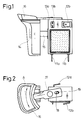
- FIG. 1 shows that all of the components required for the controlled (or possibly also regulated) power supply to cordless devices, for example for their speed control, are arranged in a uniform, closed housing, specifically and specifically the electronic high-power semiconductor switch as well the most frequently provided option for switching the driven battery device from right to left.
- the electronic switch has only and preferably four main contact connections leading to the outside, namely the two connections 11a and 11b to be connected to the rechargeable battery, which in the exemplary embodiment shown look out of the device from below, as well as via two further contact connections 12a, 12b which extend laterally at the top and which form the motor connection terminals and originate from the area of the right-left switch.
- connection contacts are plug-in connections which have the form of metallic contact tongues penetrating the device wall, onto which, as is known, for example, from automotive engineering, further mating contact terminals can be plugged on.
- the electronic switch housing essentially dust-tight; the feedthrough openings in the housing can be tolerated close-fitting, or it is alternatively also possible for the respective ones to face the outside overmolding leading contact tracks from the housing material.
- a few more additional connections can be routed to the outside, for example the two narrower contact plug connections for light-emitting diode displays (one light-emitting diode color for displaying battery undervoltage - another light-emitting diode color for overtemperature indication, which is also an automatic one Down regulation of the power output corresponds, this will be discussed further below).
- the starter or hand lever handle 14 which sits on a handle axis 15 guided in the housing, is the right-left switch lever 16 which, as is known per se and can be seen from FIG. 2, about a fixed axis 17 in The double direction of arrow A is pivotally mounted and receives a switching pin 19 in an elongated hole 18, which actuates a rocker switch 20 (FIG. 9) through a housing opening.
- a mechanical connection is provided between the handle 14 and the right-left switch lever 16, which is designed so that the right-left switch lever 16 can only be actuated when the handle 14 is in the off position.
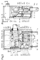
- the hybrid module 22 with casting frame 23 is adjoined by a switch area 24 which continues upwards into the area of the pusher guide 25.
- a switch area 24 which continues upwards into the area of the pusher guide 25.
- the area 26 of the right-left switch which extends across the entire surface but is arranged within the uniform housing, of which the logically mentioned ones mentioned earlier Engine connection tabs 12a, 12b go out.
- a potentiometer area 27 which has not been mentioned so far and is indispensable for the accelerator function of the electronic switch, is still located on the ceramic substrate 22a of the hybrid module 22 in the plane of FIG arranged and contacted by a fork-shaped grinder 28 guided in a bearing in the handle axis 15.
- an IC for example in the form of a MOS-FET
- a sufficiently dimensioned cooling plate or cooling body 29 is arranged on the other side of the ceramic substrate 22a, as shown in FIG. 4, namely, for example, with a thermally conductive adhesive glued to the back of the ceramic substrate.
- This heat sink 29 can be a thicker copper plate with the dimensions of the ceramic substrate or the hybrid component 22 formed by it, the heat sink 29 projecting outwards through a bottom opening 30 in the pot-shaped housing part 21 of the electronic switch housing.
- the IC comprising the semiconductor switch (MOS-FET) is designed such that it regulates under load even when predetermined temperatures are exceeded, that is to say throttles its power output so far, how this is relevant to its performance data.
- MOS-FET semiconductor switch
- the IC circuit is bridged by a bypass switch, while, on the other hand, in controlled operation, due to the design chosen with an outwardly extending heat sink 29, sufficient cooling is available so that the regulation does not have to respond.
- FIGS. 3 and 4 Another essential aspect of the present invention can also be dealt with immediately in connection with the illustration of FIGS. 3 and 4; Since the switch area 24 is located adjacent to the hybrid module 22, namely, according to FIG. 3, lies above it, contact path angles 32 are fastened to the ceramic substrate 22a with the connections there in a corresponding manner (this will be discussed further below), usually soldered, as this is best shown in Fig. 4. These contact path angles then meet at right angles to their contact surface on the ceramic substrate 22a through the potting compound from the hybrid module 22 located within the potting frame 32 and, with their projecting surface, serve directly as a contact piece for the individual switches of the switch area 24.
- the heart of the hybrid module 22 (outlined in dashed lines in FIG. 16) is formed by an IC which also contains the semiconductor power switch HS, usually a MOS-FET.
- the internal structure of the IC is or can be of a conventional structure, for example for speed control of a direct current motor M, and will be explained further below, if necessary.
- the DC supply voltage U B from the battery reaches the electronic switch via the aforementioned contact tongues 11a, 11b (same designation as in FIGS. 1 and 2), the contact terminal 11b connected to the negative pole of the supply battery being connected through to the negative ground rail L2 of the circuit; the positive connecting line is labeled L1.
- a first on / off switch S1 is provided which connects the positive input contact connection on the contact tongue 11a to the hybrid module 22 or to the circuit formed by the latter. Via a full load switch S2 bridging the input connection E1 and the output connection A1 of the hybrid module, the positive pole is connected directly to the one motor connection (corresponding to the output connection A1 of the control circuit), bypassing the control circuit.
- a further switch S4 is then provided which short-circuits the motor connection terminals in accordance with output connection A1 of the control circuit and ground connection M; this switch is referred to as a brake switch according to its effect.
- a fourth switch S3 is used to switch the direction of rotation of the motor from right to left and has corresponding double contacts.
- the input switch S1, the full-load switch S2 and the brake switch S4 are switched by the actuation of the pusher, while the right-left switch S3 is actuated separately by the pivot switch 16 above the hand lever handle 14.
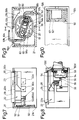
- input switches S1 and full-load switches S2 are also arranged in this order below the pusher guide 25 when one returns to the illustration in FIGS. 3 and 4, FIG. 3 showing the position of the pusher guide when the pusher handle is released in the off switch position.
- the handle axis 15 merges into a roughly rectangular inner handle part 33 provided with bevels and notches.
- inner wall formers 35 which are integral with the housing 21, are the structures for the input switch S1 and the full-load switch S2, arranged next to one another and each consisting of one Switch plunger 35a, 35b, which, in each case biased upward in the illustration of FIGS. 3 and 4, supports a metallic contact bridge 37a, 37b by a strong bias spring 36a, 36b.
- the switch plungers 35a, 35b each have upper sliding surfaces 38 which are operatively connected to a lower cam track 39, which comprises an inclined surface, on the inner pusher part.
- the inner pusher part 33 is pressed by its own strong bias spring 40 into the off-switch position to the right stop position, in which the two switch plungers 35a, 35b are shifted downward against their own spring pressure; in this position the upper sliding surfaces 38 of the two switch plungers are in the dot-dash position 38 'or 38 ".
- the free displacement path for the inner pusher part 33 is identified in FIG. 3 by the distance B; is now exerted by exerting pressure on the pusher handle 14 About the handle axis 15, the inner handle part 33 in the drawing plane of Fig.
- the second full-load switch S2 finally closes and bridges the electrical circuit of FIG. 16 with IC, as a result of which the motor M is supplied with the full supply voltage of the battery (no failing operation).
- the strong biasing spring 40 acting on the handle is guided over a larger part of its length even in the fully extended position as shown in FIG. 3 in a correspondingly shaped recess 41 in the inner handle part 33 and is tilted on the opposite side by a cup-like projecting socket 42 held.
- Fig. 3 shows that the (plus voltage from the battery) input tongue 11a (in one piece) merges into a first inner contact track 44 which lies with a horizontal bend 44a over both contact bridges 37a, 37b of the switches S1, S2 and in this way directly forms the respective input contact piece for these switches.
- the output contact pieces for these switches are formed directly from contact angles which originate from the substrate 22a of the hybrid module and if one looks at the illustration in FIG. 15a, then it can be seen that on the plate of the ceramic substrate 22a (among other components , which need not be dealt with or which will be explained further below), a first contact angle 32 is arranged which, with a surface 32a projecting vertically, directly forms the inner counter-contact piece for the input switch S1.
- the positive supply voltage reaches the circuit of the hybrid module 22 and is conducted via a lower contact surface connection to the (if desired also designed specifically for the customer) IC.
- the output of the IC is led via a thick wire bond 45 (preferably double because of the high currents) to a second contact angle 46, the leg 46a of which also protrudes vertically, both the output connection A1 of the control circuit and, as can be seen from FIG. 16, the inner contact piece. Connection for the second full load switch S2 forms.
- the free-wheeling diode D1 is also located on the ceramic substrate 22a, which, according to the circuit of FIG. 16, has the output connection of the contact angle 46, to which it is connected via the substrate, with a further ground connection contact angle 47 connects, namely also via a corresponding thick wire bond 48.
- the further contact angle 47 for the ground connection also has an upturned leg 47a, the leg 47a and the (double) leg 46a of the contact piece 46 each forming solder connections for output A1 for further internal contact tracks of the electronic switch which will be received shortly.
- the structure on the ceramic substrate is completed by the potentiometer tracks 48a, 48b printed on it and by two (tinned) connection surfaces 49 for the LEDs already mentioned above, for the optional connection to the connections 13a, 13b of FIG.
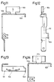
- the contact path 50 then runs, as the illustration in FIG. 6 in particular also shows more precisely, along the inner housing wall of the electronic switch and then forms a horizontally bent leg 50b, as best seen in the illustration in FIGS. 11, 12 and 13 can be.
- this contact path runs Two further tasks, namely that a flap 50c folded up from the horizontal leg 50b and bent flat forms the one (minus) connection pole for the right-left switchover in the head of the electronic switch housing, while a short leg 50d of the inner contact track 50 bent down again forms a first contact piece for the brake switch S4, which is still discussed (see FIG. 8).
- a control voltage made available to the motor by the IC in controlled operation and when the full-load switch S2 is open, this is led from the output contact angle 46a to a further inner contact path 52 as a further current conductor within the electronic switch housing.
- This second contact track 52 is shorter than the contact track 50 just discussed, because it does not need to be led outside; it begins, as shown in FIG. 6, as a further electrical connection 53, for example a manual soldering connection, as also at 51 and is referred to in the following only as such, with a transverse tab 52a which is soldered to the contact leg 46a, then runs adjacent and parallel to the contact track 50 (in FIG.
- the brake switch S4 itself is mounted with its bridge-shaped contact piece 53 on the inner pusher part 33, where the contact piece 53 (FIG. 8) is kept movable by a cover 54 of the pusher part 33, from its own small biasing spring 55 to an inner stop on the pusher part 33 in 8 is pushed to the right.
- the short-circuit switch S4 opens when the pusher guide 25 moves only slightly inwards, that is, before the input switch S1 can close its contacts.
- the low inherent mobility with its own bias spring 55 on the short-circuit switch S4 ensures that the electrical contact between the bridge-shaped switching element 53 and its two mating contact elements 50d, 52d (originating from the inner contact tracks 50 and 52) is in the off position of the under all circumstances Pusher is ensured because the switching piece 53 still retracts slightly against its own spring preload in the right stop position of the inner pusher part 33 and makes perfect contact; if the pusher is then pushed in again when the device is started, the bridge-like contact piece 53 arrives at a stop wall 56 corresponding to its inner shape (dashed line in FIG. 8), the contacts release and the input switch S1 closes next.
- FIG. 8 shows the angled shape of the potentiometer wiper 28, which runs along the potentiometer tracks 48a, 48b slides on the ceramic substrate 22a and connects these two tracks with one another, so that the potentiometer function indicated in FIG. 16 at P1 results for the assumed speed control of the battery-powered device.
- Fig. 7 shows again the position of the two inner contact tracks 50 and 52 with their respective lateral projections, the two connection areas (hand soldering points 51, 52 and 53) and the hybrid module 22, consisting of the ceramic substrate 22a with the two contact pieces for the switches S1 and S2 forming contact legs 32a, 46a and the encapsulation frame 23. It can be seen that the plate of the ceramic substrate 22a rests laterally on the inner opening edges 30a of the bottom cutout 30 of the housing and only the heat sink 29 protrudes from the housing for further contacting and heat dissipation.
- the housing is closed by a cover 21a and the individual parts of the electronic switch are designed and sorted so that the assembly can be carried out starting from the side of the then box-shaped housing which has been removed from the cover so that these parts are successively stacked or inserted into the housing, so that finally an automatic assembly, if desired, is also possible.
- the overall structure of the electronic switch is completed by the design of the right-left switch, as can best be seen in FIG. 9.
- an inner part housing 57 is inserted for the right-left switch S3, which contact tracks and receives contact angle for right-left switching or also rests on it, as shown in FIG. 10.
- the inner sub-housing 57 secures the relative position of the switch structures for the right-left switch which can best be seen from the top view of FIG. 9, the contact tabs 50c and 52c forming the power supply and bringing it up - the contact tab 50c for the ground connection and 52c Regarding the controlled (intermittent) direct current supply as a positive voltage connection or full supply voltage when switch S2 is closed.
- the two contact tabs 50c and 52c face each other and have a weak crescent shape; there are also two movable contact rockers 58a and 58b, which are in constant electrical contact with inner bearing clamp angles 59a, 59b, which in turn merge in one piece, preferably in one piece, into the tabs 12a, 12b leading to the motor connections.
- the receptacle by means of an inner partial housing 57 serves for the corresponding fixing and positioning of these switching elements, the contact rockers 58a, 58b having an approximately hemispherical curved shape and each being accommodated in the center of fork-shaped end regions 60 of the inner bearing clamps.
- the rocker switch 20 contains in its interior, on both sides, preloaded pressure pieces 62 by means of small springs 61, so that the contact between the contact rockers and the contact tabs 50c, 52c is flawless.
- the switching of the rocker switch 20 into its respective other angular position with the help of the switching lever 16 for the right-left switch can take place as shown in FIG. 5 above; a pivot bar 16a of the shift lever 16 detects, by means of the slot 18 mentioned, a pivot pin 19 projecting from its upper housing opening 63, which in turn is connected in a suitable manner to the pivotable rocker switch 20.
- the integration of the right-left switching area within the closed housing for the electronic switch is particularly advantageous, because in this way all working components are integrated in an unusually compact, externally sealed design without external wiring and, above all, sealed by the concept Housing walls of penetrating tongues need not be feared, even in rough operation, that foreign bodies or dust penetrate into the interior of the switch.
- an additional seal 64 (FIG. 3), which is arranged in the interior of the housing by a sealing groove receptacle 65 in the area of the handle axis 15 and surrounds this axis in a perfectly sealing manner.
- a further advantageous embodiment is that the sensible construction of the inner metallic strong band-shaped contact tracks, a possible deformation work that the very strong trigger spring could exert, for example, on the housing walls, is absorbed, so to speak, in the following way.
- the main cross leg 50b, 52b therefore runs parallel to the pretension spring 40 for the pusher, and since, when the pusher handle 14 is released, the inner pusher part 33 with the brake switch S4 which it supports rests against the short contact legs 50d, 52d via its contact bridge 53 and is fully relieved, that the pusher spring 40 (indirectly) is supported on both sides on the metallic contact tracks, because the cup-like socket 42 is a plastic molded part at least above the upwardly running contact track 50.
- the pusher spring 40 is therefore in its vigorous expansion drive towards both transverse sides of at least one of the Contact tracks held together, so to speak, and their effects safely kept away from the housing.
- the housing part wall insert 35 for the switches S1 and S2 extends with a preferably integrally molded inner part transverse wall 35 'in the drawing plane of FIG. 3 first to the left and then as a vertical leg 35''upwards, whereby at least with simultaneous covering the contact track 50, the cup-shaped holder 42 for the trigger spring 40 is formed.
- the IC module 22 with the heat sink protruding outward is initially inserted into the shape of the housing box; on its casting frame 23, the inner multi-walled housing structure 35, 35 ', 35' 'is placed, which in turn supports the plunger 35a, 35b including the switching mechanism and bias springs 36a, 36b of the two switches S1, S2.
- the inner pusher part 33 comes to rest above the switches S1, S2, the upper edges of which simultaneously form sliding surfaces 33a, 33b, 33c, with which the pusher part 33 slides along the lower surfaces of the transversely guided contact tracks 50, 52, that is to say their transverse legs 50b, 52b and also used as a sliding guide.
- the insert housing 57 for the right-left switchover is then located above it; If one looks here at the representation of FIG. 9, then one also recognizes that this partial housing with projections 57a, 57b penetrates corresponding openings 66 of the housing 21 or of the cover 21a closely (because of the dust-tightness) and thus also the upper motor connection plug-in tongues leads to the outside.
- the contact angle 32 serves for the power supply (+ U B connection) of the hybrid and at the same time as a fixed contact for the input switch S1.
- the contact angle 46 serves as an output connection of the circuit and at the same time as a further fixed contact for the full load switch S2 as a bypass switch for the IC.
- the upstanding leg 46a of this contact bracket 46 is designed in the manner of a double leg in order to simultaneously create a hand soldering point for connection to the shorter contact track 52. The second hand soldering point is then formed by the upstanding leg 47a of the contact angle 47 for the ground connection of the hybrid.
- a connection to the light-emitting diodes mentioned briefly above, for example for indicating overtemperature and undervoltage, can be established with leaf springs which resiliently rest on the connection surfaces 49 for the LEDs.
- the two potentiometer tracks 48a, 48b are connected by the fork-shaped grinder 28 and are bridged as the feed path increases to zero resistance. In this respect, no wiper tap is provided, and the potentiometer is implemented as a variable resistor.
- the control of the hybrid module works according to the pulse width modulation method; the current supplied to the motor via the right-left switch is increased or decreased by widening or narrowing current pulses, which are otherwise constant in height and frequency.
- the clock frequency of the current pulses is determined by the capacitor C1 according to FIG. 16; in a selected embodiment, which of course does not limit the invention, it can be 22 kHz.
- the pulse width is regulated with the potentiometer P1, the level of the resistance and thus the voltage present at the PWM input serving as a threshold for a voltage occurring at the SAW input (sawtooth generator).
- the structure of the remaining circuit elements grouped around the control module IC is completed by a freewheeling diode D1, which serves to protect the electronics when the battery is switched off by the input switch S1; the capacitor C3 smoothes out voltage pulses resulting from possible high current pulses at the line inductances and protects the IC against overvoltage, while the LED1 responds when the supply voltage of the battery is below one certain value has dropped, which is determined by the two resistors R3 and R4, and the LED2 signals an overload of the electronics (too hot).
- the resistors R1 and R2 serve to limit the diode current flowing through the light emitting diodes LED1 and LED2.
- control circuit introduces current regulation by temperature limitation; If the circuit module IC reaches a certain temperature, which can be, for example, between 140 and 170 ° C., then the LED1 lights up, and at the same time a temperature control controls the pulse width, and the stronger the chip temperature, the stronger.
- This temperature control protects the entire electronics from overtemperature; due to the very effective cooling, however, as tests have shown, it does not work in normal operation. It can be switched off arbitrarily anyway by switching to full load operation, which at the same time gives the IC the opportunity to cool down accordingly.
Landscapes
- Engineering & Computer Science (AREA)
- Power Engineering (AREA)
- Microelectronics & Electronic Packaging (AREA)
- Physics & Mathematics (AREA)
- Thermal Sciences (AREA)
- Battery Mounting, Suspending (AREA)
- Control Of Direct Current Motors (AREA)
- Details Of Measuring And Other Instruments (AREA)
- Rotary Switch, Piano Key Switch, And Lever Switch (AREA)
- Push-Button Switches (AREA)
Applications Claiming Priority (2)
| Application Number | Priority Date | Filing Date | Title |
|---|---|---|---|
| DE4038786A DE4038786A1 (de) | 1990-12-05 | 1990-12-05 | Vorrichtung zur steuerung oder regelung von durch akkus versorgter geraete |
| DE4038786 | 1990-12-05 |
Publications (2)
| Publication Number | Publication Date |
|---|---|
| EP0489343A2 true EP0489343A2 (fr) | 1992-06-10 |
| EP0489343A3 EP0489343A3 (fr) | 1994-02-09 |
Family
ID=6419652
Family Applications (1)
| Application Number | Title | Priority Date | Filing Date |
|---|---|---|---|
| EP91120215A Withdrawn EP0489343A2 (fr) | 1990-12-05 | 1991-11-26 | Dispositif de commande ou de régulation d'appareils alimentés par accumulateurs |
Country Status (5)
| Country | Link |
|---|---|
| US (1) | US5200657A (fr) |
| EP (1) | EP0489343A2 (fr) |
| JP (1) | JPH05256966A (fr) |
| KR (1) | KR920013861A (fr) |
| DE (1) | DE4038786A1 (fr) |
Cited By (8)
| Publication number | Priority date | Publication date | Assignee | Title |
|---|---|---|---|---|
| EP0732714A2 (fr) * | 1995-03-13 | 1996-09-18 | Marquardt GmbH | Commutateur électrique, notamment pour outils à main électrique |
| NL9500434A (nl) * | 1995-03-06 | 1996-10-01 | Capax B V | Koeling van een vermogenscomponent van een elektronische regelschakelaar. |
| EP0957497A2 (fr) * | 1998-05-12 | 1999-11-17 | Eaton Corporation | Interrupteur de commande d'un outil électrique à courant continu à vitesse variable |
| WO2007079716A1 (fr) * | 2006-01-09 | 2007-07-19 | Marquardt Gmbh | Commutateur électrique |
| EP1691385A3 (fr) * | 2005-02-09 | 2007-10-10 | Satori S-Tech Co., Ltd. | Interrupteur de déclenchement |
| WO2008083667A2 (fr) * | 2007-01-13 | 2008-07-17 | Marquardt Gmbh | Dispositif de commande pour moteur électrique |
| WO2009003703A3 (fr) * | 2007-07-04 | 2009-02-19 | Marquardt Gmbh | Dispositif de commande pour moteur électrique |
| DE102006061130B4 (de) * | 2006-01-09 | 2020-03-19 | Marquardt Gmbh | Elektrischer Schalter und Elektrowerkzeug mit einem solchen Schalter |
Families Citing this family (25)
| Publication number | Priority date | Publication date | Assignee | Title |
|---|---|---|---|---|
| DE4232402C5 (de) * | 1992-09-26 | 2005-10-27 | Marquardt Gmbh | Bremsschaltung für einen Elektromotor |
| DE4410312C2 (de) * | 1994-03-25 | 2000-01-13 | Bosch Gmbh Robert | Elektrische Handwerkzeugmaschine mit Potentiometer und Verfahren zum Einstellen des Potentiometers |
| DE4438045C2 (de) * | 1994-10-25 | 1996-11-07 | Atlas Copco Elektrowerkzeuge | Schalteinrichtung einer handgeführten Elektrowerkzeugmaschine |
| DE19635102B4 (de) * | 1996-08-30 | 2006-01-19 | Marquardt Gmbh | Elektrischer Schalter |
| US5835351A (en) * | 1997-05-30 | 1998-11-10 | Lucerne Products, Inc. | Modular D.C. tool switch assembly |
| DE19831458B4 (de) * | 1997-07-24 | 2009-04-02 | Marquardt Gmbh | Elektrischer Schalter, insbesondere für ein Akku-Elektrowerkzeug |
| US6049460A (en) * | 1999-07-19 | 2000-04-11 | Eaton Corporation | Trigger actuated control having supplemental heat sink |
| US6552904B2 (en) | 2001-08-13 | 2003-04-22 | Black & Decker Inc. | Power tool with heat sink assembly |
| US7949668B2 (en) * | 2001-08-20 | 2011-05-24 | Pardalis, Inc. | Common point authoring system for the complex sharing of hierarchically authored data objects in a distribution chain |
| DE10259569A1 (de) * | 2002-12-19 | 2004-07-01 | Hilti Ag | Elektrohandwerkzeugmaschine mit kontaktlosem elektrischen Handschalter |
| DE102005010129A1 (de) * | 2004-03-05 | 2005-09-15 | Marquardt Gmbh | Elektrische Schaltungsanordnung für ein Elektrowerkzeug |
| DE102005001748B4 (de) * | 2005-01-14 | 2019-01-24 | Marquardt Gmbh | Elektrischer Schalter und Elektrohandwerkzeug mit einem solchen Schalter |
| DE102005013762C5 (de) | 2005-03-22 | 2012-12-20 | Sew-Eurodrive Gmbh & Co. Kg | Elektronisches Gerät und Verfahren zur Bestimmung der Temperatur eines Leistungshalbleiters |
| NL1028778C2 (nl) * | 2005-04-15 | 2006-10-17 | Electrische App Nfabriek Capax | Regelschakeling met verminderde belasting voor een overbruggingsschakelaar. |
| JP5066874B2 (ja) * | 2006-09-19 | 2012-11-07 | オムロン株式会社 | トリガスイッチ |
| DE102007014120A1 (de) * | 2007-03-23 | 2008-09-25 | Ferm Bv | Stromversorgungspack |
| DE102008000704A1 (de) | 2007-04-24 | 2008-10-30 | Robert Bosch Gmbh | Elektrowerkzeug und Geräteschalter für ein Elektrowerkzeug |
| DE102007027898A1 (de) | 2007-06-18 | 2008-12-24 | Robert Bosch Gmbh | Elektrowerkzeug mit Kaltstartfunktion |
| JP5256904B2 (ja) * | 2008-07-24 | 2013-08-07 | オムロン株式会社 | トリガスイッチ |
| EP2652388A1 (fr) * | 2010-12-15 | 2013-10-23 | Illinois Tool Works, Inc. | Système de dissipateur de chaleur/connecteur pour diodes électroluminescentes |
| US9912020B2 (en) | 2013-03-12 | 2018-03-06 | Milwaukee Electric Tool Corporation | Battery pack with heat sink |
| ES2845604T3 (es) | 2014-02-18 | 2021-07-27 | Defond Components Ltd | Conjunto de conmutadores eléctricos |
| EP2946886B1 (fr) | 2014-03-28 | 2017-02-22 | Black & Decker Inc. | Module de commutation et de commande électronique pour un outil électrique |
| DE102016003150A1 (de) * | 2016-03-16 | 2017-09-21 | Andreas Stihl Ag & Co. Kg | Handgeführtes Arbeitsgerät mit einem Elektromotor |
| US10541588B2 (en) | 2017-05-24 | 2020-01-21 | Black & Decker Inc. | Electronic power module for a power tool having an integrated heat sink |
Citations (6)
| Publication number | Priority date | Publication date | Assignee | Title |
|---|---|---|---|---|
| US4205434A (en) * | 1977-11-08 | 1980-06-03 | Eaton Corporation | Trigger speed control switch subassembly and method of making |
| EP0048124A2 (fr) * | 1980-09-12 | 1982-03-24 | Skil Nederland B.V. | Dispositif de commutateur de contrôle de vitesse |
| EP0213830A2 (fr) * | 1985-08-09 | 1987-03-11 | Black & Decker Inc. | Interrupteur à gâchette pour vitesses variables |
| US4719395A (en) * | 1986-12-22 | 1988-01-12 | Omron Tateisi Electronics Co. | Variable speed control switch for an electric tool including a DC motor |
| WO1989009997A1 (fr) * | 1988-04-15 | 1989-10-19 | Lucerne Products, Inc. | Commutateur d'inversion a courant continu |
| US4937705A (en) * | 1989-05-08 | 1990-06-26 | Eaton Corporation | Variable power control apparatus having external heat sink mounting battery clips |
Family Cites Families (25)
| Publication number | Priority date | Publication date | Assignee | Title |
|---|---|---|---|---|
| US3721879A (en) * | 1965-07-02 | 1973-03-20 | Arrow Hart Inc | Power control for portable electric tool |
| DE1763455B1 (de) * | 1968-05-31 | 1972-03-09 | Metabowerke Kg | Vorrichtung zur einstellung des sollwertes an einem elektroni schen drehzahlregler eines ein elektrowerkzeug antreibenden elektromotors |
| US3585476A (en) * | 1968-07-19 | 1971-06-15 | Cutler Hammer Inc | Trigger switch speed control with electrical feedback |
| US3590194A (en) * | 1969-09-19 | 1971-06-29 | Skil Corp | Contact- and circuit-mounting board for trigger-operated switch unit |
| DE2629723C3 (de) * | 1976-07-02 | 1980-07-03 | Scintilla Ag, Solothurn (Schweiz) | Handbetätigbare Einbauschaltvorrichtung für elektrische Maschinen |
| US4097705A (en) * | 1977-08-05 | 1978-06-27 | The Singer Company | Quick lock-release mechanism for a trigger switch |
| US4241297A (en) * | 1978-11-20 | 1980-12-23 | Eaton Corporation | Double-pole trigger speed control switch |
| EP0033353A1 (fr) * | 1980-02-05 | 1981-08-12 | Black & Decker Inc. | Procédé et appareil pour contrôler la vitesse de rotation d'une perceuse, d'un fleuret à percussion ou d'un marteau rotatif |
| US4292571A (en) * | 1980-02-14 | 1981-09-29 | Black & Decker Inc. | Control device for controlling the rotational speed of a portable power tool |
| US4412158A (en) * | 1980-02-21 | 1983-10-25 | Black & Decker Inc. | Speed control circuit for an electric power tool |
| US4348603A (en) * | 1981-01-29 | 1982-09-07 | Black & Decker Inc. | Printed-circuit board and trigger-switch arrangement for a portable electric tool |
| JPS59165941A (ja) * | 1983-03-11 | 1984-09-19 | Hitachi Ltd | インバ−タ駆動回転電機 |
| DE3338764A1 (de) * | 1983-10-26 | 1985-05-09 | Robert Bosch Gmbh, 7000 Stuttgart | Schaltungsanordnung zum ein- und ausschalten und ueberwachen elektrischer verbraucher |
| US4556803A (en) * | 1984-02-29 | 1985-12-03 | Electro-Matic Staplers, Inc. | Trigger switch circuit for solenoid-actuated electric hand tool |
| US4737661A (en) * | 1985-08-09 | 1988-04-12 | Black & Decker Inc. | Variable speed trigger switch |
| US4755706A (en) * | 1986-06-19 | 1988-07-05 | General Electric Company | Piezoelectric relays in sealed enclosures |
| DE3629976A1 (de) * | 1986-09-03 | 1988-04-07 | Hueco Gmbh Fabrik Fuer Interna | Spannungsregler fuer generatoren |
| US4739209A (en) * | 1986-10-06 | 1988-04-19 | Aircraft Parts Corp. | Starter-generator brush |
| US4777393A (en) * | 1987-07-17 | 1988-10-11 | The Singer Company | Modular tool system switch and actuator assembly |
| US4903318A (en) * | 1987-11-13 | 1990-02-20 | Omron Tateisi Electronics Co. | Electric switch system for a power tool |
| DE3804679C2 (de) * | 1988-02-15 | 1993-12-02 | Bosch Gmbh Robert | Überlastschutz für Elektromotoren |
| JP2668919B2 (ja) * | 1988-03-11 | 1997-10-27 | 松下電器産業株式会社 | 送風電動機 |
| DE3815883A1 (de) * | 1988-05-10 | 1989-11-23 | Kautt & Bux Kg | Geraeteschalter |
| DE8814721U1 (fr) * | 1988-11-25 | 1989-01-26 | Proxxon Werkzeug Gmbh, 5561 Niersbach, De | |
| US5014793A (en) * | 1989-04-10 | 1991-05-14 | Measurement Specialties, Inc. | Variable speed DC motor controller apparatus particularly adapted for control of portable-power tools |
-
1990
- 1990-12-05 DE DE4038786A patent/DE4038786A1/de active Granted
-
1991
- 1991-11-22 US US07/797,441 patent/US5200657A/en not_active Expired - Fee Related
- 1991-11-26 EP EP91120215A patent/EP0489343A2/fr not_active Withdrawn
- 1991-12-02 KR KR1019910021959A patent/KR920013861A/ko not_active Application Discontinuation
- 1991-12-05 JP JP3322079A patent/JPH05256966A/ja active Pending
Patent Citations (6)
| Publication number | Priority date | Publication date | Assignee | Title |
|---|---|---|---|---|
| US4205434A (en) * | 1977-11-08 | 1980-06-03 | Eaton Corporation | Trigger speed control switch subassembly and method of making |
| EP0048124A2 (fr) * | 1980-09-12 | 1982-03-24 | Skil Nederland B.V. | Dispositif de commutateur de contrôle de vitesse |
| EP0213830A2 (fr) * | 1985-08-09 | 1987-03-11 | Black & Decker Inc. | Interrupteur à gâchette pour vitesses variables |
| US4719395A (en) * | 1986-12-22 | 1988-01-12 | Omron Tateisi Electronics Co. | Variable speed control switch for an electric tool including a DC motor |
| WO1989009997A1 (fr) * | 1988-04-15 | 1989-10-19 | Lucerne Products, Inc. | Commutateur d'inversion a courant continu |
| US4937705A (en) * | 1989-05-08 | 1990-06-26 | Eaton Corporation | Variable power control apparatus having external heat sink mounting battery clips |
Cited By (11)
| Publication number | Priority date | Publication date | Assignee | Title |
|---|---|---|---|---|
| NL9500434A (nl) * | 1995-03-06 | 1996-10-01 | Capax B V | Koeling van een vermogenscomponent van een elektronische regelschakelaar. |
| EP0732714A2 (fr) * | 1995-03-13 | 1996-09-18 | Marquardt GmbH | Commutateur électrique, notamment pour outils à main électrique |
| EP0732714A3 (fr) * | 1995-03-13 | 1997-10-22 | Marquardt Gmbh | Commutateur électrique, notamment pour outils à main électrique |
| US5798584A (en) * | 1995-03-13 | 1998-08-25 | Marquardt Gmbh | Electric switch, especially for electric hand tools |
| EP0957497A2 (fr) * | 1998-05-12 | 1999-11-17 | Eaton Corporation | Interrupteur de commande d'un outil électrique à courant continu à vitesse variable |
| EP0957497A3 (fr) * | 1998-05-12 | 2000-08-23 | Eaton Corporation | Interrupteur de commande d'un outil électrique à courant continu à vitesse variable |
| EP1691385A3 (fr) * | 2005-02-09 | 2007-10-10 | Satori S-Tech Co., Ltd. | Interrupteur de déclenchement |
| WO2007079716A1 (fr) * | 2006-01-09 | 2007-07-19 | Marquardt Gmbh | Commutateur électrique |
| DE102006061130B4 (de) * | 2006-01-09 | 2020-03-19 | Marquardt Gmbh | Elektrischer Schalter und Elektrowerkzeug mit einem solchen Schalter |
| WO2008083667A2 (fr) * | 2007-01-13 | 2008-07-17 | Marquardt Gmbh | Dispositif de commande pour moteur électrique |
| WO2009003703A3 (fr) * | 2007-07-04 | 2009-02-19 | Marquardt Gmbh | Dispositif de commande pour moteur électrique |
Also Published As
| Publication number | Publication date |
|---|---|
| US5200657A (en) | 1993-04-06 |
| DE4038786A1 (de) | 1992-06-11 |
| KR920013861A (ko) | 1992-07-29 |
| JPH05256966A (ja) | 1993-10-08 |
| EP0489343A3 (fr) | 1994-02-09 |
| DE4038786C2 (fr) | 1993-06-17 |
Similar Documents
| Publication | Publication Date | Title |
|---|---|---|
| EP0489343A2 (fr) | Dispositif de commande ou de régulation d'appareils alimentés par accumulateurs | |
| EP0512316B1 (fr) | Interrupteur, en particulier interrupteur de la batterie pour outils électriques manuel | |
| EP1253808B1 (fr) | Dispositif de chauffage électrique, utilisé en particulier dans les véhicules | |
| EP1374653B1 (fr) | Dispositif de commande pour un moteur electrique | |
| EP1873800B1 (fr) | Machine-outil électrique et interrupteur correspondant | |
| DE19508925A1 (de) | Elektrischer Schalter, insbesondere für Elektrohandwerkzeuge | |
| DE4031051C2 (de) | Modul mit mindestens einem Halbleiterschaltelement und einer Ansteuerschaltung | |
| EP1119899A1 (fr) | Configuration d'un redresseur polyphase | |
| EP1586223B1 (fr) | Connecteur electrique destine notamment au commutateur d'un outil electrique | |
| DE102016223889A1 (de) | Stapelbares Elektronikmodul, Wechselrichter und Kraftfahrzeugantriebsstrang | |
| DE102008062514A1 (de) | Halbleitermodul-Montagekonstruktion | |
| WO2014206665A1 (fr) | Circuit électrique, et procédé de production d'un circuit électrique pour la commande d'une charge | |
| DE102009019285A1 (de) | Beleuchtungssystem mit mindestens einem Leuchtband | |
| DE10296619T5 (de) | Leistungsmodul | |
| DE4038785C2 (fr) | ||
| DE202017104144U1 (de) | Elektrisch angetriebenes Arbeitsgerät | |
| DE4038787C2 (fr) | ||
| DE19522126A1 (de) | Elektronischer Lastschalter für ein Kraftfahrzeug | |
| EP2108216B1 (fr) | Dispositif de commande pour moteur électrique | |
| DE10212449A1 (de) | Träger für eine elektrische Schaltung, insbesondere für einen elektrischen Schalter | |
| DE102009009965B4 (de) | Elektrischer Schalter, insbesondere Elektrowerkzeugschalter | |
| DE3511895C2 (fr) | ||
| DE3628556C1 (en) | Semiconductor device | |
| DE60028155T2 (de) | Leistungsumschaltvorrichtung | |
| EP1973023A1 (fr) | Kit d'alimentation en courant |
Legal Events
| Date | Code | Title | Description |
|---|---|---|---|
| PUAI | Public reference made under article 153(3) epc to a published international application that has entered the european phase |
Free format text: ORIGINAL CODE: 0009012 |
|
| AK | Designated contracting states |
Kind code of ref document: A2 Designated state(s): AT BE CH DE DK ES FR GB GR IT LI LU NL SE |
|
| PUAL | Search report despatched |
Free format text: ORIGINAL CODE: 0009013 |
|
| RHK1 | Main classification (correction) |
Ipc: H01H 9/06 |
|
| AK | Designated contracting states |
Kind code of ref document: A3 Designated state(s): AT BE CH DE DK ES FR GB GR IT LI LU NL SE |
|
| STAA | Information on the status of an ep patent application or granted ep patent |
Free format text: STATUS: THE APPLICATION IS DEEMED TO BE WITHDRAWN |
|
| 18D | Application deemed to be withdrawn |
Effective date: 19940601 |