EP0489280B1 - Fördereinheit für ein Beatmungsgerät - Google Patents
Fördereinheit für ein Beatmungsgerät Download PDFInfo
- Publication number
- EP0489280B1 EP0489280B1 EP91119314A EP91119314A EP0489280B1 EP 0489280 B1 EP0489280 B1 EP 0489280B1 EP 91119314 A EP91119314 A EP 91119314A EP 91119314 A EP91119314 A EP 91119314A EP 0489280 B1 EP0489280 B1 EP 0489280B1
- Authority
- EP
- European Patent Office
- Prior art keywords
- piston
- cylinder
- bag
- membrane
- rolling
- Prior art date
- Legal status (The legal status is an assumption and is not a legal conclusion. Google has not performed a legal analysis and makes no representation as to the accuracy of the status listed.)
- Expired - Lifetime
Links
Images
Classifications
-
- A—HUMAN NECESSITIES
- A61—MEDICAL OR VETERINARY SCIENCE; HYGIENE
- A61M—DEVICES FOR INTRODUCING MEDIA INTO, OR ONTO, THE BODY; DEVICES FOR TRANSDUCING BODY MEDIA OR FOR TAKING MEDIA FROM THE BODY; DEVICES FOR PRODUCING OR ENDING SLEEP OR STUPOR
- A61M16/00—Devices for influencing the respiratory system of patients by gas treatment, e.g. mouth-to-mouth respiration; Tracheal tubes
- A61M16/0057—Pumps therefor
- A61M16/0072—Tidal volume piston pumps
-
- A—HUMAN NECESSITIES
- A61—MEDICAL OR VETERINARY SCIENCE; HYGIENE
- A61M—DEVICES FOR INTRODUCING MEDIA INTO, OR ONTO, THE BODY; DEVICES FOR TRANSDUCING BODY MEDIA OR FOR TAKING MEDIA FROM THE BODY; DEVICES FOR PRODUCING OR ENDING SLEEP OR STUPOR
- A61M16/00—Devices for influencing the respiratory system of patients by gas treatment, e.g. mouth-to-mouth respiration; Tracheal tubes
- A61M16/0057—Pumps therefor
- A61M16/006—Tidal volume membrane pumps
Definitions
- the invention relates to a delivery unit for a respirator with a piston-cylinder unit as a drive device, in which a piston is sealed against a cylinder by a cup-shaped bag roll membrane and a roll membrane arranged symmetrically to the bag roll membrane, with a working chamber enclosed by the bag roll membrane, which has a working chamber on one end face of the cylinder attached connecting plate as a fixed chamber part and an end plate of the piston as a movable chamber part, the bag roll membrane with its bottom surface abutting the end plate of the piston and with its open end on the end face of the cylinder, with an inner space that moves with the piston movement between the roll membranes , which is enclosed on the one hand by a piston wall of the piston and a cylinder wall of the cylinder and on the other hand by folds of the rolling membranes and is set to a pressure which is lower than that of the working chamber
- a delivery unit for a respirator is known from US Pat. No. 4,010,761, which has a piston-cylinder unit as the drive device with two roller membranes arranged symmetrically to one another for sealing the piston against the cylinder.
- One of the roll membranes is designed as a pot-shaped bag roll membrane and is attached to one of the end faces of the cylinder with a connecting plate.
- the bag roll membrane separates a volume-adjustable working chamber from the cylinder contents.
- the bottom of the bag roll membrane lies on the piston of the piston-cylinder unit which executes the breathing gas delivery stroke.
- a disadvantage of the known conveyor unit is that the bag roll membrane and the connecting plate have to be removed individually from the drive device in order to clean parts carrying breathing gas.
- a delivery unit for a respirator with a piston-cylinder unit as a drive device has become known from DE-A1 38 17 091.
- the piston guided in a cylinder is sealed off from the cylinder by a pair of roller membranes arranged symmetrically to one another, which divides the cylinder contents into a prechamber and a working chamber.
- the interior enclosed by the roll membranes is kept under a pressure which is higher than the pressure in both the antechamber and in the working chamber and on the concave inner sides of the folds the roll membrane is in contact, which ensures that the folds are formed consistently and lie flat against the walls of the piston and cylinder throughout the breath. If, on the other hand, the convex outer sides of the folds face each other, the interior is kept at a negative pressure in relation to the adjacent chambers. It is possible to check the tightness of the rolling membrane during operation by monitoring the pressure in the interior, so that leaks can be recognized immediately.
- the piston is moved in an oscillatory manner by a drive unit and the breathing gas displaced from the working chamber during the working stroke is conveyed to a breathing system via a connecting piece attached to the connecting plate.
- Accurate dosing of both small and large tidal volumes is possible because the delivery unit has a low compliance due to the rigid piston and cylinder wall and the total gas volume from the working chamber is expressed in the top dead center of the piston.
- the compliance of the rolling diaphragms is of minor importance, since it is only effective in the edge area in the gap between the piston and the cylinder.
- a ventilator is known with a volume-adjustable chamber designed as a bellows, which is set in oscillatory motion by a drive means, and can be coupled in a rack-like manner with the ventilator.
- the bellows is connected to the movable part of the drive via fastening means, which are designed here as magnetic couplings. Due to the insert-like construction, the parts that come into contact with the breathing gas, e.g. the bellows, removed and sterilized separately from the ventilator.
- the invention has for its object to improve a delivery unit for a respirator in such a way that with precise dosing of both large and small breathing volumes with the same working chamber volume, the breathing gas-carrying parts can be easily inserted into and removed from the drive device.
- connection plate has a fastening means into which the open end of the bag roll membrane can be buttoned, so that the bag roll membrane, together with the connection plate, can be inserted into the cylinder in the manner of a insert.
- a rolling membrane in the piston-cylinder unit with two rolling membranes, a rolling membrane is designed as a pot-shaped bag rolling membrane connected to the connector, which can be inserted as a working chamber into the drive device and the Interior space between the roll membranes is connected to a vacuum source and is kept at a pressure level below the pressure in the working chamber. Due to the negative pressure between the interior and the working chamber, the bag roll membrane lies against the cylinder wall and the end plate of the piston, while at the same time the folds form between the piston wall and the cylinder wall.
- the vacuum in the interior is reduced to the adhesive pressure in order to attach the bottom surface of the bag roll membrane to the end plate of the piston.
- the adhesive pressure depends on the diameter of the piston and the cylinder and the volume of the breathing gas conveyed by the bag roll membrane. Experiments have shown that for the practice-relevant respiratory stroke volumes the adhesive pressure is about 150 millibars below the average pressure prevailing in the working chamber.
- the attachment of the bottom surface of the bag roll membrane on the face plate of the piston via the adhesive pressure in the Interior also causes the bag roll membrane to be automatically centered within the cylinder during the first piston stroke. If, for example, the bag roll membrane was inserted canted into the cylinder, it initially lies against the cylinder wall and the end plate of the piston under the effect of the adhesive pressure.
- the piston is moved to the bottom dead center, the folds form between the piston and cylinder walls, causing the bag roll membrane to be pulled into the working position.
- an adhesive coating between the bottom surface of the bag roll membrane and the end plate of the piston as the fastening means.
- the adhesive coating ensures adhesion regardless of the pressure in the interior. If, for example, a fault occurs within the vacuum source so that no negative pressure can be generated in the interior, ventilation with the piston-cylinder unit is nevertheless possible due to the adhesive coating.
- the adhesive coating can be applied over the entire surface of the bottom surface and the end plate or in segments as a punctiform or circular coating.
- the upper end of the bag roll membrane is expediently buttoned into a projection of the connection plate.
- connection plate design the connection plate as a breathing system which, together with the bag roll membrane, can be inserted into the cylinder as a self-contained working chamber.
- the breathing gas-carrying parts of the ventilator can be inserted into or removed from the cylinder as a compact module.
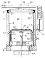
- a cylinder (1) is shown, the end faces of which are closed by a base plate (2) and a connecting plate (3).
- a piston (4) is received on a piston rod (5) guided in an axial bearing (6), which is connected to a drive device (7).
- the piston wall (28) is sealed off from the cylinder (1) with a rolling membrane (9) and a bag rolling membrane (8), the open end (30) of the bag rolling membrane (8) being buttoned into a projection (33) of the connecting plate (3) and the rolling membrane (9) is clamped between the cylinder (1) and the base plate (2).
- the projection (33) of the connection plate (3) sits by the folded bag roll membrane (8) sealingly on one end of the cylinder (1).
- the line (13) opens into a distributor (17), which is designed as a longitudinal groove in the cylinder wall (29) and serves to connect the interior (12) and the line (13) in every position of the piston (4). to manufacture.
- the roller membranes (8, 9) divide the interior of the cylinder (1) into a prechamber (18) which is connected to the environment via a passage (19), and into a working chamber (20) in which the ventilation pressure generated by the stroke movement of the piston (4) prevails.
- the piston (4) has on its side facing the working chamber (20) an end plate (21) against which the bottom surface (31) of the bag roll membrane (8) bears.
- the breathing gas displaced during the working stroke can flow through the connection piece (22) attached to the connection plate (3) to a breathing system (25) of a ventilator (not shown).
- the breathing system (25) has connections (26, 27) for an inhalation line and exhalation line, not shown, via which the breathing gas is supplied.
- a pressure measuring device (15) is connected to the line (13), the measuring signal of which is passed on to a control unit (23) which at the same time records the setpoint value supplied by the vacuum source (14).
- a display unit (24) shows the current state of the vacuum in the interior (12) and emits any necessary warning signals.
- the conveying device is started up in such a way that the breathing system (25) with the connecting plate (3) and the bag rolling membrane (8) is placed on the cylinder (1) and the vacuum source (14) is switched on. Due to the negative pressure which arises in the interior (12), the bag roll membrane (8) lies against the cylinder wall (29) and the bottom surface (31) of the bag roll membrane (8) lies against the end plate (21) of the piston (4).
- the connecting plate (3) is also pressed against the end face of the cylinder (1) by the negative pressure, the bag roll membrane (8) located at the separation point between the connecting plate (3) and the cylinder (1) provides a gas-tight seal.
- the fold (11) of the bag roll membrane is centered between the piston wall (28) and the cylinder wall (29) under the effect of the negative pressure, so that a correct rolling of the folds (10, 11) is guaranteed in the subsequent piston strokes.
- a vacuum or adhesive pressure of approximately 150 millibars is required for a uniform formation of folds in the rolling membranes (8, 9) and firm adherence of the bottom surface (31) to the end plate (21).
- a punctiform adhesive coating (32) is provided on the contact surface.
Landscapes
- Health & Medical Sciences (AREA)
- Emergency Medicine (AREA)
- Pulmonology (AREA)
- Engineering & Computer Science (AREA)
- Anesthesiology (AREA)
- Biomedical Technology (AREA)
- Heart & Thoracic Surgery (AREA)
- Hematology (AREA)
- Life Sciences & Earth Sciences (AREA)
- Animal Behavior & Ethology (AREA)
- General Health & Medical Sciences (AREA)
- Public Health (AREA)
- Veterinary Medicine (AREA)
- Respiratory Apparatuses And Protective Means (AREA)
Description
- Die Erfindung betrifft eine Fördereinheit für ein Beatmungsgerät mit einer Kolben-Zylindereinheit als Antriebvorrichtung, bei welcher ein Kolben gegenüber einem Zylinder durch eine topfförmige Beutelrollmembran und eine symmetrisch zur Beutelrollmembran angeordnete Rollmembran abgedichtet ist, mit einer von der Beutelrollmembran umschlossenen Arbeitskammer, welche eine auf einer Stirnseite des Zylinders angebrachte Anschlußplatte als feststehendes Kammerteil und eine Stirnplatte des Kolbens als bewegliches Kammerteil besitzt, wobei die Beutelrollmembran mit ihrer Bodenfläche an der Stirnplatte des Kolbens und mit ihrem offenen Ende an der Stirnseite des Zylinders anliegt, mit einem bei der Kolbenbewegung mitlaufenden Innenraum zwischen den Rollmembranen, der einerseits von einer Kolbenwand des Kolbens und einer Zylinderwand des Zylinders und andererseits von Falten der Rollmembranen umschlossen ist und auf einen gegenüber der Arbeitskammer abgesenkten Druck eingestellt ist
- Aus der US 4,010,761 ist eine Fördereinheit für ein Beatmungsgerät bekannt, welche eine Kolben-Zylinder-Einheit als Antriebsvorrichtung mit zwei symmetrisch zueinander angeordneten Rollmembranen zur Abdichtung des Kolbens gegenüber dem Zylinder besitzt.
- Eine der Rollmembranen ist als topfförmige Beutelrollmembran ausgeführt und mit einer Anschlußplatte an einer der Stirnseiten des Zylinders befestigt. Die Beutelrollmembran trennt aus dem Zylinderinhalt eine volumenveränderbare Arbeitskammer ab. Der Boden der Beutelrollmembran liegt auf dem den Atemgasförderhub ausführenden Kolben der Kolben-Zylinder-Einheit auf.
- Nachteilig bei der bekannten Fördereinheit ist, daß zur Reinigung von atemgasführenden Teilen die Beutelrollmembran und die Anschlußplatte einzeln aus der Antriebsvorrichtung entfernt werden müssen.
- Eine Fördereinheit für ein Beatmungsgerät mit einer Kolben-Zylindereinheit als Antriebsvorrichtung ist aus der DE-A1 38 17 091 bekanntgeworden. Der in einem Zylinder geführte Kolben ist gegenüber dem Zylinder durch ein symmetrisch zueinander angeordnetes Rollmembranpaar abgedichtet, welches den Zylinderinhalt in eine Vorkammer und eine Arbeitskammer unterteilt.
- Um den Verschleiß der Rollmembranen durch ein sauberes Abrollen der Falten zu verringern, wird der von den Rollmembranen gemeinsam eingeschlossene Innenraum unter einem Druck gehalten, der höher ist als der Druck sowohl in der Vorkammer als auch in der Arbeitskammer und der auf den konkaven Innenseiten der Falten der Rollmembran ansteht, wodurch während des gesamten Atemhubs für eine gleichbleibende Ausbildung der Falten und ihr glattes Anliegen an den Wänden von Kolben und Zylinder gesorgt ist. Sind hingegen die konvexen Außenseiten der Falten einander zugekehrt, ist der Innenraum auf einem Unterdruck gegenüber den benachbarten Kammern gehalten. Eine Dichtigkeitskontrolle der Rollmembran während des Betriebes ist dadurch möglich, daß der Druck im Innenraum überwacht wird und so Leckagen unverzüglich erkennbar sind. Während der Beatmung wird der Kolben über eine Antriebseinheit oszillatorisch bewegt und dabei das während des Arbeitshubes aus der Arbeitskammer verdrängte Atemgas über einen an der Anschlußplatte angebrachten Anschlußstutzen zu einem Atemsystem befördert. Hierbei ist eine genaue Dosierung sowohl von kleinen als auch großen Atemvolumina möglich, da die Fördereinheit, bedingt durch die starre Kolben- und Zylinderwand, eine geringe Compliance hat und im oberen Totpunkt des Kolbens das gesamte Gasvolumen aus der Arbeitskammer ausgedrückt ist. Die Compliance der Rollmembranen ist von untergeordneter Bedeutung, da diese nur im Randbereich im Spalt zwischen Kolben und Zylinder wirksam ist.
- Bei der bekannten Kolben-Zylindereinheit ist es von Nachteil, daß während des Betriebs die gesamte Arbeitskammer, die begrenzt ist durch die Stirnplatte des Kolbens, die Innenseite der Anschlußplatte und die Zylinderwand, vom Atemgas durchspült wird und deswegen die gesamte Kolben-Zylindereinheit bei der Geräteaufbereitung gereinigt und desinfiziert werden muß. Sollen bei einem Patientenwechsel die atemgasführenden Teile des Beatmungsgerätes ausgetauscht werden, muß immer eine komplette Kolben-Zylindereinheit vorgehalten werden, obwohl nur die Arbeitskammer mit dem Atemgas in Berührung gekommen ist. Dies erschwert die Handhabung im klinischen Routinebetrieb.
- Aus der DE-B2 26 47 343 ist ein Beatmungsgerät bekannt mit einer als Faltenbalg ausgeführten volumenveränderbaren Kammer, die von einem Antriebsmittel in oszillatorische Bewegung versetzt wird, und einschubartig mit dem Beatmungsgerät gekoppelt werden kann. Der Faltenbalg ist über Befestigungsmittel, die hier als Magnetkupplungen ausgeführt sind, mit dem beweglichen Teil des Antriebs verbunden. Durch die einschubartige Konstruktion können die mit dem Atemgas in Berührung kommenden Teile, wie z.B. der Faltenbalg, entnommen und losgelöst vom Beatmungsgerät sterilisiert werden.
- Bei dem bekannten Beatmungsgerät ist es von Nachteil, daß mit einer einzigen Faltenbalg-Größe als volumenveränderbare Arbeitskammer nur eine ungenaue Dosierung des Atemhubvolumens möglich ist, da der Faltenbalg aufgrund seiner Eigenelastizität eine hohe Compliance besitzt, wodurch speziell die Dosierung von kleinen Atemhubvolumina - wie sie zur Beatmung von Kleinkindern notwendig sind - sehr ungenau wird. Es ist zwar von anderen Beatmungsgeräten bekannt, in diesen Fällen den Faltenbalg mit großem Arbeitskammer-Volumen gegen eine Ausführung mit kleinerem Arbeitskammer-Volumen auszutauschen, hierdurch wird jedoch die Handhabung erschwert, z.B. wenn während einer Beatmung aus therapeutischen Gründen kurzfristig ein höheres Atemhubvolumen appliziert werden muß. Außerdem sind besondere Überwachungseinrichtungen notwendig, die dem Anwender anzeigen, welcher Faltenbalg gerade im Beatmungsgerät eingesetzt ist.
- Der Erfindung liegt die Aufgabe zugrunde, eine Fördereinheit für ein Beatmungsgerät derart zu verbessern, daß bei genauer Dosierung sowohl von großen und von kleinen Atemhubvolumina mit dem gleichen Arbeitskammer-Volumen, die atemgasführenden Teile einfach in die Antriebsvorrichtung einsetzbar und aus dieser wieder entnehmbar sind.
- Die Lösung der Aufgabe erfolgt dadurch, daß die Anschlußplatte ein Befestigungsmittel aufweist, in welches das offene Ende der Beutelrollmembran einknöpfbar ist, so daß die Beutelrollmembran, zusammen mit der Anschlußplatte, einschubartig in den Zylinder einsetzbar ist.
- Der Vorteil der Erfindung besteht im wesentlichen darin, daß bei der Kolben-Zylindereinheit mit zwei Rollmembranen eine Rollmembran als topfförmige, mit dem Anschlußstück verbundene Beutelrollmembran ausgeführt ist, welche als Arbeitskammer einschubartig in die Antriebsvorrichtung einsetzbar ist und der Innenraum zwischen den Rollmembranen an eine Vakuumquelle angeschlossen und auf einem Druckniveau unterhalb des Druckes in der Arbeitskammer gehalten ist. Durch den Unterdruck zwischen dem Innenraum und der Arbeitskammer legt sich die Beutelrollmembran an die Zylinderwand und die Stirnplatte des Kolbens an, während sich gleichzeitig die Falten zwischen Kolbenwand und Zylinderwand ausbilden.
- Die Kombination der Beutelrollmembran mit einer Kolben-Zylindereinheit als Antriebsvorrichtung führt zu der hohen Dosiergenauigkeit wie bei einer Kolben-Zylindereinheit mit fest eingebautem Rollmembranpaar, während gleichzeitig eine leichte Entnahme der atemgasführenden Teile möglich ist, wie bei einer einschubartigen Konstruktion mit Faltenbalg. Mit der erfindungsgemäßen Fördervorrichtung können sowohl große Atemhubvolumina für Erwachsene als auch kleine Atemhubvolumina für Kleinkinder appliziert werden.
- Zur Befestigung der Bodenfläche der Beutelrollmembran an der Stirnplatte des Kolbens ist der Unterdruck im Innenraum auf den Haftdruck abgesenkt. Der Haftdruck ist abhängig von dem Durchmesser des Kolbens und des Zylinders und dem Rauminhalt des von der Beutelrollmembran geförderten Atemgases. Versuche haben gezeigt, daß für die praxisrelevanten Atemhubvolumina der Haftdruck etwa um 150 Millibar unter dem in der Arbeitskammer herrschenden mittleren Druck liegt. Die Befestigung der Bodenfläche der Beutelrollmembran auf der Stirnplatte des Kolbens über den Haftdruck im Innenraum bewirkt außerdem eine automatische Zentrierung der Beutelrollmembran innerhalb des Zylinders während des ersten Kolbenhubes. Wurde beispielsweise die Beutelrollmembran verkantet in den Zylinder eingesetzt, legt sie sich unter der Wirkung des Haftdruckes zunächst an die Zylinderwand und die Stirnplatte des Kolbens. Wird der Kolben in den unteren Totpunkt bewegt, bilden sich zwischen Kolben- und Zylinderwand die Falten aus, wodurch die Beutelrollmembran in die Arbeitsposition gezogen wird. Es ist zweckmäßig, als Befestigungsmittel eine Adhäsionsbeschichtung zwischen der Bodenfläche der Beutelrollmembran und der Stirnplatte des Kolbens vorzusehen. Durch die Adhäsionsbeschichtung ist eine Haftung vorhanden unabhängig von dem Druck im Innenraum. Tritt beispielsweise eine Störung innerhalb der Vakuumquelle auf, so daß kein Unterdruck im Innenraum erzeugt werden kann, ist durch die Adhäsionsbeschichtung trotzdem eine Beatmung mit der Kolben-Zylindereinheit möglich. Die Adhäsionsbeschichtung kann ganzflächig auf der Bodenfläche und der Stirnplatte oder segmentartig als punkt- oder kreisringförmige Beschichtung aufgebracht sein.
- Vorteilhafte Ausgestaltungen der Erfindung sind in den Unteransprüchen angegeben.
- In zweckmäßiger Weise ist das obere Ende der Beutelrollmembran in einen Vorsprung der Anschlußplatte eingeknöpft.
- Eine zweckmäßige Ausgestaltung der Erfindung ist, die Anschlußplatte als ein Atemsystem auszuführen, welches zusammen mit der Beutelrollmembran einschubartig als in sich geschlossene Arbeitskammer in den Zylinder einsetzbar ist. Durch die Kombination des Atemsystems mit der Beutelrollmembran können die atemgasführenden Teile des Beatmungsgerätes als Kompaktmodul in den Zylinder eingesetzt oder aus diesem entfernt werden.
- Ein Ausführungsbeispiel der Erfindung wird anhand der schematischen Zeichnung dargestellt und im folgenden näher erläutert.
- In der einzigen Figur ist ein Zylinder (1) dargestellt, dessen Stirnseiten durch eine Grundplatte (2) und eine Anschlußplatte (3) abgeschlossen sind. Im Innern des Zylinders (1) ist ein Kolben (4) auf einer in einem Axiallager (6) geführten Kolbenstange (5) aufgenommen, die mit einer Antriebsvorrichtung (7) verbunden ist. Die Kolbenwand (28) ist gegenüber dem Zylinder (1) mit einer Rollmembran (9) und einer Beutelrollmembran (8) abgedichtet, wobei das offene Ende (30) der Beutelrollmembran (8) in einen Vorsprung (33) der Anschlußplatte (3) eingeknöpft und die Rollmembran (9) zwischen dem Zylinder (1) und der Grundplatte (2) eingeklemmt ist. Der Vorsprung (33) der Anschlußplatte (3) sitzt durch die umgelegte Beutelrollmembran (8) dichtend auf einer Stirnseite des Zylinders (1). Die konvexen Außenseiten der Falten (10, 11) sind einander zugekehrt, da der von den Rollmembranen (8, 9) eingeschlossene Innenraum (12) über eine Leitung (13) und ein Filter (16) an eine Vakuumquelle (14) angeschlossen ist, die einen Unterdruck von etwa 150 Millibar erzeugt. Die Leitung (13) mündet in einem Verteiler (17), der als Längsnut in der Zylinderwand (29) ausgeführt ist und dazu dient, bei jeder Stellung des Kolbens (4) eine Verbindung zwischen dem Innenraum (12) und der Leitung (13) herzustellen.
- Die Rollenmembranen (8, 9) teilen das Innere des Zylinders (1) in eine Vorkammer (18), welche über einen Durchlaß (19) mit der Umgebung verbunden ist, und in eine Arbeitskammer (20), in welcher der durch die Hubbewegung des Kolbens (4) erzeugte Beatmungsdruck herrscht. Der Kolben (4) besitzt an seiner der Arbeitskammer (20) zugewandten Seite eine Stirnplatte (21), an der die Bodenfläche (31) der Beutelrollmembran (8) anliegt. Das während des Arbeitshubes verdrängte Atemgas kann durch den an der Anschlußplatte (3) angebrachten Anschlußstutzen (22) zu einem Atemsystem (25) eines nicht dargestellten Beatmungsgerätes fließen. Das Atemsystem (25) hat Anschlüsse (26, 27) für eine nicht dargestellte Einatemleitung und Ausatemleitung, über die die Atemgasversorgung erfolgt. An die Leitung (13) ist eine Druckmeßeinrichtung (15) angeschlossen, deren Meßsignal an eine Steuereinheit (23) weitergeleitet wird, welche gleichzeitig den von der Vakuumquelle (14) gelieferten Sollwert aufnimmt. Eine Anzeigeeinheit (24) zeigt den aktuellen Zustand des Unterdrucks im Innenraum (12) an und gibt eventuell notwendige Warnsignale ab.
- Die Inbetriebnahme der Fördervorrichtung erfolgt in der Weise, daß das Atemsystem (25) mit der Anschlußplatte (3) und der Beutelrollmembran (8) auf den Zylinder (1) gesetzt und die Vakuumquelle (14) eingeschaltet wird. Durch den sich im Innenraum (12) einstellenden Unterdruck legt sich die Beutelrollmembran (8) gegen die Zylinderwand (29) und die Bodenfläche (31) der Beutelrollmembran (8) gegen die Stirnplatte (21) des Kolbens (4). Durch den Unterdruck wird ebenfalls die Anschlußplatte (3) gegen die Stirnseite des Zylinders (1) gepreßt, wobei die an der Trennstelle zwischen Anschlußplatte (3) und Zylinder (1) befindliche Beutelrollmembran (8) für einen gasdichten Verschluß sorgt. Während des ersten Kolbenhubes zentriert sich unter der Wirkung des Unterdrucks die Falte (11) der Beutelrollmembran, zwischen Kolbenwand (28) und Zylinderwand (29), so daß dann ein einwandfreies Abrollen der Falten (10, 11) bei den folgenden Kolbenhüben gewährleistet ist. Für eine gleichmäßige Faltenbildung der Rollmembranen (8, 9) und ein festes Haften der Bodenfläche (31) an der Stirnplatte (21) ist ein Unterdruck oder Haftdruck von etwa 150 Millibar erforderlich. Um bei einem Ausfall der Vakuumquelle (14) ein Haften der Bodenfläche (31) der Beutelrollmembran (8) an der Stirnplatte (21) zu gewährleisten, ist eine punktförmige Adhäsionsbeschichtung (32) an der Berührfläche vorgesehen.
Claims (3)
- Fördereinheit für ein Beatmungsgerät mit einer Kolben-Zylindereinheit als Antriebsvorrichtung, bei welcher ein Kolben (4) gegenüber einem Zylinder (1) durch eine topfförmige Beutelrollmembran (8) und eine symmetrisch zur Beutelrollmembran (8) angeordnete Rollmembran (9) abgedichtet ist, mit einer von der Beutelrollmembran (8) umschlossenen Arbeitskammer (20), welche eine auf einer Stirnseite des Zylinders (1) angebrachte Anschlußplatte (3) als feststehendes Kammerteil und eine Stirnplatte (21) des Kolbens (4) als bewegliches Kammerteil besitzt, wobei die Beutelrollmembran (8) mit ihrer Bodenfläche (31) an der Stirnplatte (21) des Kolbens (4) und mit ihrem offenen Ende (30) an der Stirnseite des Zylinders (1) anliegt, mit einem bei der Kolbenbewegung mitlaufenden Innenraum (12) zwischen den Rollmembranen (8, 9), der einerseits von einer Kolbenwand (28) des Kolbens (4) und einer Zylinderwand (29) des Zylinders (1) und andererseits von Falten (10, 11) der Rollmembranen (8, 9) umschlossen ist und auf einen gegenüber der Arbeitskammer (20) abgesenkten Druck eingestellt ist, dadurch gekennzeichnet, daß die Anschlußplatte (3) ein Befestigungsmittel (33) aufweist, in welches das offene Ende (30) der Beutelrollmembran (8) einknöpfbar ist, so daß die Beutelrollmembran (8), zusammen mit der Anschlußplatte (3), einschubartig in den Zylinder (1) einsetzbar ist.
- Fördereinheit nach Anspruch 1, dadurch gekennzeichnet, daß das Befestigungsmittel ein Vorsprung (33) ist.
- Fördereinheit nach Anspruch 1 oder 2, dadurch gekennzeichnet, daß die Anschlußplatte als ein Atemsystem (25) ausgeführt ist.
Applications Claiming Priority (2)
| Application Number | Priority Date | Filing Date | Title |
|---|---|---|---|
| DE4038499 | 1990-12-03 | ||
| DE4038499A DE4038499A1 (de) | 1990-12-03 | 1990-12-03 | Foerdereinheit fuer ein beatmungsgeraet |
Publications (2)
| Publication Number | Publication Date |
|---|---|
| EP0489280A1 EP0489280A1 (de) | 1992-06-10 |
| EP0489280B1 true EP0489280B1 (de) | 1995-07-19 |
Family
ID=6419477
Family Applications (1)
| Application Number | Title | Priority Date | Filing Date |
|---|---|---|---|
| EP91119314A Expired - Lifetime EP0489280B1 (de) | 1990-12-03 | 1991-11-13 | Fördereinheit für ein Beatmungsgerät |
Country Status (3)
| Country | Link |
|---|---|
| EP (1) | EP0489280B1 (de) |
| JP (1) | JPH082373B2 (de) |
| DE (2) | DE4038499A1 (de) |
Families Citing this family (3)
| Publication number | Priority date | Publication date | Assignee | Title |
|---|---|---|---|---|
| US5657751A (en) * | 1993-07-23 | 1997-08-19 | Karr, Jr.; Michael A. | Cardiopulmonary resuscitation unit |
| WO1998045488A1 (fr) * | 1997-04-04 | 1998-10-15 | Valery Ivanovich Chernyshev | Procede d'extraction par sorption de metaux du groupe des platines sur les surfaces de pieces et appareillage |
| US9427540B2 (en) * | 2005-11-08 | 2016-08-30 | Carefusion 207, Inc. | High frequency oscillator ventilator |
Family Cites Families (18)
| Publication number | Priority date | Publication date | Assignee | Title |
|---|---|---|---|---|
| FR1588144A (de) * | 1968-10-31 | 1970-04-03 | ||
| SE366481B (de) * | 1970-01-02 | 1974-04-29 | Pye Ltd | |
| US3905362A (en) * | 1973-10-02 | 1975-09-16 | Chemetron Corp | Volume-rate respirator system and method |
| US3932066A (en) * | 1973-10-02 | 1976-01-13 | Chemetron Corporation | Breathing gas delivery cylinder for respirators |
| SE388127B (sv) * | 1975-04-30 | 1976-09-27 | Cameco Ab | Respiratorsystem |
| CH599786A5 (de) * | 1975-10-24 | 1978-05-31 | Hoffmann La Roche | |
| US4010761A (en) * | 1975-11-10 | 1977-03-08 | Puritan-Bennett Corporation | Delivery means for use in volume-controlled respiration apparatus |
| JPS55118747A (en) * | 1979-03-05 | 1980-09-11 | Tokyo Shibaura Electric Co | Patient monitor device |
| US4832014A (en) * | 1985-10-02 | 1989-05-23 | Perkins Warren E | Method and means for dispensing two respirating gases by effecting a known displacement |
| JPS63158137A (ja) * | 1986-12-22 | 1988-07-01 | 福廣 安修 | 製砂機 |
| GB8704104D0 (en) * | 1987-02-21 | 1987-03-25 | Manitoba University Of | Respiratory system load apparatus |
| DE3817091A1 (de) * | 1988-05-19 | 1989-11-30 | Draegerwerk Ag | Kolben-zylindereinheit als foerdervorrichtung in einem beatmungsgeraet |
| DE3817092A1 (de) * | 1988-05-19 | 1989-11-30 | Draegerwerk Ag | Foerdervorrichtung zur versorgung eines beatmungsgeraetes mit atemgas |
| JPH0246259U (de) * | 1988-09-20 | 1990-03-29 | ||
| JPH02107223A (ja) * | 1988-10-17 | 1990-04-19 | Tokyo Shokai:Kk | 医療情報処理装置 |
| JPH0386147A (ja) * | 1989-08-31 | 1991-04-11 | Toshiba Corp | 処方データ展開処理システム |
| JPH0465771A (ja) * | 1990-07-06 | 1992-03-02 | Toshiba Joho Kiki Kk | 医用データ処理システム |
| JPH0540768A (ja) * | 1991-08-05 | 1993-02-19 | Hokuriku Nippon Denki Software Kk | 処方データ入力装置 |
-
1990
- 1990-12-03 DE DE4038499A patent/DE4038499A1/de not_active Withdrawn
-
1991
- 1991-11-13 DE DE59106030T patent/DE59106030D1/de not_active Expired - Fee Related
- 1991-11-13 EP EP91119314A patent/EP0489280B1/de not_active Expired - Lifetime
- 1991-12-03 JP JP3318878A patent/JPH082373B2/ja not_active Expired - Lifetime
Also Published As
| Publication number | Publication date |
|---|---|
| DE59106030D1 (de) | 1995-08-24 |
| EP0489280A1 (de) | 1992-06-10 |
| DE4038499A1 (de) | 1992-06-04 |
| JPH082373B2 (ja) | 1996-01-17 |
| JPH07517A (ja) | 1995-01-06 |
Similar Documents
| Publication | Publication Date | Title |
|---|---|---|
| DE2334626B2 (de) | Drainageapparat zum Absaugen der Pleurahöhle | |
| EP0094682B1 (de) | Gerät zur Aufnahme und Reinfusion von Blut | |
| EP1003584B1 (de) | Endotracheal- oder tracheotomietubus | |
| DE60032008T3 (de) | Saugbeutelanordnung | |
| DE69822531T2 (de) | Volumetrische Pumpe mit einer Zweirichtungsdichtung | |
| EP1527791A2 (de) | Einrichtung zum Absaugen von Flüssigkeiten | |
| DE2652197A1 (de) | Druckpumpe fuer eine infusionsvorrichtung | |
| DE2750350C2 (de) | ||
| EP0663348A1 (de) | Vorrichtung zum Entleeren eines Schlauchbeutels | |
| EP2021677A1 (de) | Molch mit verbesserter dichtwirkung | |
| DE3331595A1 (de) | Pumpe und kassette fuer diese | |
| EP0489280B1 (de) | Fördereinheit für ein Beatmungsgerät | |
| DE3817091C2 (de) | ||
| EP3999157B1 (de) | Beatmungsleitung mit verbessert austauschbarem atemgas-filter | |
| DE2753336C3 (de) | Dichtungsanordnung zur gegenseitigen Abdichtung von konzentrisch zueinander angeordneten und in axialer Richtung relativ zueinander bewegbaren Teilen | |
| EP0355456A2 (de) | Blutbegasungsvorrichtung | |
| DE4009468A1 (de) | Beatmungstubus | |
| DE3321155C2 (de) | Regeleinrichtung für Tubus-Manschetten-Druck | |
| DE2429541C3 (de) | Anästhesie-Beatmungsvorrichtung mit einer auf spontane Atemversuche ansprechenden Steuermembran | |
| DE1952065A1 (de) | Faltenbalg,insbesondere fuer medizinische Zwecke | |
| DE2822030A1 (de) | Hubpumpe fuer gase, insbesondere fuer ein beatmungsgeraet | |
| EP0250853B1 (de) | Vorrichtung zur Herzmassage und zur Beatmung | |
| DE2347429B2 (de) | Sauger aus elastischem Material | |
| DE19953910A1 (de) | Medizinische Drainagevorrichtung | |
| DD128026B1 (de) | Beatmungsgeraet mit vernebelungsvorrichtung |
Legal Events
| Date | Code | Title | Description |
|---|---|---|---|
| PUAI | Public reference made under article 153(3) epc to a published international application that has entered the european phase |
Free format text: ORIGINAL CODE: 0009012 |
|
| AK | Designated contracting states |
Kind code of ref document: A1 Designated state(s): DE FR GB |
|
| 17P | Request for examination filed |
Effective date: 19921107 |
|
| 17Q | First examination report despatched |
Effective date: 19940906 |
|
| GRAA | (expected) grant |
Free format text: ORIGINAL CODE: 0009210 |
|
| AK | Designated contracting states |
Kind code of ref document: B1 Designated state(s): DE FR GB |
|
| REF | Corresponds to: |
Ref document number: 59106030 Country of ref document: DE Date of ref document: 19950824 |
|
| ET | Fr: translation filed | ||
| GBT | Gb: translation of ep patent filed (gb section 77(6)(a)/1977) |
Effective date: 19950921 |
|
| PLBE | No opposition filed within time limit |
Free format text: ORIGINAL CODE: 0009261 |
|
| STAA | Information on the status of an ep patent application or granted ep patent |
Free format text: STATUS: NO OPPOSITION FILED WITHIN TIME LIMIT |
|
| 26N | No opposition filed | ||
| PGFP | Annual fee paid to national office [announced via postgrant information from national office to epo] |
Ref country code: GB Payment date: 20011022 Year of fee payment: 11 |
|
| PGFP | Annual fee paid to national office [announced via postgrant information from national office to epo] |
Ref country code: FR Payment date: 20011122 Year of fee payment: 11 |
|
| PGFP | Annual fee paid to national office [announced via postgrant information from national office to epo] |
Ref country code: DE Payment date: 20011211 Year of fee payment: 11 |
|
| REG | Reference to a national code |
Ref country code: GB Ref legal event code: IF02 |
|
| PG25 | Lapsed in a contracting state [announced via postgrant information from national office to epo] |
Ref country code: GB Free format text: LAPSE BECAUSE OF NON-PAYMENT OF DUE FEES Effective date: 20021113 |
|
| PG25 | Lapsed in a contracting state [announced via postgrant information from national office to epo] |
Ref country code: DE Free format text: LAPSE BECAUSE OF NON-PAYMENT OF DUE FEES Effective date: 20030603 |
|
| GBPC | Gb: european patent ceased through non-payment of renewal fee | ||
| PG25 | Lapsed in a contracting state [announced via postgrant information from national office to epo] |
Ref country code: FR Free format text: LAPSE BECAUSE OF NON-PAYMENT OF DUE FEES Effective date: 20030731 |
|
| REG | Reference to a national code |
Ref country code: FR Ref legal event code: ST |