EP0487740B1 - Method of monitoring operating conditions of injection molding machine - Google Patents
Method of monitoring operating conditions of injection molding machine Download PDFInfo
- Publication number
- EP0487740B1 EP0487740B1 EP91910448A EP91910448A EP0487740B1 EP 0487740 B1 EP0487740 B1 EP 0487740B1 EP 91910448 A EP91910448 A EP 91910448A EP 91910448 A EP91910448 A EP 91910448A EP 0487740 B1 EP0487740 B1 EP 0487740B1
- Authority
- EP
- European Patent Office
- Prior art keywords
- monitor data
- injection molding
- molding machine
- date
- outputted
- Prior art date
- Legal status (The legal status is an assumption and is not a legal conclusion. Google has not performed a legal analysis and makes no representation as to the accuracy of the status listed.)
- Expired - Lifetime
Links
Images


Classifications
-
- B—PERFORMING OPERATIONS; TRANSPORTING
- B29—WORKING OF PLASTICS; WORKING OF SUBSTANCES IN A PLASTIC STATE IN GENERAL
- B29C—SHAPING OR JOINING OF PLASTICS; SHAPING OF MATERIAL IN A PLASTIC STATE, NOT OTHERWISE PROVIDED FOR; AFTER-TREATMENT OF THE SHAPED PRODUCTS, e.g. REPAIRING
- B29C45/00—Injection moulding, i.e. forcing the required volume of moulding material through a nozzle into a closed mould; Apparatus therefor
- B29C45/17—Component parts, details or accessories; Auxiliary operations
- B29C45/76—Measuring, controlling or regulating
-
- G—PHYSICS
- G05—CONTROLLING; REGULATING
- G05B—CONTROL OR REGULATING SYSTEMS IN GENERAL; FUNCTIONAL ELEMENTS OF SUCH SYSTEMS; MONITORING OR TESTING ARRANGEMENTS FOR SUCH SYSTEMS OR ELEMENTS
- G05B19/00—Programme-control systems
- G05B19/02—Programme-control systems electric
- G05B19/18—Numerical control [NC], i.e. automatically operating machines, in particular machine tools, e.g. in a manufacturing environment, so as to execute positioning, movement or co-ordinated operations by means of programme data in numerical form
- G05B19/406—Numerical control [NC], i.e. automatically operating machines, in particular machine tools, e.g. in a manufacturing environment, so as to execute positioning, movement or co-ordinated operations by means of programme data in numerical form characterised by monitoring or safety
- G05B19/4063—Monitoring general control system
-
- B—PERFORMING OPERATIONS; TRANSPORTING
- B29—WORKING OF PLASTICS; WORKING OF SUBSTANCES IN A PLASTIC STATE IN GENERAL
- B29C—SHAPING OR JOINING OF PLASTICS; SHAPING OF MATERIAL IN A PLASTIC STATE, NOT OTHERWISE PROVIDED FOR; AFTER-TREATMENT OF THE SHAPED PRODUCTS, e.g. REPAIRING
- B29C45/00—Injection moulding, i.e. forcing the required volume of moulding material through a nozzle into a closed mould; Apparatus therefor
- B29C45/17—Component parts, details or accessories; Auxiliary operations
- B29C45/76—Measuring, controlling or regulating
- B29C2045/7606—Controlling or regulating the display unit
Definitions
- the present invention relates to a monitoring method for properly collectively managing the operating states and operation records of a group of injection molding machines.
- the conformity of products can be determined by visually comparing product samples, extracted from a group of products obtained by repeating molding cycles, with conforming article samples.
- the determination of the conformity of the products by the sampling inspection is troublesome.
- molding process data (cushioning depth, injection time, etc.), detected in injection molding machines during the execution of the molding cycles and related to the conformity of the products, are cyclically printed or displayed on a screen under the control of a monitor unit, whereby they are offered as monitor data for an operator's monitoring (determination of product conformity) of the operating states of the injection molding machines.
- monitor data for the individual injection molding machines are printed or displayed in rotation as detected by means of the monitor unit.
- the operator discriminates the conformity of an up-to-date molding cycle by determining whether or not up-to-date printed or displayed data are within a range for admission.
- the operator picks out only those monitor data which are associated with the injection molding machine concerned, among other printed or displayed data, and checks the transition of the monitor data.
- the conformity of the up-to-date molding cycle can be determined without a hitch by referring to the up-to-date monitor data, it is difficult to grasp the operation records of each injection molding machine.
- the monitor data for the group of injection molding machines are printed or displayed in rotation as detected, so that monitor data for another injection molding machine exist among the monitor data associated with the molding cycles successively executed by means of each injection molding machine. It is difficult, therefore, to pick out only the associated data among a lot of printed or displayed data. If the monitor data are delivered from each of those injection molding machines whose cycle times for each molding cycle are different with every predetermined molding cycle frequency, in particular, the delivery time intervals for the molding process data from the individual injection molding machines are different.
- the print intervals or display intervals for the monitor data for the individual injection molding machines are different from one another, so that it is more difficult to pick out the associated data.
- old monitor data are scrolled up, or new monitor data are overwritten on the old monitor data. It is impossible, therefore, to display sufficient monitor data for the management of the operation records of a large number of injection molding machines.
- EP-A-126174 discloses an operating state monitoring method for an injection molding machine according to the preamble of attached claim 1, wherein a set of up-to-date monitoring data in the form of a velocity profile of the injection ram for a production cycle, is displayed as a function of stroke position. The profile is compared with a previously recorded and simultaneously displayed ideal profile.
- WO-A-9006221 discloses a group control system for a plurality of injection molding machines.
- the object of the present invention is to provide a monitoring method capable of properly collectively managing the operating states and operation records of a group of injection molding machines.
- an operating state monitoring method for an injection molding machine comprising: detecting a set of up-to-date monitor data indicative of various operating states of an injection molding machine; storing at least a set of past detected monitor data indicative of said various operating states of the injection molding machine; and visually outputting simultaneously said up-to-date monitor data and at least a set of past detected monitor data; characterised in that: the operating state monitoring method is applied to individual injection molding machines of a group of a plurality of injection molding machines at the same time, and monitored data sets delivered from the individual injection molding machines are cyclically and periodically detected by means of a processor of a monitor unit, a plurality of successive sets of up-to-date monitor data for the individual injection molding machines are renewably loaded into a plurality of data tables and, for each respective individual injection molding machine, when it is determined that a monitor data output timing is reached, an up-to-date monitor data set is visually outputted from a data table for that individual injection molding machine, simultaneously with at least a set of past detected monitor data from
- a mode in which at least a set of monitor data variations are calculated on the basis of the set of up-to-date monitor data and at least a set of past monitor data corresponding thereto, and the monitor data variations, along with the up-to-date and past monitor data sets, are visually outputted, or a mode in which the monitor data variations are neither calculated nor outputted is independently selected for each injection molding machine.
- a mode in which the monitor data/monitor data variations are outputted at predetermined time intervals or a mode in which the the monitor data/monitor data variations are outputted with every predetermined molding cycle frequency may be independently selected for each injection molding machine.
- the predetermined time intervals and the predetermined molding cycle frequency may be independently set for each injection molding machine.
- a mode in which the monitor data/monitor data variations are printed, a mode in which the monitor data/monitor data variations are displayed on a screen, or a mode in which the monitor data/monitor data variations are printed and displayed on the screen may be independently selected for each injection molding machine.
- the up-to-date and past monitor data for each injection molding machine among a group of injection molding machines are simultaneously visually outputted, so that an operator can precisely grasp the operating states and operation records of the individual injection molding machines, and properly determine the conformity of products manufactured by means of the individual injection molding machines.
- the monitor data variations are outputted together with the up-to-date and past monitor data, so that the operation records of the injection molding machines can be grasped easily and precisely.
- the mode in which the monitor data/variations are outputted at the predetermined time intervals fit for each injection molding machine or the mode in which the monitor data/variations are outputted with every predetermined molding cycle frequency may be independently selected for each injection molding machine, and also, the mode in which the monitor data/variations are printed, the mode in which the monitor data/variations are displayed on the screen, or the mode in which the monitor data/variations are printed and displayed on the screen may be independently selected for each injection molding machine. Accordingly, the monitor data/variations associated with each injection molding machine can be outputted in a manner fit for the type of the molding cycle of each injection molding machine, and the operating states and operation records of the individual injection molding machines can be properly grasped.
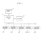
- a management system for carrying out a monitoring method according to one embodiment of the present invention will be described.
- the monitor unit 1 includes a processor, a memory, an input/output circuit, and a keyboard (none of which are shown).
- the injection molding machines A1 to AN manufacture products of the same or different types by repeating molding cycles under the control of a computer numerical control device (not shown).
- Each of these molding machines detects and stores the injection frequency, which is indicative of the molding cycle execution frequency, and at the same time, detects a set of molding process data (cushioning depth, injection time, metering time, metering end position, peak value of injection pressure, screw position for switching from injection speed control to injection pressure control, etc.) for each of the repeatedly executed molding cycles, and stores the set of molding process data for the up-to-date molding cycle.
- a set of molding process data cushioning depth, injection time, metering time, metering end position, peak value of injection pressure, screw position for switching from injection speed control to injection pressure control, etc.
- the monitor unit 1 cyclically detects a set of monitor data indicative of the operating state of each injection molding machine Ai by cyclically fetching the injection frequency and the set of molding process data detected and stored by each molding machine, and successively visually outputs the detected up-to-date monitor data set along with at least a set (e.g., (K - 1) number of sets) of past monitor data.
- K number of sets of up-to-date monitor data for each injection molding machine Ai are renewably stored in the memory of the monitor unit 1.
- the memory of the monitor unit 1 is provided with K number of data tables for storing a set of monitor data for each of first to N'th injection molding machines A1 to AN.
- each of the data tables is loaded with N number of sets of monitor data
- the K number of data tables are loaded with (N ⁇ K) number of sets of monitor data.
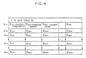
- FIGS. 2, 3 and 4 show a first data table R1 for storing the up-to-date monitor data set, a second data table R2 for storing a past monitor data set detected in a monitor data detection period directly preceding the period for the up-to-date monitor data set, and a K'th data table RK for storing a past monitor data set detected in a monitor data detection period preceding the up-to-date monitor data set by (K - 1) number of cycles, respectively.
- the first to third sub-memory regions are loaded with the injection frequency, cushioning depth, and injection time, respectively.
- the monitor unit 1 selectively calculates (K - 1) number of sets of monitor data variations in accordance with their corresponding ones of K number of monitor data for each injection molding machine Ai, and visually outputs the variations along with the up-to-date and past monitor data, so that the operation records of the injection molding machines A1 to AN can be properly grasped.
- the necessity of the delivery of the monitor data variations is assigned by manual entry by means of the keyboard of the monitor unit 1 or by description in an operation program of the monitor unit 1, and the result of the selection is stored in a flag memory built in the processor.
- a mode in which the monitor data/variations are outputted at predetermined time intervals or a mode (hereinafter referred to as injection frequency mode) in which the monitor data/variations are outputted with every predetermined injection frequency is independently selected for each injection molding machine Ai by manual entry or program description, and the predetermined time intervals or predetermined injection frequencies are set by manual entry or program description.
- the monitor data/variations are printed by means of the printer 2 or displayed on the display screen of the display unit 3. Further, a mode in which the monitor data/variations are printed or a mode in which the monitor data/variations are displayed on the screen is independently selected for each injection molding machine Ai by manual entry or program description. Furthermore, a mode in which the monitor data/variations are printed and displayed on the screen may be provided for selection.
- Each of the injection molding machines A1 to AN executes the molding cycles while detecting and storing the injection frequency and the set of molding process data.
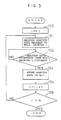
- the processor of the monitor unit cyclically executes a monitor data fetch process shown in Fig. 5.
- the processor sets an index value i stored in its built-in register to "1" which designates the first injection molding machine A1 (Step 100), and delivers a monitor data request signal to the injection molding machine A1 (Step 101).
- the injection molding machine A1 delivers the set of molding process data, detected and stored immediately before the reception of the monitor request signal, to the monitor unit 1.
- the processor of the monitor unit 1 receives the set of molding process data delivered from the injection molding machine A1 as a set of up-to-date monitor data.
- the processor concludes in Step 102 that the reception of the monitor data set is finished, the corresponding monitor data (injection frequency, cushioning depth, injection time, etc.
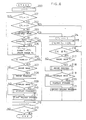
- the processor of the monitor unit 1 While cyclically executing the monitor data described above, the processor of the monitor unit 1 repeatedly executes a monitor data print/display process shown in Fig. 6 in a period shorter than the data fetch process execution period.
- the flag CFi is left reset to the initially set value "0,” so that the result of decision in Step 202 is negative.
- the processor determines whether or not the injection frequency mode is selected for the injection molding machine A1, with reference to the value stored in the corresponding flag memory (Step 203). If the result of this decision is negative, the processor further determines whether or not the time interval mode is selected (Step 204).
- Steps 203 and 204 If neither of the injection frequency mode and the time interval mode is selected, and therefore, it is concluded in Steps 203 and 204 that the monitor data for the first injection molding machine A1 need not be outputted, the processor increments the index value i by "1" to update it in Step 212, and then determines whether or not the total number N of injection molding machines is exceeded by the updated index value i (Step 213). If the result of this decision is negative, the program returns to Step 201.
- CP1 generally, injection frequency CPi for an i'th injection molding machine
- the processor determines whether or not the current injection frequency R111 is not lower than the register value CN1 (Step 216). If the result of this decision is negative, the program returns to Step 201 via Steps 212 and 213. If the injection frequency stored in the injection molding machine at the time of the connection of the injection molding machine to the power supply is reset to "0,” the register CNi is reset to "0" when the monitor unit 1 is connected to the power supply.
- Step 201 When the program returns to Step 201 after the preliminary arrangement for the delivery of the monitor data for the first injection molding machine A1 is finished in this manner, the processor makes preparations for the delivery of the monitor data for the second injection molding machine A2. Likewise, preparations for the third to N'th injection molding machines A3 to AN are made in succession. Then, if it is concluded, in Step 213 immediately after the completion of the preparations for the injection molding machine AN, that the value N is exceeded by the updated index value i , the monitor data print/display process for a first processing period is finished.
- the processor determines whether or not the time measurement or injection frequency measurement is being made with respect to the first injection molding machine A1, which is assigned by setting the index i to the value "1" in Step 200 (Steps 201 and 202). If both the results of decision in these two steps are negative, the results of decision in Steps 203 and 204 are also negative, as is evident from the above description, so that the program proceeds to Step 201 via Steps 212 and 213, whereupon the same discrimination process is started for the second injection molding machine A2.
- Step 201 when the time measurement is being made so that the preset time of the timer T1 is not up, or when the injection frequency measurement is being made so that the register value CN1 is not reached by the current injection frequency R111, it is concluded that the monitor data output timing is not attained, whereupon the program proceeds to Step 201. Thereafter, whether or not the monitor data output timings for the injection molding machines A2 to AN are attained is determined in succession while updating the index value i . If no attainment of the monitor data output timings is discriminated, the monitor data print/display process for the present processing cycle is finished without effecting monitor data print/display.
- the same monitor data print/display process is cyclically executed. If it is concluded that the preset time of the timer Ti associated with any one injection molding machine Ai is up, or that the register value CNi is reached by the current injection frequency Ri11 for the injection molding machine Ai (Step 206 or 216), the processor concludes that the output timing for the monitor data for the i'th injection molding machine Ai is attained, and executes the monitor data print process or monitor data display process.
- the processor determines whether or not a print mode is selected as a monitor data output mode for the i'th injection molding machine Ai, with reference to the corresponding flag memory (Step 207). If the result of this decision is positive, the print process is started (Step 28). In the print process illustrated as a subroutine in Fig. 7, the processor sets an index k to the value "K" to assign the K'th data table RK which is loaded with the oldest or K'th monitor data set (Step SB301), and reads out the K'th monitor data set stored in an i'th memory region Rik of the K'th data table RK, and delivers it to the printer 2 (Step SB302).
- the K'th monitor data set detected in a detection period preceding the detection period for the up-to-date monitor data set for the injection molding machine Ai by (K - 1) number of cycles, is printed by means of the printer 2, as illustrated in Table 1 below.
- the (K - 1)'th monitor data set in the i'th memory region Ri(k-1) of the (K - 1)'th table RK is delivered to the printer 2 to be printed thereby (Step SB303).
- the processor further determines the necessity of the delivery of the monitor data variations for the injection molding machine Ai with reference to the corresponding flag memory (Step SB304).
- the processor calculates the variations of the data of the (K - 1)'th monitor data set with respect to their corresponding data of the K'th monitor data set, and delivers them to the printer 2 (Steps SB305 and SB306). Thereupon, as illustrated in Table 1, a set of monitor data variations are printed on those parts of printing paper which are situated below print regions for the K'th monitor data set and the (K - 1)'th monitor data set.
- Step SB304 After the monitor data variations are printed, or after it is concluded in Step SB304 that the delivery of the monitor data variations is unnecessary, the processor decrements the index k by "1" to update it (Step SB307), and determines whether or not the updated index k is greater than "1.” If the result of this decision is positive, the program returns to Step SB302.
- Steps SB302 to SB308 are repeatedly executed while updating the index k , and (K - 1) number of data groups, each formed of two sets of monitor data (or two sets of monitor data and monitor data variations associated therewith) are printed in succession.
- the index k is decremented to "1" after two sets of up-to-date monitor data (or two sets of up-to-date monitor data and monitor data variations associated therewith) for the injection molding machine Ai are printed, the result of decision in the immediately following step or Step SB308 is negative, and the termination of the print process of Fig. 7 is discriminated. In this case, the program returns to the main routine (monitor data print/display process) of Fig. 6.
- Step 207 the processor further determines whether or not a display mode is selected. If the result of this decision is positive, the program proceeds to the display process illustrated as a subroutine in Fig. 8 (Step 210). As seen from Fig. 8, the display process is executed in the same manner as the print process of Fig. 7. Therefore, a description of the display process is omitted herein. When the termination of the display process is discriminated (SB408), the program returns to the main routine of Fig. 6.
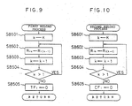
- a first reload process is started to prepare for the next monitor data delivery for the injection molding machine Ai (Step 211).
- the processor sets the data table total number K to the index k (Step SB501), and transfers to and loads the (K - 1)'th monitor data set in the i'th memory region Ri(K-1) of the (K - 1)'th table R(K-1), as a new K'th monitor data set, into the i'th memory region RiK of the K'th data table RK (Step SB502).
- Step SB504 the processor decrements the index k by "1" to update it, and determines whether or not the updated index k is greater than "1" (Step SB504). If the result of this decision is positive, the program returns to Step SB502. Thereafter, Steps SB502 to SB504 are repeatedly executed while decrementing the index k , and the (K - 2)'th to first monitor data sets for the injection molding machine Ai are loaded as new (K - 1)'th to second monitor data sets into the respective i'th memory regions of the data tables R(K-1) to R2, respectively.
- Step 216 If it is concluded in Step 216 that the register value CNi is reached by the current injection frequency Ri11 of any one injection molding machine Ai, while the monitor data print/display process is being cyclically executed, the processor concludes that the output timing for the monitor data for the i'th injection molding machine Ai is attained. In this case, if the processor concludes in Step 217 that the print mode is selected as the monitor data output mode for the injection molding machine Ai, it executes the print process described before with reference to Fig. 7 (Step 218). If the processor concludes in Step 219 that the display mode is selected, it executes the display process mentioned before with reference to Fig. 8 (Step 220). When the print or display process is finished, the processor executes a second reload process (Fig.
- Step 10 which includes Steps SB601 to SB604, identical with Steps SB501 to SB504 of the first reload process mentioned before with reference to Fig. 9, and Step SB605 similar to Step SB505, in which the flag CFi is reset to "0" (Step 221).
- the program proceeds to Step 212. Every time the output timing for the monitor data associated with any one of the injection molding machines A1 to AN is attained in the aforesaid manner, a set of up-to-date monitor data and (K - 1) number of sets of past monitor data for the injection molding machine Ai concerned are visually outputted (printed or displayed on the screen). If necessary, moreover, (K - 1) number of sets of monitor data variations for the injection molding machine Ai are simultaneously outputted. Then, the outputted monitor data sets are reloaded.
- Table 1 shows some of print data for the injection molding machine A1 obtained when the monitor data and monitor data variations are printed with every injection frequency of 1,000 cycles.
- the monitor data variations are calculated by means of the processor every time these variations are outputted.
- a required number of monitor data variation storage tables e.g., K number of tables, may be provided so that two corresponding tables can be referred to when the monitor data variations are outputted.
- the monitor data variations are calculated, in accordance with the up-to-date monitor data and the past monitor data detected in the directly preceding detection period, and loaded into a first table by means of the processor, and the stored monitor data variations are transferred between each adjacent tables, following the steps of procedure described with reference to Fig. 9, every time new monitor data are detected.
- the monitor data/monitor data variations never fail to be printed or displayed on the screen every time the monitor data output timing associated with each injection molding machine is attained.
- the system may be designed so that the monitor data/monitor data variations can be displayed only when a code for assigning a specific injection molding machine is manually inputted through the keyboard of the monitor unit 1 by an operator, in the case where the display mode is selected.
Landscapes
- Engineering & Computer Science (AREA)
- Manufacturing & Machinery (AREA)
- Mechanical Engineering (AREA)
- Human Computer Interaction (AREA)
- Physics & Mathematics (AREA)
- General Physics & Mathematics (AREA)
- Automation & Control Theory (AREA)
- Injection Moulding Of Plastics Or The Like (AREA)
Applications Claiming Priority (3)
| Application Number | Priority Date | Filing Date | Title |
|---|---|---|---|
| JP2157744A JP2673464B2 (ja) | 1990-06-18 | 1990-06-18 | 成形モニタ装置 |
| JP157744/90 | 1990-06-18 | ||
| PCT/JP1991/000761 WO1991019601A1 (en) | 1990-06-18 | 1991-06-05 | Method of monitoring operating conditions of injection molding machine |
Publications (3)
| Publication Number | Publication Date |
|---|---|
| EP0487740A1 EP0487740A1 (en) | 1992-06-03 |
| EP0487740A4 EP0487740A4 (en) | 1992-07-08 |
| EP0487740B1 true EP0487740B1 (en) | 1995-08-23 |
Family
ID=15656404
Family Applications (1)
| Application Number | Title | Priority Date | Filing Date |
|---|---|---|---|
| EP91910448A Expired - Lifetime EP0487740B1 (en) | 1990-06-18 | 1991-06-05 | Method of monitoring operating conditions of injection molding machine |
Country Status (5)
| Country | Link |
|---|---|
| US (1) | US5309369A (ja) |
| EP (1) | EP0487740B1 (ja) |
| JP (1) | JP2673464B2 (ja) |
| DE (1) | DE69112353T2 (ja) |
| WO (1) | WO1991019601A1 (ja) |
Cited By (1)
| Publication number | Priority date | Publication date | Assignee | Title |
|---|---|---|---|---|
| CN105522704A (zh) * | 2014-10-17 | 2016-04-27 | 发那科株式会社 | 注射成型系统 |
Families Citing this family (21)
| Publication number | Priority date | Publication date | Assignee | Title |
|---|---|---|---|---|
| JP2727139B2 (ja) * | 1991-05-18 | 1998-03-11 | ファナック株式会社 | 射出成形機の稼働時間分析装置 |
| EP0603244B1 (de) * | 1991-09-12 | 1997-03-19 | Engel Maschinenbau Gesellschaft m.b.H. | Verfahren zur steuerung einer maschine für die herstellung von produkten, insbesondere zur steuerung einer spritzgiessmaschine |
| JP3050348B2 (ja) * | 1992-04-17 | 2000-06-12 | インターナショナル・ビジネス・マシーンズ・コーポレイション | プロセス制御システムにおけるユーザ制御のための方法と装置 |
| US5817988A (en) * | 1994-08-18 | 1998-10-06 | Sumitomo Wiring Systems, Ltd. | Weight checker for moldings |
| TW311113B (ja) * | 1995-11-02 | 1997-07-21 | Fujitsu Ltd | |
| ATE236000T1 (de) * | 1996-02-02 | 2003-04-15 | Georg Taubmann | Verfahren und anordnung zum verwalten der formen für die maschinelle herstellung von formkörpern aus beton oder artverwandten materialien |
| US5706239A (en) * | 1996-02-27 | 1998-01-06 | Centennial Technologies, Inc. | Rechargeable SRAM/flash PCMCIA card |
| US6408217B1 (en) | 1996-03-12 | 2002-06-18 | Fujitsu Limited | Computer aided design system and three-dimensional design method using the same and storing medium |
| US5870698A (en) * | 1997-05-03 | 1999-02-09 | Atrix International, Inc. | Multi-purpose machine metering/monitoring apparatus |
| DE10052996C2 (de) * | 2000-10-18 | 2003-03-20 | Demag Ergotech Wiehe Gmbh | Spritzgießeinrichtung mit mindestens zwei Steuerungen |
| JP2003191273A (ja) * | 2001-12-27 | 2003-07-08 | Toshiba Mach Co Ltd | 階層構造型射出成形機 |
| JP3717484B2 (ja) * | 2003-03-03 | 2005-11-16 | ファナック株式会社 | 成形情報印字装置 |
| US7534378B2 (en) * | 2004-03-03 | 2009-05-19 | Rexam Prescription Products Inc. | Plastic forming process monitoring and control |
| US20070294040A1 (en) * | 2006-06-16 | 2007-12-20 | Husky Injection Molding Systems Ltd. | Preventative maintenance indicator system |
| US20070294093A1 (en) * | 2006-06-16 | 2007-12-20 | Husky Injection Molding Systems Ltd. | Preventative maintenance system |
| US20110106284A1 (en) * | 2009-11-02 | 2011-05-05 | Mold-Masters (2007) Limited | System for use in performance of injection molding operations |
| US8280544B2 (en) * | 2009-11-02 | 2012-10-02 | Mold Masters (2007) Limited | System for use in performance of injection molding operations |
| US20110106285A1 (en) * | 2009-11-02 | 2011-05-05 | Mold-Masters (2007) Limited | System for use in performance of injection molding operations |
| US11020889B2 (en) * | 2013-09-05 | 2021-06-01 | Husky Injection Molding Systems Ltd. | Method and system for generating, processing and displaying an indicator of performance of an injection molding machine |
| EP3582050B1 (de) * | 2018-06-12 | 2021-04-28 | Siemens Aktiengesellschaft | Verfahren zum analysieren einer ursache mindestens einer abweichung |
| JP7195956B2 (ja) * | 2019-01-31 | 2022-12-26 | 住友重機械工業株式会社 | 表示装置、射出成形機の制御装置、及び射出成形機 |
Family Cites Families (17)
| Publication number | Priority date | Publication date | Assignee | Title |
|---|---|---|---|---|
| DE2129419C3 (de) * | 1971-06-14 | 1981-12-10 | Siemens AG, 1000 Berlin und 8000 München | Steuereinrichtung für Spritzgießmaschinen, insbesondere Kunststoffspritzgießmaschinen |
| JPS59158237A (ja) * | 1983-02-28 | 1984-09-07 | Toshiba Mach Co Ltd | 射出成形機の制御装置 |
| DE3380662D1 (en) * | 1983-05-20 | 1989-11-09 | John Mickowski | Process for monitoring and controlling intermittently working molding and casting devices and apparatus for performing said process |
| JPS60107315A (ja) * | 1983-11-15 | 1985-06-12 | Kimura:Kk | 射出圧力測定方法 |
| JPS61114832A (ja) * | 1984-11-09 | 1986-06-02 | Fanuc Ltd | 工程モニタができる射出成形機 |
| JPS61134218A (ja) * | 1984-12-05 | 1986-06-21 | Shigeru Tsutsumi | 熱可塑性合成樹脂射出成形システムにおけるホツトランナ−の温度制御表示装置 |
| JPS6384914A (ja) * | 1986-09-30 | 1988-04-15 | Mitsubishi Heavy Ind Ltd | 実測値のトレンド表示方法 |
| JPS63111025A (ja) * | 1986-10-30 | 1988-05-16 | Ube Ind Ltd | 射出条件のモニタ方法 |
| JPS63130326A (ja) * | 1986-11-20 | 1988-06-02 | Nissei Plastics Ind Co | 射出成形機の成形条件設定装置 |
| JPH0829555B2 (ja) * | 1986-11-28 | 1996-03-27 | 積水化学工業株式会社 | 射出成形設備の群管理システム |
| JPH0716988B2 (ja) * | 1987-08-28 | 1995-03-01 | 東芝機械株式会社 | 射出成形機制御システム |
| JPH01190424A (ja) * | 1988-01-26 | 1989-07-31 | Fanuc Ltd | 変更された成形条件を印字する射出成形機 |
| JPH0694152B2 (ja) * | 1988-03-28 | 1994-11-24 | 宇部興産株式会社 | モニタデータ記憶方法 |
| GB2224370B (en) * | 1988-11-01 | 1993-08-04 | Toshiba Machine Co Ltd | Input display apparatus |
| JPH02128821A (ja) * | 1988-11-09 | 1990-05-17 | Toshiba Mach Co Ltd | 射出成形機の最適成形条件設定方法および装置 |
| JP2927434B2 (ja) * | 1988-11-25 | 1999-07-28 | ファナック株式会社 | 射出成形機のオンラインai管理システム |
| US5062052B1 (en) * | 1989-06-20 | 1997-11-18 | Cincinnati Milacron Inc | Logic controlled plastic molding machine with programmable operator interface |
-
1990
- 1990-06-18 JP JP2157744A patent/JP2673464B2/ja not_active Expired - Fee Related
-
1991
- 1991-06-05 US US07/829,049 patent/US5309369A/en not_active Expired - Lifetime
- 1991-06-05 WO PCT/JP1991/000761 patent/WO1991019601A1/ja active IP Right Grant
- 1991-06-05 EP EP91910448A patent/EP0487740B1/en not_active Expired - Lifetime
- 1991-06-05 DE DE69112353T patent/DE69112353T2/de not_active Expired - Fee Related
Non-Patent Citations (3)
| Title |
|---|
| JP-A-1 244 818 (UBE IND LTD) 29 September 1989 & PATENT ABSTRACTS OF JAPAN vol.13, no. 582 (M-911)(3930) 21 December 1989 * |
| JP-A2 128 821 (TOSHIBA MACH CO LTD) 17 May 1990 & PATENT ABSTRACTS OF JAPAN vol. 14, no. 361 (M-1006)(4304) 6 August 1990 * |
| JP-A-63 135 223 (SEKISUI CHEM CO LTD) & PATENT ABSTRACTS OF JAPAN VOL. 12, NO. 384 (M-753)(3231) 13 OCTOBER 1988 * |
Cited By (2)
| Publication number | Priority date | Publication date | Assignee | Title |
|---|---|---|---|---|
| CN105522704A (zh) * | 2014-10-17 | 2016-04-27 | 发那科株式会社 | 注射成型系统 |
| CN105522704B (zh) * | 2014-10-17 | 2017-12-26 | 发那科株式会社 | 注射成型系统 |
Also Published As
| Publication number | Publication date |
|---|---|
| EP0487740A1 (en) | 1992-06-03 |
| JP2673464B2 (ja) | 1997-11-05 |
| EP0487740A4 (en) | 1992-07-08 |
| WO1991019601A1 (en) | 1991-12-26 |
| JPH0449020A (ja) | 1992-02-18 |
| DE69112353T2 (de) | 1996-02-08 |
| DE69112353D1 (de) | 1995-09-28 |
| US5309369A (en) | 1994-05-03 |
Similar Documents
| Publication | Publication Date | Title |
|---|---|---|
| EP0487740B1 (en) | Method of monitoring operating conditions of injection molding machine | |
| EP0737560B1 (en) | Method of analyzing factors influential in product quality of injection molding machine and method of adjusting molding conditions | |
| EP0201606B1 (en) | Injection molding machine capable of monitoring molding process | |
| US7349747B2 (en) | Monitoring device and monitoring method for injection molding machine | |
| EP1020279B1 (en) | Power consumption display device for machine | |
| US4669040A (en) | Self-tuning controller | |
| JP3830453B2 (ja) | 射出成形機のモニタ装置 | |
| US4736324A (en) | Centralized control method for loom and device thereof | |
| US6308141B1 (en) | Method of and apparatus for analyzing alarms of an injection molding machine | |
| CN1312547C (zh) | 数值控制装置 | |
| WO1997029898A1 (fr) | Procede de collecte de donnees de moulage pour machines de moulage par injection et procede pour obtenir une condition de moulage | |
| EP0026326A1 (en) | Timing interval generators and method of generation | |
| EP0623860B1 (en) | Processing finish time predicting numerical control apparatus | |
| KR960016033B1 (ko) | 사출성형기에 있어서의 제품 양부 판별 방법 | |
| WO2002024996A1 (fr) | Systeme d'assistance au tricotage destine a des produits tricotes et systeme serveur d'assistance au tricotage | |
| EP0180429B1 (en) | Combinational weighing system | |
| KR960016032B1 (ko) | 사출성형기에 있어서의 성형 조건 설정 방법 | |
| JPH06186065A (ja) | プロセスデータの表示方法及び装置 | |
| JPS5835605A (ja) | 計測制御装置 | |
| JP3661732B2 (ja) | プログラマブルコントローラ | |
| JP2963676B2 (ja) | プログラマブルコントローラ | |
| JPS6384914A (ja) | 実測値のトレンド表示方法 | |
| US5500809A (en) | Microcomputer system provided with mechanism for controlling operation of program | |
| JP3971317B2 (ja) | 成形機の制御方法 | |
| JPH0733052B2 (ja) | プラスチック押出成形ラインにおけるデータ分析装置 |
Legal Events
| Date | Code | Title | Description |
|---|---|---|---|
| PUAI | Public reference made under article 153(3) epc to a published international application that has entered the european phase |
Free format text: ORIGINAL CODE: 0009012 |
|
| 17P | Request for examination filed |
Effective date: 19920310 |
|
| AK | Designated contracting states |
Kind code of ref document: A1 Designated state(s): CH DE IT LI |
|
| A4 | Supplementary search report drawn up and despatched |
Effective date: 19920514 |
|
| AK | Designated contracting states |
Kind code of ref document: A4 Designated state(s): CH DE IT LI |
|
| 17Q | First examination report despatched |
Effective date: 19940310 |
|
| GRAA | (expected) grant |
Free format text: ORIGINAL CODE: 0009210 |
|
| AK | Designated contracting states |
Kind code of ref document: B1 Designated state(s): CH DE IT LI |
|
| REF | Corresponds to: |
Ref document number: 69112353 Country of ref document: DE Date of ref document: 19950928 |
|
| ITF | It: translation for a ep patent filed |
Owner name: ING. ZINI MARANESI & C. S.R.L. |
|
| PLBE | No opposition filed within time limit |
Free format text: ORIGINAL CODE: 0009261 |
|
| STAA | Information on the status of an ep patent application or granted ep patent |
Free format text: STATUS: NO OPPOSITION FILED WITHIN TIME LIMIT |
|
| 26N | No opposition filed | ||
| PGFP | Annual fee paid to national office [announced via postgrant information from national office to epo] |
Ref country code: CH Payment date: 20000613 Year of fee payment: 10 |
|
| PG25 | Lapsed in a contracting state [announced via postgrant information from national office to epo] |
Ref country code: LI Free format text: LAPSE BECAUSE OF NON-PAYMENT OF DUE FEES Effective date: 20010630 Ref country code: CH Free format text: LAPSE BECAUSE OF NON-PAYMENT OF DUE FEES Effective date: 20010630 |
|
| REG | Reference to a national code |
Ref country code: CH Ref legal event code: PL |
|
| PG25 | Lapsed in a contracting state [announced via postgrant information from national office to epo] |
Ref country code: IT Free format text: LAPSE BECAUSE OF NON-PAYMENT OF DUE FEES;WARNING: LAPSES OF ITALIAN PATENTS WITH EFFECTIVE DATE BEFORE 2007 MAY HAVE OCCURRED AT ANY TIME BEFORE 2007. THE CORRECT EFFECTIVE DATE MAY BE DIFFERENT FROM THE ONE RECORDED. Effective date: 20050605 |
|
| PGFP | Annual fee paid to national office [announced via postgrant information from national office to epo] |
Ref country code: DE Payment date: 20080612 Year of fee payment: 18 |
|
| PG25 | Lapsed in a contracting state [announced via postgrant information from national office to epo] |
Ref country code: DE Free format text: LAPSE BECAUSE OF NON-PAYMENT OF DUE FEES Effective date: 20100101 |