EP0487002B1 - Dispositif de climatisation de l'habitacle d'un véhicule automobile - Google Patents
Dispositif de climatisation de l'habitacle d'un véhicule automobile Download PDFInfo
- Publication number
- EP0487002B1 EP0487002B1 EP91119660A EP91119660A EP0487002B1 EP 0487002 B1 EP0487002 B1 EP 0487002B1 EP 91119660 A EP91119660 A EP 91119660A EP 91119660 A EP91119660 A EP 91119660A EP 0487002 B1 EP0487002 B1 EP 0487002B1
- Authority
- EP
- European Patent Office
- Prior art keywords
- ejector
- refrigerant
- inlet
- pressure
- outlet
- Prior art date
- Legal status (The legal status is an assumption and is not a legal conclusion. Google has not performed a legal analysis and makes no representation as to the accuracy of the status listed.)
- Expired - Lifetime
Links
Images

Classifications
-
- F—MECHANICAL ENGINEERING; LIGHTING; HEATING; WEAPONS; BLASTING
- F25—REFRIGERATION OR COOLING; COMBINED HEATING AND REFRIGERATION SYSTEMS; HEAT PUMP SYSTEMS; MANUFACTURE OR STORAGE OF ICE; LIQUEFACTION SOLIDIFICATION OF GASES
- F25B—REFRIGERATION MACHINES, PLANTS OR SYSTEMS; COMBINED HEATING AND REFRIGERATION SYSTEMS; HEAT PUMP SYSTEMS
- F25B41/00—Fluid-circulation arrangements
-
- B—PERFORMING OPERATIONS; TRANSPORTING
- B60—VEHICLES IN GENERAL
- B60H—ARRANGEMENTS OF HEATING, COOLING, VENTILATING OR OTHER AIR-TREATING DEVICES SPECIALLY ADAPTED FOR PASSENGER OR GOODS SPACES OF VEHICLES
- B60H1/00—Heating, cooling or ventilating [HVAC] devices
- B60H1/32—Cooling devices
- B60H1/3204—Cooling devices using compression
-
- F—MECHANICAL ENGINEERING; LIGHTING; HEATING; WEAPONS; BLASTING
- F25—REFRIGERATION OR COOLING; COMBINED HEATING AND REFRIGERATION SYSTEMS; HEAT PUMP SYSTEMS; MANUFACTURE OR STORAGE OF ICE; LIQUEFACTION SOLIDIFICATION OF GASES
- F25B—REFRIGERATION MACHINES, PLANTS OR SYSTEMS; COMBINED HEATING AND REFRIGERATION SYSTEMS; HEAT PUMP SYSTEMS
- F25B1/00—Compression machines, plants or systems with non-reversible cycle
- F25B1/06—Compression machines, plants or systems with non-reversible cycle with compressor of jet type, e.g. using liquid under pressure
-
- B—PERFORMING OPERATIONS; TRANSPORTING
- B60—VEHICLES IN GENERAL
- B60H—ARRANGEMENTS OF HEATING, COOLING, VENTILATING OR OTHER AIR-TREATING DEVICES SPECIALLY ADAPTED FOR PASSENGER OR GOODS SPACES OF VEHICLES
- B60H1/00—Heating, cooling or ventilating [HVAC] devices
- B60H1/32—Cooling devices
- B60H2001/3286—Constructional features
- B60H2001/3298—Ejector-type refrigerant circuits
-
- F—MECHANICAL ENGINEERING; LIGHTING; HEATING; WEAPONS; BLASTING
- F25—REFRIGERATION OR COOLING; COMBINED HEATING AND REFRIGERATION SYSTEMS; HEAT PUMP SYSTEMS; MANUFACTURE OR STORAGE OF ICE; LIQUEFACTION SOLIDIFICATION OF GASES
- F25B—REFRIGERATION MACHINES, PLANTS OR SYSTEMS; COMBINED HEATING AND REFRIGERATION SYSTEMS; HEAT PUMP SYSTEMS
- F25B2341/00—Details of ejectors not being used as compression device; Details of flow restrictors or expansion valves
- F25B2341/001—Ejectors not being used as compression device
- F25B2341/0012—Ejectors with the cooled primary flow at high pressure
-
- F—MECHANICAL ENGINEERING; LIGHTING; HEATING; WEAPONS; BLASTING
- F25—REFRIGERATION OR COOLING; COMBINED HEATING AND REFRIGERATION SYSTEMS; HEAT PUMP SYSTEMS; MANUFACTURE OR STORAGE OF ICE; LIQUEFACTION SOLIDIFICATION OF GASES
- F25B—REFRIGERATION MACHINES, PLANTS OR SYSTEMS; COMBINED HEATING AND REFRIGERATION SYSTEMS; HEAT PUMP SYSTEMS
- F25B2400/00—General features or devices for refrigeration machines, plants or systems, combined heating and refrigeration systems or heat-pump systems, i.e. not limited to a particular subgroup of F25B
- F25B2400/23—Separators
-
- F—MECHANICAL ENGINEERING; LIGHTING; HEATING; WEAPONS; BLASTING
- F25—REFRIGERATION OR COOLING; COMBINED HEATING AND REFRIGERATION SYSTEMS; HEAT PUMP SYSTEMS; MANUFACTURE OR STORAGE OF ICE; LIQUEFACTION SOLIDIFICATION OF GASES
- F25B—REFRIGERATION MACHINES, PLANTS OR SYSTEMS; COMBINED HEATING AND REFRIGERATION SYSTEMS; HEAT PUMP SYSTEMS
- F25B2500/00—Problems to be solved
- F25B2500/01—Geometry problems, e.g. for reducing size
-
- F—MECHANICAL ENGINEERING; LIGHTING; HEATING; WEAPONS; BLASTING
- F25—REFRIGERATION OR COOLING; COMBINED HEATING AND REFRIGERATION SYSTEMS; HEAT PUMP SYSTEMS; MANUFACTURE OR STORAGE OF ICE; LIQUEFACTION SOLIDIFICATION OF GASES
- F25B—REFRIGERATION MACHINES, PLANTS OR SYSTEMS; COMBINED HEATING AND REFRIGERATION SYSTEMS; HEAT PUMP SYSTEMS
- F25B2500/00—Problems to be solved
- F25B2500/18—Optimization, e.g. high integration of refrigeration components
Definitions
- the invention relates to a device for air conditioning the interior of motor vehicles.
- a thermostatic injection valve 2 feeds the refrigerant to the evaporator 4 in such a controlled manner that it always exits the evaporator 4 when overheated.
- the superheated refrigerant is drawn in by the compressor (also called a compressor) 6, compressed and then fed to the condenser (also called the condenser) 8 under higher pressure, in which it is liquefied.
- the liquefied refrigerant is then fed from the liquefier 8 to a collecting container 10 which contains a buffer amount of liquid refrigerant as a reserve and in which a filter dryer can be integrated.
- the collection container 10 then serves in a closed circuit for supplying the injection valve 2 with liquid refrigerant.
- this known circuit Due to the thermostatic, i.e. Temperature-dependent, control of the injection valve 2 to optimal outlet conditions of the refrigerant on the evaporator 4, this known circuit is not only suitable for full load, but also for partial load conditions. It dominates in Europe (approx. 70% market share).
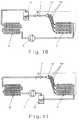
- the thermostatic injection valve 2 is replaced by a fixed throttle 2a which, compared to the thermostatic injection valve 2 of FIG. 10, has the advantage of being around a power of ten lower Has costs.
- This refrigerant cycle is particularly common in the United States; in line with the corresponding English-speaking term of the fixed choke 2a, this is also called English in the German-speaking area, namely "fix orifice".
- Such a fixed throttle 2a can only ever be designed for a certain load state of the evaporator 4, usually in such a way that full load can still be driven. At partial load, the fixed throttle 2a still allows too much refrigerant to pass through, which is then no longer evaporated in the evaporator 4.
- the collecting container 10 is now, instead of as in the case of FIG. 10 on the high pressure side, now according to FIG. 11 on the low pressure side between the outlet of the evaporator 4 and the Input of the compressor 6 arranged.
- the refrigerant is not compressed to such an extent that the collecting container in the arrangement according to FIG. 11 must be dimensioned larger than in the arrangement according to FIG. 10, whereby part of the reduction in price , but not the entire discount, the replacement of the thermostatically controlled injection valve 2 by the fixed throttle 2a is consumed.
- FIG. 11 has a somewhat lower output in relation to that of FIG. 10 in the partial load range. If the refrigerant circuits according to FIGS. 10 and 11 were each designed for the same output, the refrigerant circuit according to FIG. 11 would therefore require somewhat more drive power for the compressor 6, more generally speaking, more energy supplied and thus practically more fuel consumption with a mechanically simpler structure.
- This refrigerant circuit according to FIG. 11 has the same or even a higher market share for motor vehicles manufactured in the USA as the refrigerant circuit according to FIG. 10 in Europe. A printed proof of the refrigerant circuit according to FIG. 11 is currently not available for the applicant.
- the refrigerant is in front of the evaporator 4 in two phases, ie as a mixture of the liquid and gaseous phases.
- This requires mechanically relatively complex distribution devices 12 for the uniform division of this phase mixture without segregation into individual refrigerant circuit paths 4a connected in parallel in the evaporator 4.
- the distribution devices are mostly turned parts with soldered supply capillaries. These distributors are difficult to manufacture and relatively expensive.
- the invention is based on the object, in a device for air conditioning the interior of motor vehicles, not only for a single load range as in the case of FIG. 10, but for all the load ranges in question, a throttling member of simple mechanical construction without need for control as in the case of FIG To be able to use 10 without having to accept losses in performance, the aim being to also open up the possibility, through the new design, of being able to construct the distribution devices 12 more mechanically.
- the invention is based on the refrigerant circuit according to FIG. 11, in which the collecting container 10 is already arranged on the low pressure side.
- the achievement of the object on which the invention is based results from the characterizing features of claim 1.
- An ejector is structurally less expensive than the fixed throttle 2a according to FIG. 10 and significantly less expensive than the thermostatically controlled one Injection valve 2 according to FIG. 10.
- there is no longer a lossy swirling of the refrigerant but, in any case ideally, a relaxation of the refrigerant with constant entropy, so that the enthalpy decreases during the throttling process in the ejector and thus the available enthalpy absorption per kilogram of refrigerant in the evaporator increases.
- the refrigerant circuit according to the invention further has the effect that, with the same power of the evaporator, i.e. at the same evaporation temperature and thus the same saturation pressure in the evaporator, the suction pressure for the compressor in the device according to the invention is approximately 0.5 bar higher than in the known refrigerant circuits of FIG. 10 and 11.
- This increase in pressure also increases the density of the drawn-in refrigerant and ultimately the mass flow in the entire circuit. This results in an increase in performance with the same energy supply or with the same predetermined performance data, a saving in supplied energy, in particular in fuel used for the operation of air conditioning circuits.
- ejectors For applications other than air conditioning of the interior of motor vehicles, ejectors have long been widespread without having found their way into the air conditioning of the interior of motor vehicles according to the effects described. For example, ejectors have been used in jet chillers for steam or other refrigerants.
- FIGS. 10 and 11 Another cooling circuit deviating from the arrangement according to FIGS. 10 and 11, which is provided for the stationary air conditioning technology, is from the document Heating / Piping / Air Conditioning Vol. 47, No. 8, August 1975, pp. 56 to 59.
- the characterizing feature a) of claim 1 In contrast to the refrigerant circuit according to FIGS. 10 or 11, the refrigerant emerging from the condenser is accelerated to supersonic speed in a propulsion jet nozzle of an ejector and thereby relaxed. The pressure reduction in the low-pressure part of the ejector caused by the high jet speed is used to extract the refrigerant from a refrigerant / water evaporator device.
- the speed of the refrigerant sucked out of the evaporator and the driving jet speed are adjusted in the middle part of the ejector by impulse compensation.
- a large part of the dynamic energy is converted back into static pressure by a diffuser formed on the outlet side in the ejector, so that the suction pressure of the compressor is higher than the pressure in the evaporator.
- the refrigerant flow is divided into a liquid phase, which is returned to the evaporator, and a gaseous phase, which is drawn off by the compressor.
- the pressure increase achieved in the ejector improves the performance and efficiency of the compressor and on the other hand enables the liquid phase separated in the separator to be returned to the evaporator.
- the pressure increase in the ejector serves to overcome the flow pressure losses.
- a refrigerant circuit according to this device which is known per se for stationary and in particular heavy-weight systems, therefore has the advantage in comparison with the circuits known for motor vehicle air conditioning systems according to FIGS. 10 and 11 that part of the energy lost during the throttling process in the fixed throttle or in the expansion valve the ejector is converted into a pressure increase and that the evaporator is charged with liquid single-phase refrigerant via the phase separator.
- Ejectors are inherently part of the designer's tool for propellant pumps.
- a rapidly moving liquid, gas or steam jet of high density serves as the working medium, which is introduced through the high pressure inlet of the ejector into its nozzle.
- the propellant mixes with gas supplied via the low-pressure inlet, which envelops the jet emerging from the ejector nozzle.
- the speeds of the two components introduced from the high-pressure inlet and the low-pressure inlet into the ejector are equalized by pulse exchange (see, for example, specialist dictionary ABC Physik, publishers Harry Deutsch, Zurich and Frankfurt am Main, vol. 1, 1974, p. 338, keyword "ejector ").
- Laval nozzle keyword "Laval nozzle”
- the use of a Laval nozzle in the ejector for single-phase inlet of the refrigerant from the high-pressure inlet of the ejector to the throttle cross-section of the nozzle is provided in order to achieve a jet of propellant that is as well concentrated as possible, so that the pressure is converted into speed energy to the maximum.
- the exit angle for single-phase blowing agent can be calculated exactly.
- the outlet angle of the nozzle behind the throttle cross-section is formed with a larger opening angle than with a Laval nozzle for single-phase inlet. This results in an adaptation of the nozzle cross section to the decreasing density of the propellant jet emerging from the throttle cross section. It has been shown that ejectors for circuits according to the invention can be designed with minimal throttle cross sections of their nozzle, which are generally of the same size or slightly larger than fixed throttles according to throttles 2a of FIG. 11.
- the known arrangement of a filter drier in the collector is expediently taken over in the direction of flow before its outlet for the liquid phase, which was not previously provided.
- an arrangement of a filter dryer is critical because of the gaseous component which is always present in the flow area, within the scope of the invention this filter dryer can be very conveniently arranged in the area through which the liquid phase flows. This provides corrosion protection for the use of elastic pipe material that is customary for refrigerant pipes in air conditioning systems of motor vehicles.
- Claims 2 and 3 indicate particularly simple construction methods of an ejector that can be used in the device according to the invention.
- one can 10 and 11 in the context of the invention completely dispense with complicated distribution devices 12 and replace them with simple throttle orifices, which in the preferred limit case may even be simply wall bores of the inlet-side header pipe (distribution pipe) of the evaporator.
- the device according to the invention has been specially developed for air conditioning the interior of motor vehicles. However, it is not excluded that a device with the features of the invention could also be used for stationary air conditioning purposes.
- the evaporation temperatures in the evaporator are approximately in the range between -10 ° C and + 10 ° C, at lower evaporation temperatures, in particular approximately in the case of evaporation temperatures in the range between -30 ° C and -40 ° C, one can still achieve significantly higher efficiency improvements come because the ratio of condensing pressure to evaporation pressure is greater. This also opens up a useful secondary benefit the manufacture of devices according to the invention for use in stationary air conditioning applications, for example in cold stores.
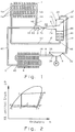
- the ejector 20 replaces the fixed throttle 2a in FIG. 11.
- the refrigerant emerging from the ejector 20 in the direction of the arrow 22 indicating the circulating medium flow through the outlet 24 of the ejector 20 is fed into the collector 10 through the inlet 26 thereof supplied, namely in a region of the collecting container 10, in which there is always at least a portion of the gaseous phase. It is possible, in the manner shown, to connect the outlet 24 of the ejector 20 and the inlet 26 of the collecting container 10 directly to one another, or even to build them up in a common structural unit. But you can also provide a line adapter, which, however, is chosen to be relatively short.
- the outlet 28 for the gaseous phase of the collecting container 10 is connected via a connecting line 30 to the inlet 32 of the compressor 6, which has a drive from the vehicle engine M.
- the connecting line 30 is usually designed as a hose line.
- Its output 40 is via a connecting line 42, e.g. Made of aluminum or an aluminum alloy, connected to the high pressure inlet 44 of the ejector 20.
- the collecting container 10 is provided with an additional outlet 46 for the liquid phase of the refrigerant, which is collected in the liquid phase in the lower region of the collecting container. While this collection only represents a discontinued intermediate buffer in the known arrangements of FIGS. 10 and 11, it is included here in the flow circuit through the outlet 46 of the collecting container 10.
- baffles 50 are also arranged from the two opposite upright walls nested against each other, on which are still in the gaseous stream can remove entrained liquid particles to drip off.
- the output 46 of the collecting container 10 is connected via a rigid or hose-like connecting line 52 to an input collector 54 of the evaporator 4, which here is formed with three refrigeration circuit paths 4a connected in parallel. In practice, one to four such routes are possible.
- the refrigeration cycle paths open into an output collector 56, which is connected to the low-pressure inlet 60 of the ejector 20 via a connecting line 58.
- reference locations A to F are also entered, which correspond to the state points of the state diagram according to FIG. 2, which will be described further below.
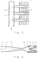
- FIG. 3 A possible embodiment of the ejector is also described with reference to FIG. 3 to illustrate its essential components.
- the high-pressure inlet 44 of the ejector 20 is designed with a gradation as a solder connection for the feed line 42.
- From High-pressure outlet 44 from the axially straight flow cross section in the form of an inlet nozzle 62 narrows to a minimal throttle cross section 64, the clear width of which is equal to or somewhat larger than the throttle bore of the fixed throttle 2a in FIG. 10.
- the nozzle channel extends as a (first) diffuser 66, from which a jet of propellant of the propellant that has entered the high-pressure inlet 44 flows freely axially through the mixing chamber 68.
- the low-pressure inlet which is connected to an annular space 70 surrounding the arrangement of the nozzle, is arranged in the ejector 20 to the side of the nozzle 62, 64, 66. From there, the gaseous refrigerant fed into the low-pressure inlet 60 enters the mixing chamber 68 as an enveloping flow around the core flow emerging from the diffuser 66, where mixing takes place with impulse adjustment without swirling. Again axially aligned with the other elements 44, 62, 64, 66 and 68, the mixing chamber 68 is followed by a second diffuser 72, the outlet 24 of which, like the high-pressure inlet 44, is designed as a solder connection. The relative proportions are approximately to scale as indicated in FIG. 3.
- the low-pressure inlet 60 is also designed as a solder connection.
- its diffuser 66 is designed in the form of the entire nozzle as a Laval nozzle, which means that in particular the opening angle of the diffuser 66 is determined.
- This embodiment is intended for the case in which only coolant in the liquid phase is present upstream of the throttle orifice 64. However, if the coolant present, which is supplied via the high-pressure inlet 44, gives rise to gaseous component inside the inlet nozzle 62 in front of the throttle cross-section 64, the opening angle of the diffuser 66 is chosen to be wider than in the case of a Laval nozzle.
- a scale is formed over the length of the ejector 20, the abscissa of which corresponds to the axial flow path in the ejector and on whose ordinate is the refrigerant pressure in the ejector 20.
- the vertical dashed lines are merely imaginary assignment lines to the corresponding locations of the ejector 20 in FIG. 3.
- the pressure curve in FIG. 4 corresponds to the pressure curve of the refrigerant supplied to the ejector 20 through the high-pressure inlet 44 and which is in the nozzle 62, 64, 66 is relaxed.
- the pressure curve on the part of the low pressure inlet 60 is shown in dash-dot lines.
- the ejector can simply be composed of two components 74 and 76, which are sealed against one another by an O-ring seal 78. While both components 74 and 76 are machined components in the embodiment according to FIG. 3, this only applies to the first component 74 in the variant according to FIG. 6, while the second component 76 is simply part of the continuous pipe routing, which is the second diffuser 72 is formed without cutting, for example by rolling, pressing, pressing etc.
- FIG. 5 shows how particularly easily the distribution of the refrigerant from the inlet manifold 54 of the evaporator 4, which serves as its inlet, to the individual (here three) refrigerant circuit paths 4a, namely simply through wall bores 80 with the diameter d acting as perforated shutters in the wall of the input collector 54.
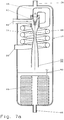
- FIG. 7 shows, as a second embodiment, a variant of the coolant circuit according to FIG. 1, in which all the elements not described again below for the sake of simplicity correspond to those of FIG. 1.
- the special feature is the following:
- the connecting line 42 from the outlet 40 of the condenser 8 to the high-pressure inlet 44 of the ejector 20 is here in the vicinity of the connecting line 30 between the outlet 28 for the gaseous phase of the collector 10 and the inlet 32 of the compressor 6, the two connecting lines 42 and 30 than the two flow paths of an additional heat exchanger 82 are incorporated therein. As a result, the connecting line 30 is warmed up from the connecting line 42 with the effect described earlier.
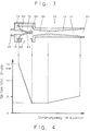
- the housing of the collecting container 10 initially has the outlet 28 for the gaseous phase and the outlet 46 for the liquid phase on the upper and lower end faces.
- the output of the ejector is no longer connected by a separate connection to a separate inlet of the collecting container 10 in its space for the gaseous phase, but this connection is realized indirectly.
- the ejector 20 is namely received axially below the outlet 28 for the gaseous phase in its receiving space within the collecting container 10 so that the outlet 24 of the ejector also forms the entrance 26 of the collecting container 10.
- the separate material input 26 of the collecting container 10 according to FIGS. 1 and 7 is here virtually divided into two inputs 84 and 86, so that the collecting container has four wall connections 28, 46, 84 and 86 as a whole.
- the wall connection 84 is designed as a soldered connection and is used to connect the connecting line 58 which, according to FIG. 1, leads from the output manifold 56 of the evaporator 4 to the low-pressure inlet 60 of the ejector 20, but now, unlike in FIGS. 1 and 7, not outside but inside of the collecting container 10 ending.
- the input 86 which can also be formed again as a soldered connection, is connected to the line 42, which here extends further into the interior of the collecting space taken up by the gaseous phase of the collecting space and thereby merges into a pipe coil 88 which is smooth or ribbed heat exchange tube is used and surrounds the ejector 20.
- the pipe coil 88 leads from the inlet 86 to the high pressure inlet 44 of the ejector 20. In this arrangement, the pipe coil 88 has the same effect as the inner heat exchanger 82 according to FIG. 7.
- the liquid level in the collecting container 10 which separates its lower space occupied by liquid from its upper space largely occupied by the gaseous phase, is designated by 90.
- FIG. 7 like in FIG. 1, identification letters are additionally introduced, which represent a spatial assignment of operating phases of the diagram according to FIG. 8 relating to FIG. 7. 8 is discussed later, as is FIG. 2.
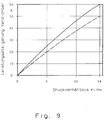
- the pressure ratio p C / p O is plotted as the abscissa, p C indicating the pressure at the inlet of the condenser 8 and p O the pressure at the outlet of the evaporator 4.
- the performance increases on the compressor 6 that can be achieved according to the invention with the circuits of the invention according to FIGS. 1 or 7 are given here in percentages for various conventional refrigerants.
- the solid curve relates to the refrigerant R 12 or the refrigerant R 134a and the dashed curve relates to the refrigerant R 22.
- the refrigerant R 12 is a refrigerant that is currently expiring for environmental reasons and is based on a chlorofluorocarbon, CFC for short, which is currently being replaced by the less environmentally harmful refrigerant R 134a based on a hydrogen fluorocarbon HFC.
- the names of these safety refrigerants correspond to the international standard.
- the mixing chamber 68 of the ejector 20 already forms the inlet cone of the second diffuser 72 and serves as a collecting nozzle for the core jet emerging from the first diffuser 66, which comes from the high-pressure inlet 44 of the ejector 20.
- the refrigerant states before and after the circuit components shown in FIG. 1 are evaporator 4, condenser 8, compressor 6, ejector 20, collecting container 10 in the Mollier-hlgp diagram with the enthalpy h as the abscissa and the refrigerant pressure p in a log mixer Represented as ordinate.
- the correspondence for the individual status points of FIG. 2 correlate with the printing letters also drawn in FIG. 1.
- the compressor 6 sucks the saturated gas with state A ′′ from the collecting container 10 and compresses it to the condensing pressure with state point B.
- the condenser 8 the refrigerant is liquefied with a drop in pressure and decrease in enthalpy and emerges with a slight supercooling of 1-10 K. the condenser with state C.
- the refrigerant is throttled from the state point C to the evaporation pressure according to the state point D with a simultaneous increase in the dynamic energy.
- Gaseous refrigerant with state F is now sucked out of the evaporator 4 in the mixing chamber 68 and mixed with the liquid jet from the first diffuser 66 while exchanging impulses.
- the speed energy is largely converted back into a static pressure increase, so that at the end of the second diffuser 72 the common state E is reached with a pressure that is about 0.5 bar higher than in the evaporator 4.
- the collecting container 10 there is now a phase separation at constant pressure into a gaseous phase A ′′, which, as already described, is sucked off by the compressor 6, and into a liquid phase A ', which is fed via a filter dryer 48 to the input collector 54 of the evaporator 4 and is throttled there from the state A' to the state G through the wall bores 80.
- This additional pressure loss between the state points A 'and G serves for the uniform distribution of the liquid refrigerant in the individual refrigeration cycle paths 4a.
- FIG. 8 the refrigerant condition points of FIG. 7 are drawn in the Mollier-hlgp diagram already described, analogously to FIG. 2.
- the condition points marked with large block letters apply to the point in the refrigeration cycle shown in FIG. 7 with the same letters.
- the refrigerant circuit is unchanged from FIG. 2, so that only the changes in the states in the inner heat exchanger 82 are described.
- the refrigerant emerges as a saturated vapor with state A ′′ from the collecting container 10 and is brought into heat exchange in the inner heat exchanger 82 with the connecting line 42 between the condenser 8 and the ejector 20. This results in an increase in temperature and enthalpy at constant pressure to state point A '''.
- the strongly overheated condition ensures that there are no longer any liquid droplets in the gaseous refrigerant, which evaporate in the connecting line 30 between the collecting container 10 and the compressor 6 and in the compressor 6 itself while absorbing ambient heat from the engine compartment and thus unnecessarily burden the refrigerant circuit . Due to the higher temperature and enthalpy of the refrigerant drawn in by the compressor 6, the refrigerant also shifts State point B 'after the compressor 6 at the same pressure also to higher final compression temperatures and higher enthalpy. For this reason, the internal heat exchanger 82 must not be dimensioned so high in performance that impermissibly high final compression temperatures arise.
- the refrigerant is now liquefied to the state point C, as in FIG. 2, and further subcooled to the state point C ′ by the heat exchange in the inner heat exchanger 82 at constant pressure.
Landscapes
- Engineering & Computer Science (AREA)
- Physics & Mathematics (AREA)
- Thermal Sciences (AREA)
- Mechanical Engineering (AREA)
- General Engineering & Computer Science (AREA)
- Air-Conditioning For Vehicles (AREA)
Claims (7)
- Dispositif pour la climatisation de l'habitacle de véhicules motorisés, comportant un circuit de réfrigérant qui est constitué d'une partie basse pression et d'une partie haute pression, dans le cas duquel un réfrigérant, sortant d'un évaporateur (4) en phase vapeur et passant par un collecteur (10) qui agit comme séparateur de phase entre la phase liquide et la phase gazeuse, est extrait par un compresseur (6), par une sortie (28) pour la phase gazeuse et est amené, avec élévation de la pression, à un condenseur (8) pour refroidissement et condensation et dans le cas duquel du réfrigérant sortant du condenseur (8) en phase liquide peut être renvoyé dans l'évaporateur (4), en passant par un élément d'étranglement (20), avec diminution de pression et refroidissement,
caractérisé par la combinaison de caractéristiques suivantes:a) l'élément d'étranglement est conçu en tant qu'éjecteur (20) dont l'entrée haute pression (4) est reliée à la sortie (40) du condenseur (8) et dont l'entrée basse pression (30) est reliée à la sortie (56) de l'évaporateur (4);b) la sortie (24) de l'éjecteur (20) est reliée à l'entrée (26) du collecteur (10) ou forme ce collecteur, le collecteur (10) étant muni, pour la phase liquide, d'une sortie (46) qui est reliée à l'entrée (54) de l'évaporateur (4);c) pour le passage, en phase unique, du réfrigérant, de l'entrée haute pression (44) de l'éjecteur (20) jusqu'à la section d'étranglement (64) de la buse, celle-ci est conçue en tant que buse de Laval, tandis que pour les conditions de passage du réfrigérant entre l'entrée haute pression (44) de l'éjecteur (20) et la section d'étranglement (64) de la buse, dans lesquelles, en avant de la section d'étranglement (64) dans le sens de l'écoulement (22), une partie du réfrigérant se convertit déjà en la phase gazeuse, l'angle de sortie de la buse derrière la section d'étranglement (64) possède un angle d'ouverture plus grand que dans le cas d'une buse de Laval;d) dans le collecteur (10), en avant, dans le sens de l'écoulement, de sa sortie (46) pour la phase liquide est disposé un sécheur filtrant (48). - Dispositif selon la revendication 1, caractérisé par le fait que l'éjecteur (20) est conçu en deux parties, la première partie (74) formant sa buse et la seconde partie (76) étant un morceau de tube mis en forme, avec formation de la chambre de mélange (68) et du (second) diffuseur ((72).
- Dispositif selon la revendication 2, caractérisé par le fait que la partie (74) contenant la buse est une pièce tournée ou une pièce de fonte ayant subi une reprise d'usinage.
- Dispositif selon la revendication 1 ou 2, dans le cas duquel sont prévues plusieurs voies (4a) de l'évaporateur (4) pour le recyclage du réfrigérant, caractérisé par le fait qu'est prévu pour l'évaporateur (4) un collecteur d'entrée (54) qui, par l'intermédiaire de diaphragmes d'étranglement (80), est relié en communication avec les voies (4a) prévues pour le recyclage du réfrigérant.
- Dispositif selon la revendication 4, caractérisé par le fait que les diaphragmes d'étranglement (80) sont conçus sous forme de perçages de la paroi du collecteur d'entrée (54).
- Dispositif selon l'une des revendications 1 à 5, caractérisé par le fait que la conduite de liaison entre la sortie pour la phase gazeuse du collecteur et l'entrée du compresseur d'une part et la conduite de liaison entre la sortie du condenseur et l'entrée haute pression de l'éjecteur (20) sont en situation d'échanger de la chaleur par l'intermédiaire d'un dispositif échangeur de chaleur.
- Dispositif selon la revendication 6, caractérisé par le fait que l'éjecteur (20) est disposé dans le collecteur à l'intérieur de l'espace de réception pour la phase gazeuse du réfrigérant, que la sortie de l'éjecteur (20) y sert directement d'entrée correspondante (26) dans l'espace de collecte et que l'éjecteur est entouré par une portion de la conduite de liaison (42) qui relie le condenseur (8) et l'entrée haute pression (44) de l'éjecteur, avec échange de chaleur avec la phase gazeuse du réfrigérant, dispositif dans lequel, dans la paroi du collecteur, en plus des sorties (48, 46) sont conçues des entrées (84, 86) pour les raccordements de la sortie (56) de l'évaporateur à l'entrée basse pression (60) de l'éjecteur et de l'entrée haute pression (44) de l'éjecteur à la sortie (40) du condenseur.
Applications Claiming Priority (2)
| Application Number | Priority Date | Filing Date | Title |
|---|---|---|---|
| DE4036854 | 1990-11-19 | ||
| DE4036854A DE4036854C1 (fr) | 1990-11-19 | 1990-11-19 |
Publications (3)
| Publication Number | Publication Date |
|---|---|
| EP0487002A2 EP0487002A2 (fr) | 1992-05-27 |
| EP0487002A3 EP0487002A3 (en) | 1993-03-24 |
| EP0487002B1 true EP0487002B1 (fr) | 1997-02-05 |
Family
ID=6418555
Family Applications (1)
| Application Number | Title | Priority Date | Filing Date |
|---|---|---|---|
| EP91119660A Expired - Lifetime EP0487002B1 (fr) | 1990-11-19 | 1991-11-18 | Dispositif de climatisation de l'habitacle d'un véhicule automobile |
Country Status (3)
| Country | Link |
|---|---|
| EP (1) | EP0487002B1 (fr) |
| DE (2) | DE4036854C1 (fr) |
| ES (1) | ES2097176T3 (fr) |
Families Citing this family (19)
| Publication number | Priority date | Publication date | Assignee | Title |
|---|---|---|---|---|
| DE9302504U1 (de) * | 1993-02-20 | 1993-05-13 | Behr GmbH & Co, 7000 Stuttgart | Kältemittelverteiler für einen Verdampfer |
| US5347829A (en) * | 1993-11-08 | 1994-09-20 | General Motors Corporation | Air conditioning system accumulator with internal drain down protection |
| JPH07243760A (ja) * | 1994-03-07 | 1995-09-19 | Kobe Steel Ltd | 熱交換装置 |
| US5857347A (en) * | 1997-03-04 | 1999-01-12 | Frigoscandia Equipment Ab | Refrigeration system and a separator therefor |
| US6477857B2 (en) * | 2000-03-15 | 2002-11-12 | Denso Corporation | Ejector cycle system with critical refrigerant pressure |
| EP1553364A3 (fr) * | 2000-06-01 | 2006-03-22 | Denso Corporation | Cycle à éjecteur |
| DE10122000A1 (de) * | 2001-05-05 | 2002-11-07 | Obrist Engineering Gmbh Lusten | Thermische Kreislaufanlage |
| JP3903766B2 (ja) * | 2001-10-30 | 2007-04-11 | 株式会社日本自動車部品総合研究所 | エジェクタ |
| JP3941602B2 (ja) * | 2002-02-07 | 2007-07-04 | 株式会社デンソー | エジェクタ方式の減圧装置 |
| JP3903851B2 (ja) * | 2002-06-11 | 2007-04-11 | 株式会社デンソー | 熱交換器 |
| JP4120296B2 (ja) | 2002-07-09 | 2008-07-16 | 株式会社デンソー | エジェクタおよびエジェクタサイクル |
| CN1291196C (zh) | 2004-02-18 | 2006-12-20 | 株式会社电装 | 具有多蒸发器的喷射循环 |
| US7254961B2 (en) | 2004-02-18 | 2007-08-14 | Denso Corporation | Vapor compression cycle having ejector |
| DE102005021396A1 (de) * | 2005-05-04 | 2006-11-09 | Behr Gmbh & Co. Kg | Vorrichtung zur Luftkonditionierung für ein Kraftfahrzeug |
| JP4737001B2 (ja) | 2006-01-13 | 2011-07-27 | 株式会社デンソー | エジェクタ式冷凍サイクル |
| EP2230113B1 (fr) * | 2007-10-16 | 2011-10-12 | Behr GmbH & Co. KG | Dispositif destiné au conditionnement d'air d'un véhicule automobile |
| DE102008059898A1 (de) | 2008-12-02 | 2010-06-10 | Behr Gmbh & Co. Kg | Ejektor für einen Kältekreis und Herstellungsverfahren |
| CN106369654A (zh) * | 2016-11-28 | 2017-02-01 | 哈尔滨工大金涛科技股份有限公司 | 氟利昂大温差换热装置 |
| US12072122B2 (en) * | 2019-06-13 | 2024-08-27 | Noh5 Cooling Pty. Ltd. | Vacuum cooling system and method |
Family Cites Families (7)
| Publication number | Priority date | Publication date | Assignee | Title |
|---|---|---|---|---|
| GB191315182A (en) * | 1912-08-20 | Ets Delaunay Belleville Sa | Improvements in or relating to Refrigerating Apparatus. | |
| US1836318A (en) * | 1926-07-26 | 1931-12-15 | Norman H Gay | Refrigerating system |
| US1840955A (en) * | 1929-01-14 | 1932-01-12 | Baker Ice Machine Co Inc | Refrigeration system |
| DE804005C (de) * | 1949-11-05 | 1951-08-20 | Johannes Alfred Richter | Entspannungsvorrichtung fuer Kaelteanlagen |
| FR1387869A (fr) * | 1963-10-28 | 1965-02-05 | Ferodo Sa | Perfectionnements aux dispositifs de réfrigération, notamment pour le conditionnement d'air des véhicules automobiles |
| US4129012A (en) * | 1976-04-20 | 1978-12-12 | Newton, John | Heat transfer method and apparatus |
| DE3721388C1 (de) * | 1987-06-29 | 1988-12-08 | Sueddeutsche Kuehler Behr | Vorrichtung zur Klimatisierung des Innenraums von Personenkraftwagen |
-
1990
- 1990-11-19 DE DE4036854A patent/DE4036854C1/de not_active Expired - Fee Related
-
1991
- 1991-11-18 ES ES91119660T patent/ES2097176T3/es not_active Expired - Lifetime
- 1991-11-18 DE DE59108534T patent/DE59108534D1/de not_active Expired - Fee Related
- 1991-11-18 EP EP91119660A patent/EP0487002B1/fr not_active Expired - Lifetime
Also Published As
| Publication number | Publication date |
|---|---|
| DE4036854C1 (fr) | 1992-05-21 |
| DE59108534D1 (de) | 1997-03-20 |
| EP0487002A2 (fr) | 1992-05-27 |
| EP0487002A3 (en) | 1993-03-24 |
| ES2097176T3 (es) | 1997-04-01 |
Similar Documents
| Publication | Publication Date | Title |
|---|---|---|
| EP0487002B1 (fr) | Dispositif de climatisation de l'habitacle d'un véhicule automobile | |
| DE102006038061B4 (de) | Kühlkreislaufausbildung mit Ejektor | |
| DE60218087T2 (de) | Strahlkreislaufanordnung | |
| DE102006014867B4 (de) | Ejektorpumpenkühlkreis | |
| EP1719650B1 (fr) | Climatisation pour véhicule | |
| DE102006036549B4 (de) | Ejektorpumpenkreis | |
| EP1112930B1 (fr) | Système de conditionnement d'air pour cabine d'aéronef | |
| DE60003832T2 (de) | Luftkreislaufkühlungsystem mit einem flüssigkeitskreislaufsubsystem | |
| EP0855009B1 (fr) | Convertisseur thermique par sorption dote de composants supplementaires | |
| EP1329381B1 (fr) | Système de climatisation pour aéronef | |
| DE112008000519B4 (de) | Einheit für Ejektorkältekreislauf und Kältekreislaufvorrichtung unter Verwendung desselben | |
| DE102004028050B4 (de) | Ejektorpumpenkreis | |
| DE10330608A1 (de) | Ejektorkreislauf | |
| DE10348578A1 (de) | Fahrzeugklimaanlage mit Front- und Heck-Klimatisierungseinheiten | |
| DE102005008481A1 (de) | Klimasystem für ein Fahrzeug | |
| EP0190319B1 (fr) | Machine frigorifique ou pompe a chaleur et pompe a jet pour celle-ci | |
| DE10321196A1 (de) | Gas/Flüssigkeit-Trennvorrichtung und diese verwendender Ejektorpumpen-Kühlkreislauf | |
| DE102011110551A1 (de) | Kältemittelkreislaufvorrichtung vom Ejektortyp | |
| WO2022106119A1 (fr) | Dispositif de refroidissement destiné à un véhicule | |
| WO1998053259A1 (fr) | Procede et installation pour produire du froid et/ou du chaud | |
| DE3313429A1 (de) | Waermepumpenvorrichtung | |
| DE102008011255A1 (de) | Ejektorzyklus mit einphasigem Strahl | |
| DE19708428A1 (de) | Kälteanlage | |
| DE2837695C2 (fr) | ||
| EP2989397B1 (fr) | Procédé et dispositif de refroidissement d'un moteur |
Legal Events
| Date | Code | Title | Description |
|---|---|---|---|
| PUAI | Public reference made under article 153(3) epc to a published international application that has entered the european phase |
Free format text: ORIGINAL CODE: 0009012 |
|
| AK | Designated contracting states |
Kind code of ref document: A2 Designated state(s): DE ES GB |
|
| PUAL | Search report despatched |
Free format text: ORIGINAL CODE: 0009013 |
|
| AK | Designated contracting states |
Kind code of ref document: A3 Designated state(s): DE ES GB |
|
| 17P | Request for examination filed |
Effective date: 19930705 |
|
| 17Q | First examination report despatched |
Effective date: 19950222 |
|
| GRAG | Despatch of communication of intention to grant |
Free format text: ORIGINAL CODE: EPIDOS AGRA |
|
| GRAH | Despatch of communication of intention to grant a patent |
Free format text: ORIGINAL CODE: EPIDOS IGRA |
|
| GRAH | Despatch of communication of intention to grant a patent |
Free format text: ORIGINAL CODE: EPIDOS IGRA |
|
| GRAA | (expected) grant |
Free format text: ORIGINAL CODE: 0009210 |
|
| AK | Designated contracting states |
Kind code of ref document: B1 Designated state(s): DE ES GB |
|
| REF | Corresponds to: |
Ref document number: 59108534 Country of ref document: DE Date of ref document: 19970320 |
|
| REG | Reference to a national code |
Ref country code: ES Ref legal event code: FG2A Ref document number: 2097176 Country of ref document: ES Kind code of ref document: T3 |
|
| GBT | Gb: translation of ep patent filed (gb section 77(6)(a)/1977) |
Effective date: 19970501 |
|
| PLBE | No opposition filed within time limit |
Free format text: ORIGINAL CODE: 0009261 |
|
| STAA | Information on the status of an ep patent application or granted ep patent |
Free format text: STATUS: NO OPPOSITION FILED WITHIN TIME LIMIT |
|
| 26N | No opposition filed | ||
| PGFP | Annual fee paid to national office [announced via postgrant information from national office to epo] |
Ref country code: GB Payment date: 19991112 Year of fee payment: 9 |
|
| PGFP | Annual fee paid to national office [announced via postgrant information from national office to epo] |
Ref country code: ES Payment date: 19991115 Year of fee payment: 9 |
|
| PG25 | Lapsed in a contracting state [announced via postgrant information from national office to epo] |
Ref country code: GB Free format text: LAPSE BECAUSE OF NON-PAYMENT OF DUE FEES Effective date: 20001118 |
|
| PG25 | Lapsed in a contracting state [announced via postgrant information from national office to epo] |
Ref country code: ES Free format text: LAPSE BECAUSE OF NON-PAYMENT OF DUE FEES Effective date: 20001119 |
|
| GBPC | Gb: european patent ceased through non-payment of renewal fee |
Effective date: 20001118 |
|
| PGFP | Annual fee paid to national office [announced via postgrant information from national office to epo] |
Ref country code: DE Payment date: 20021108 Year of fee payment: 12 |
|
| REG | Reference to a national code |
Ref country code: ES Ref legal event code: FD2A Effective date: 20011214 |
|
| PG25 | Lapsed in a contracting state [announced via postgrant information from national office to epo] |
Ref country code: DE Free format text: LAPSE BECAUSE OF NON-PAYMENT OF DUE FEES Effective date: 20040602 |