EP0486771B1 - Zylinderkopf für eine wassergekühlte Brennkraftmaschine - Google Patents
Zylinderkopf für eine wassergekühlte Brennkraftmaschine Download PDFInfo
- Publication number
- EP0486771B1 EP0486771B1 EP91114129A EP91114129A EP0486771B1 EP 0486771 B1 EP0486771 B1 EP 0486771B1 EP 91114129 A EP91114129 A EP 91114129A EP 91114129 A EP91114129 A EP 91114129A EP 0486771 B1 EP0486771 B1 EP 0486771B1
- Authority
- EP
- European Patent Office
- Prior art keywords
- cylinder head
- water
- flange side
- inlets
- combustion engine
- Prior art date
- Legal status (The legal status is an assumption and is not a legal conclusion. Google has not performed a legal analysis and makes no representation as to the accuracy of the status listed.)
- Expired - Lifetime
Links
Images

Classifications
-
- F—MECHANICAL ENGINEERING; LIGHTING; HEATING; WEAPONS; BLASTING
- F02—COMBUSTION ENGINES; HOT-GAS OR COMBUSTION-PRODUCT ENGINE PLANTS
- F02F—CYLINDERS, PISTONS OR CASINGS, FOR COMBUSTION ENGINES; ARRANGEMENTS OF SEALINGS IN COMBUSTION ENGINES
- F02F1/00—Cylinders; Cylinder heads
- F02F1/24—Cylinder heads
- F02F1/42—Shape or arrangement of intake or exhaust channels in cylinder heads
- F02F1/4235—Shape or arrangement of intake or exhaust channels in cylinder heads of intake channels
-
- F—MECHANICAL ENGINEERING; LIGHTING; HEATING; WEAPONS; BLASTING
- F02—COMBUSTION ENGINES; HOT-GAS OR COMBUSTION-PRODUCT ENGINE PLANTS
- F02F—CYLINDERS, PISTONS OR CASINGS, FOR COMBUSTION ENGINES; ARRANGEMENTS OF SEALINGS IN COMBUSTION ENGINES
- F02F1/00—Cylinders; Cylinder heads
- F02F1/24—Cylinder heads
- F02F1/26—Cylinder heads having cooling means
- F02F1/36—Cylinder heads having cooling means for liquid cooling
- F02F1/40—Cylinder heads having cooling means for liquid cooling cylinder heads with means for directing, guiding, or distributing liquid stream
-
- F—MECHANICAL ENGINEERING; LIGHTING; HEATING; WEAPONS; BLASTING
- F02—COMBUSTION ENGINES; HOT-GAS OR COMBUSTION-PRODUCT ENGINE PLANTS
- F02B—INTERNAL-COMBUSTION PISTON ENGINES; COMBUSTION ENGINES IN GENERAL
- F02B1/00—Engines characterised by fuel-air mixture compression
- F02B1/02—Engines characterised by fuel-air mixture compression with positive ignition
- F02B1/04—Engines characterised by fuel-air mixture compression with positive ignition with fuel-air mixture admission into cylinder
-
- F—MECHANICAL ENGINEERING; LIGHTING; HEATING; WEAPONS; BLASTING
- F02—COMBUSTION ENGINES; HOT-GAS OR COMBUSTION-PRODUCT ENGINE PLANTS
- F02F—CYLINDERS, PISTONS OR CASINGS, FOR COMBUSTION ENGINES; ARRANGEMENTS OF SEALINGS IN COMBUSTION ENGINES
- F02F1/00—Cylinders; Cylinder heads
- F02F2001/008—Stress problems, especially related to thermal stress
-
- F—MECHANICAL ENGINEERING; LIGHTING; HEATING; WEAPONS; BLASTING
- F02—COMBUSTION ENGINES; HOT-GAS OR COMBUSTION-PRODUCT ENGINE PLANTS
- F02F—CYLINDERS, PISTONS OR CASINGS, FOR COMBUSTION ENGINES; ARRANGEMENTS OF SEALINGS IN COMBUSTION ENGINES
- F02F1/00—Cylinders; Cylinder heads
- F02F1/24—Cylinder heads
- F02F2001/244—Arrangement of valve stems in cylinder heads
- F02F2001/247—Arrangement of valve stems in cylinder heads the valve stems being orientated in parallel with the cylinder axis
Definitions
- the invention relates to a cylinder head for a water-cooled internal combustion engine according to claim 1, first part.
- US-A-2094893 discloses a cylinder head in which the gas exchange inlet and outlet channels are arranged according to the direct current principle, ie both channels open into a common wall that laterally delimits the cylinder head.
- Such direct current heads offer advantages over so-called cross current heads in terms of the space required, since all the components used for supplying the mixture and exhaust gas are arranged on one side of the internal combustion engine.
- the invention has for its object to design a generic cylinder head in such a way that improved cooling is achieved with a cylinder head that can be produced in a simple manner.
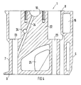
- the almost diagonally running deck together with the collecting duct allows cross-flow cooling of each cylinder, which cools the cylinder head evenly and effectively, and a low-resistance outflow of the heated water through the collecting duct.
- the diagonal course of the deck keeps the amount of water in the area of the spark plug inclined to a wall delimiting the cylinder head low and leads the water transversely and quickly to the area of the outlet duct which is highly thermally stressed.
- the arrangement of the collecting channel in the oil-carrying area enables a straight, low-resistance design of this channel.
- the inlets arranged on the underside of the cylinder head for the cooling water flowing from the crankcase into the cylinder head are dimensioned such that the inlets assigned to the thermally loaded flange side supply approximately 2/3 of the total amount of water.
- the inner boundary wall of the collecting duct has a smooth surface and is connected to the deck, so that the entire oil-carrying area can be formed in one piece upwards when the cylinder head is cast.
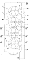
- a cylinder head 1 of a water-cooled internal combustion engine has for each cylinder 2 an inlet duct 4 serving for gas exchange in a combustion chamber 3 and an outlet duct 5, both of which open into a flange side 6 which laterally delimits the cylinder head 1.
- a delimiting wall 7 runs parallel to this flange side 6, and a cylinder head top 8 and a cylinder head bottom 9 of the cylinder head 1 run at right angles to this.
- the gas exchange is controlled by a camshaft, not shown, held in bearings 10, which acts on cup tappets, not shown, mounted in bores 11 on valves, also not shown, sliding in guides 12.
- Each combustion chamber 3 is assigned an ignition plug (not shown) which is inclined along an axis Z by means of an opening 13.
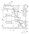
- the deck 15 separates a water-carrying area W facing the combustion chamber 3 from an oil-carrying area S which receives the valve control.
- the cylinder head underside 9 has inlets 17 and 18, which lead cooling water into the cylinder head 1 from a crankcase of the internal combustion engine, not shown.
- the entrances 17 and 18 are connected to cavities 19 and 20, the cavity 19 washing around the inlet and outlet channels 4 and 5 and opening into the collecting channel 16 at its geodetically highest point via a connection 21.
- the cavity 20 flows around the guide 12 and is connected to the cavity 19 adjacent to the deck 15.
- transverse walls 22 are arranged in the cylinder head 1 between adjacent cylinders 2 and have receptacles 23 for cylinder head screws, lubricating oil bores 24 and openings 25.
- cooling water flows through the entrances 17, 18 into the cavities 19, 20 and through the connection 21 into the collecting duct 16. With respect to each cylinder 2, cross-flow cooling is thus established, which ensures uniform and intensive cooling of the cylinders 2 Areas of the cylinder head 1 causes.
- the flow resistance within the collecting channel 16 is very low, since it is not deflected, for example, by laying it in the oil-carrying area S. experienced through gas exchange channels. This low resistance causes a rapid flow through the cavities 19, 20 and thus rapid heating of the water in the starting phase of the internal combustion engine and effective cooling in continuous operation.
- connection of an inner boundary wall 27 of the collecting duct 16 to the deck 15 and its smooth-surface design permit simple shaping of the oil-carrying area S when casting the cylinder head 1.
- the openings 25 simplify the core bearings during casting, since only a single overall core is thus required, otherwise cores separated from each other by the transverse walls 22 would have to be stored for each cylinder 2.
Landscapes
- Engineering & Computer Science (AREA)
- Chemical & Material Sciences (AREA)
- Combustion & Propulsion (AREA)
- Mechanical Engineering (AREA)
- General Engineering & Computer Science (AREA)
- Cylinder Crankcases Of Internal Combustion Engines (AREA)
Applications Claiming Priority (2)
| Application Number | Priority Date | Filing Date | Title |
|---|---|---|---|
| DE4036810 | 1990-11-19 | ||
| DE4036810A DE4036810C1 (cg-RX-API-DMAC7.html) | 1990-11-19 | 1990-11-19 |
Publications (2)
| Publication Number | Publication Date |
|---|---|
| EP0486771A1 EP0486771A1 (de) | 1992-05-27 |
| EP0486771B1 true EP0486771B1 (de) | 1993-09-29 |
Family
ID=6418534
Family Applications (1)
| Application Number | Title | Priority Date | Filing Date |
|---|---|---|---|
| EP91114129A Expired - Lifetime EP0486771B1 (de) | 1990-11-19 | 1991-08-23 | Zylinderkopf für eine wassergekühlte Brennkraftmaschine |
Country Status (3)
| Country | Link |
|---|---|
| EP (1) | EP0486771B1 (cg-RX-API-DMAC7.html) |
| DE (2) | DE4036810C1 (cg-RX-API-DMAC7.html) |
| RU (1) | RU1838648C (cg-RX-API-DMAC7.html) |
Families Citing this family (6)
| Publication number | Priority date | Publication date | Assignee | Title |
|---|---|---|---|---|
| EP0744542B1 (de) | 1995-05-22 | 1999-08-11 | Dr.Ing.h.c. F. Porsche Aktiengesellschaft | Zylinderkopf für eine wassergekühlte, mehrzylindrige Brennkraftmaschine |
| EP1538327B1 (de) * | 2003-12-04 | 2010-06-16 | Ford Global Technologies, LLC, A subsidary of Ford Motor Company | Zylinderkopf mit einem Kühlmittelmantel, der einen Kühlmantelkern und eine Entlüftungsleiste umfasst |
| DE102007027719B4 (de) * | 2007-06-15 | 2015-05-13 | Audi Ag | Brennkraftmaschine mit einem Heizungskreislauf und einem Kühlkreislauf |
| AT506468B1 (de) | 2009-03-24 | 2010-12-15 | Avl List Gmbh | Zylinderkopf einer brennkraftmaschine |
| DE102013113609B4 (de) | 2013-12-06 | 2022-02-24 | Dr. Ing. H.C. F. Porsche Aktiengesellschaft | Kurbelgehäuse mit einer Kühlwasserverteilung für eine mehrzylindrige Brennkraftmaschine |
| JP6341100B2 (ja) * | 2015-01-15 | 2018-06-13 | トヨタ自動車株式会社 | シリンダヘッド |
Family Cites Families (5)
| Publication number | Priority date | Publication date | Assignee | Title |
|---|---|---|---|---|
| BE538641A (cg-RX-API-DMAC7.html) * | ||||
| US2094893A (en) * | 1933-09-02 | 1937-10-05 | Continental Motors Corp | Engine |
| GB1002846A (en) * | 1963-02-27 | 1965-09-02 | Vauxhall Motors Ltd | Internal combustion engine cylinder head |
| GB1031571A (en) * | 1964-01-14 | 1966-06-02 | Henry Weslake | Improvements in or relating to cylinder heads for internal combustion engines |
| DE3208341A1 (de) * | 1982-03-09 | 1983-09-15 | Klöckner-Humboldt-Deutz AG, 5000 Köln | Zylinderkopf fuer eine wassergekuehlte brennkraftmaschine |
-
1990
- 1990-11-19 DE DE4036810A patent/DE4036810C1/de not_active Expired - Lifetime
-
1991
- 1991-02-18 RU SU914894446A patent/RU1838648C/ru active
- 1991-08-23 DE DE91114129T patent/DE59100434D1/de not_active Expired - Fee Related
- 1991-08-23 EP EP91114129A patent/EP0486771B1/de not_active Expired - Lifetime
Also Published As
| Publication number | Publication date |
|---|---|
| EP0486771A1 (de) | 1992-05-27 |
| DE4036810C1 (cg-RX-API-DMAC7.html) | 1991-12-05 |
| DE59100434D1 (de) | 1993-11-04 |
| RU1838648C (ru) | 1993-08-30 |
Similar Documents
| Publication | Publication Date | Title |
|---|---|---|
| DE2417925C2 (de) | Flüssigkeitsgekühlte Mehrzylinder-Brennkraftmaschine | |
| DE10202661B4 (de) | Zylinderkopf für mehrere Zylinder | |
| EP0952325A2 (de) | Brennkraftmaschine | |
| EP1516113B1 (de) | Gekühlter zylinderkopf für eine kolbenbrennkraftmaschine | |
| DE2825870A1 (de) | Verbrennungsmotor | |
| DE2839199C2 (de) | Im Druckgießverfahren herstellbarer Zylinderkopf für wassergekühlte Brennkraftmaschinen | |
| DE4437714C2 (de) | Zylinderkopfabdeckung | |
| DE102018116973B4 (de) | Flüssigkeitsgekühltes Kurbelgehäuse für eine Brennkraftmaschine | |
| DE3544213C2 (cg-RX-API-DMAC7.html) | ||
| DE1476397A1 (de) | Wassergekuehlte Brennkraftmaschine | |
| AT402325B (de) | Zylinderkopf einer flüssigkeitsgekühlten brennkraftmaschine mit in reihe angeordneten zylindern | |
| DE4421057C1 (de) | Zylinderkopfanordnung einer Brennkraftmaschine | |
| EP0486771B1 (de) | Zylinderkopf für eine wassergekühlte Brennkraftmaschine | |
| DE2824132A1 (de) | Zylinderkopf fuer eine luftgekuehlte brennkraftmaschine | |
| DE3326317C2 (cg-RX-API-DMAC7.html) | ||
| DE102004019853B4 (de) | Zylinderkopfstruktur | |
| DE602004001614T2 (de) | Eine Mehrzylinderbrennkraftmaschine und Verfahren zur wahlweisen Herstellung der Mehrzylinderbrennkraftmaschinen | |
| DE19701543B4 (de) | Kühlanordnung in einem Motorblock | |
| DE102009008237B4 (de) | Brennkraftmaschine mit getrennten Kühlmittelräumen im Zylinderkopf | |
| DE69519326T2 (de) | Brennkraftmaschine | |
| DE3546436C2 (de) | Flüssigkeitsgekühlter Vierventil-Zylinderkopf für eine mehrzylindrige Brennkraftmaschine | |
| AT5939U1 (de) | Zylinderkopf | |
| DE60028267T2 (de) | Brennkraftmaschine und ihre Benutzung | |
| DE69105568T2 (de) | Kühlkreislauf eines Zylinderkopfes für eine Brennkraftmaschine. | |
| DE4322030A1 (de) | Brennkraftmaschine mit zwei Zylinderreihen |
Legal Events
| Date | Code | Title | Description |
|---|---|---|---|
| PUAI | Public reference made under article 153(3) epc to a published international application that has entered the european phase |
Free format text: ORIGINAL CODE: 0009012 |
|
| AK | Designated contracting states |
Kind code of ref document: A1 Designated state(s): DE FR GB IT SE |
|
| 17P | Request for examination filed |
Effective date: 19920923 |
|
| 17Q | First examination report despatched |
Effective date: 19930219 |
|
| ITF | It: translation for a ep patent filed | ||
| GRAA | (expected) grant |
Free format text: ORIGINAL CODE: 0009210 |
|
| AK | Designated contracting states |
Kind code of ref document: B1 Designated state(s): DE FR GB IT SE |
|
| REF | Corresponds to: |
Ref document number: 59100434 Country of ref document: DE Date of ref document: 19931104 |
|
| ET | Fr: translation filed | ||
| GBT | Gb: translation of ep patent filed (gb section 77(6)(a)/1977) |
Effective date: 19931101 |
|
| PLBE | No opposition filed within time limit |
Free format text: ORIGINAL CODE: 0009261 |
|
| STAA | Information on the status of an ep patent application or granted ep patent |
Free format text: STATUS: NO OPPOSITION FILED WITHIN TIME LIMIT |
|
| PGFP | Annual fee paid to national office [announced via postgrant information from national office to epo] |
Ref country code: SE Payment date: 19940809 Year of fee payment: 4 |
|
| 26N | No opposition filed | ||
| EAL | Se: european patent in force in sweden |
Ref document number: 91114129.9 |
|
| PG25 | Lapsed in a contracting state [announced via postgrant information from national office to epo] |
Ref country code: SE Effective date: 19950824 |
|
| EUG | Se: european patent has lapsed |
Ref document number: 91114129.9 |
|
| PGFP | Annual fee paid to national office [announced via postgrant information from national office to epo] |
Ref country code: DE Payment date: 19970812 Year of fee payment: 7 |
|
| PGFP | Annual fee paid to national office [announced via postgrant information from national office to epo] |
Ref country code: GB Payment date: 19970814 Year of fee payment: 7 |
|
| PGFP | Annual fee paid to national office [announced via postgrant information from national office to epo] |
Ref country code: FR Payment date: 19970829 Year of fee payment: 7 |
|
| PG25 | Lapsed in a contracting state [announced via postgrant information from national office to epo] |
Ref country code: GB Free format text: LAPSE BECAUSE OF NON-PAYMENT OF DUE FEES Effective date: 19980823 |
|
| GBPC | Gb: european patent ceased through non-payment of renewal fee |
Effective date: 19980823 |
|
| PG25 | Lapsed in a contracting state [announced via postgrant information from national office to epo] |
Ref country code: FR Free format text: LAPSE BECAUSE OF NON-PAYMENT OF DUE FEES Effective date: 19990430 |
|
| PG25 | Lapsed in a contracting state [announced via postgrant information from national office to epo] |
Ref country code: DE Free format text: LAPSE BECAUSE OF NON-PAYMENT OF DUE FEES Effective date: 19990601 |
|
| REG | Reference to a national code |
Ref country code: FR Ref legal event code: ST |
|
| PG25 | Lapsed in a contracting state [announced via postgrant information from national office to epo] |
Ref country code: IT Free format text: LAPSE BECAUSE OF NON-PAYMENT OF DUE FEES;WARNING: LAPSES OF ITALIAN PATENTS WITH EFFECTIVE DATE BEFORE 2007 MAY HAVE OCCURRED AT ANY TIME BEFORE 2007. THE CORRECT EFFECTIVE DATE MAY BE DIFFERENT FROM THE ONE RECORDED. Effective date: 20050823 |