EP0486641B1 - Isolierverkleidung - Google Patents
Isolierverkleidung Download PDFInfo
- Publication number
- EP0486641B1 EP0486641B1 EP91910554A EP91910554A EP0486641B1 EP 0486641 B1 EP0486641 B1 EP 0486641B1 EP 91910554 A EP91910554 A EP 91910554A EP 91910554 A EP91910554 A EP 91910554A EP 0486641 B1 EP0486641 B1 EP 0486641B1
- Authority
- EP
- European Patent Office
- Prior art keywords
- wall
- ceiling
- fastening
- module
- fiber mats
- Prior art date
- Legal status (The legal status is an assumption and is not a legal conclusion. Google has not performed a legal analysis and makes no representation as to the accuracy of the status listed.)
- Expired - Lifetime
Links
- 239000000835 fiber Substances 0.000 claims abstract description 18
- 239000000463 material Substances 0.000 claims description 2
- 238000005253 cladding Methods 0.000 description 5
- 230000037431 insertion Effects 0.000 description 1
- 238000003780 insertion Methods 0.000 description 1
- 238000009413 insulation Methods 0.000 description 1
- 238000004519 manufacturing process Methods 0.000 description 1
- 239000002184 metal Substances 0.000 description 1
Images
Classifications
-
- E—FIXED CONSTRUCTIONS
- E04—BUILDING
- E04F—FINISHING WORK ON BUILDINGS, e.g. STAIRS, FLOORS
- E04F13/00—Coverings or linings, e.g. for walls or ceilings
- E04F13/07—Coverings or linings, e.g. for walls or ceilings composed of covering or lining elements; Sub-structures therefor; Fastening means therefor
- E04F13/08—Coverings or linings, e.g. for walls or ceilings composed of covering or lining elements; Sub-structures therefor; Fastening means therefor composed of a plurality of similar covering or lining elements
- E04F13/0801—Separate fastening elements
- E04F13/0832—Separate fastening elements without load-supporting elongated furring elements between wall and covering elements
- E04F13/0833—Separate fastening elements without load-supporting elongated furring elements between wall and covering elements not adjustable
- E04F13/0835—Separate fastening elements without load-supporting elongated furring elements between wall and covering elements not adjustable the fastening elements extending into the back side of the covering elements
-
- F—MECHANICAL ENGINEERING; LIGHTING; HEATING; WEAPONS; BLASTING
- F27—FURNACES; KILNS; OVENS; RETORTS
- F27D—DETAILS OR ACCESSORIES OF FURNACES, KILNS, OVENS OR RETORTS, IN SO FAR AS THEY ARE OF KINDS OCCURRING IN MORE THAN ONE KIND OF FURNACE
- F27D1/00—Casings; Linings; Walls; Roofs
- F27D1/14—Supports for linings
- F27D1/144—Supports for ceramic fibre materials
Definitions
- the invention relates to an insulating cladding comprising a plurality of modules for walls, ceilings or the like, each module consisting of a plurality of fiber mats held together to form a cuboid body and with at least one crossbar extending parallel to the wall, ceiling or the like in the body which is encompassed by at least one fastening element which can be fastened to the wall, ceiling or the like, can be arranged on the wall, ceiling or the like.
- US Pat. No. 3,832,815 describes a module consisting of fiber mats and an insulating cladding made of such modules.
- the fiber mats joined together to form a module are arranged between angle strips which abut the outer edges of the outermost fiber mat.
- Cross bars extend through the fiber mats and aligned bores in the angle strips, on the ends of which protrude beyond the angle strips, securing elements for holding together of the module or the fiber mats are provided.
- holders are used which surround the cross bars and are guided through bores in the wall.
- hairpin-like elements are used to fasten the module to a wall, which elements are inserted between the parting lines of the fiber mats, placed around the crossbars and then clamped to corresponding devices on the wall.
- This type of attachment of the modules to the wall is tedious, since the hairpin-like elements not only have to be inserted into a joint between two fiber mats that correspond to the attachment device on the wall, but also have to be placed around the crossbars and clamped to the attachment device.
- the object of the invention is now to facilitate the assembly of sound and / or heat insulation cladding of walls, ceilings or the like. Made of fiber mats assembled into modules.
- the areas of the fasteners projecting into the body are designed as plates with a plurality of bores which are randomly arranged closely next to one another for receiving the cross bars.
- the assembly of the insulating panel with the fasteners according to the invention is very simple, after the arrangement of the fasteners on the wall, ceiling or the like. This can be facilitated by the fact that they are made of an L-shaped sheet-shaped material, the Legs extending parallel to an outer surface of the body are attached to corresponding devices of the wall, the body only has to be pressed against the legs of the fastening elements pointing away from the wall, extending parallel to the fiber mats and provided with the bores, in order to secure them in the body to be placed between the fiber mats. Then the cross bars from the side in the body, the z and before and during assembly in a conventional manner. B. is held together by tapes and cardboard, inserted and inserted through a hole in the fastener.
- the body 1 shown consists of a plurality of fiber mats 2 arranged next to one another, which are held together by cross bars 3 as a cuboid block.
- one leg 5 of L-shaped fastening elements 6, which can be produced by edges of sheet metal strips, is inserted into the mats 2 or joints 4.
- This leg 5 arranged between the fiber mats 2 has a multiplicity of bores 7.
- a cross bar 3 extends through one of these bores 7 and is inserted laterally into the body 1 and holds the body 1 on the fastening element 6.
- a tip 9 at the end of the crossbar 3 projecting into the body 1 not only facilitates its insertion into the body 1. This tip 9 is also a guide element when the crossbar 3 is pushed through a bore 7 in the leg 5.
- the other leg 8 of the fastening element 6 lies on the outside of the body 1 and has devices (not shown) with which the latter and thus the body 1 can be attached to a wall (not shown).
Landscapes
- Engineering & Computer Science (AREA)
- Architecture (AREA)
- Civil Engineering (AREA)
- Mechanical Engineering (AREA)
- General Engineering & Computer Science (AREA)
- Ceramic Engineering (AREA)
- Chemical & Material Sciences (AREA)
- Structural Engineering (AREA)
- Building Environments (AREA)
- Continuous Casting (AREA)
- Finishing Walls (AREA)
- Input Circuits Of Receivers And Coupling Of Receivers And Audio Equipment (AREA)
- Materials For Medical Uses (AREA)
- Yarns And Mechanical Finishing Of Yarns Or Ropes (AREA)
Description
- Die Erfindung betrifft eine Isolierverkleidung aus einer Vielzahl von Modulen für Wände, Decken od. dgl., wobei jedes Modul aus einer Vielzahl von zu einem quaderförmigen Körper zusammengehaltener Fasermatten besteht und mit mindestens einem sich parallel zur Wand, Decke oder dgl. im Körper erstreckenden Querstab, der von mindestens einem an der Wand, Decke oder dgl. befestigbaren Befestigungselement umgriffen wird, an der Wand, Decke oder dgl. anordenbar ist.
- In der US-A 3 832 815 ist ein aus Fasermatten bestehendes Modul sowie eine Isolierverkleidung aus derartigen Modulen beschrieben. Die zu einem Modul zusammengefügten Fasermatten sind zwischen Winkelleisten angeordnet, die an den Außenkanten der jeweils äußersten Fasermatte anliegen. Durch die Fasermatten und fluchtende Bohrungen in den Winkelleisten erstrecken sich Querstäbe, auf deren über die Winkelleisten vorstehende Enden Sicherungselemente zum Zusammenhalten des Modules bzw. der Fasermatten vorgesehen sind. Zum Befestigen eines derartigen Modules an der zu isolierenden Wand dienen Halter, die die Querstäbe umgreifen und durch Bohrungen in der Wand geführt sind. Diese Art dar Herstellung und Befestigung der Module an der Wand ist aufwendig, indem nicht nur die Fasermatten mit den Winkelleisten zu vereinigen sind, sondern auch die Module nach dem Verbinden der Querstäbe mit den Haltern zur Anlage an die Wand gebracht werden müssen.
- Bei einer anderen aus der DE-PS 2 231 658 bekannten Isolierverkleidung dienen zur Befestigung des Modules an einer Wand haarnadelartige Elemente, die zwischen die Trennfugen der Fasermatten eingeführt, um die Querstäbe gelegt und anschließend an entsprechende Einrichtungen an der Wand verklemmt werden. Diese Art der Befestigung der Module an der Wand ist mühsam, da die haarhaarnadelartigen Elemente nicht nur in eine Trennfuge zwischen zwei Fasermatten, die mit der Befestigungseinrichtung an der Wand korrespondiert eingeführt, sondern auch noch um die Querstäbe gelegt sowie an der Befestigungseinrichtung verklemmt werden müssen.
- Aufgabe der Erfindung ist es nun, die Montage von Schall- und/oder Wärmeschutzverkleidungen von Wänden, Decken oder dgl. aus zu Modulen zusammengefügten Fasermatten zu erleichtern.
- Diese Aufgabe wird erfindungsgemäß dadurch gelöst, daß die in den Körper ragenden Bereiche der Befestigungselemente als Platten mit einer Vielzahl von wahllos dicht nebeneinander angeordneten Bohrungen zur Aufnahme der Querstäbe ausgebildet sind.
- Die Montage der Isolierverkleidung mit den Befestigungselementen nach der Erfindung ist denkbar einfach, Nach der Anordnung der Befestigungselemente an der Wand, Decke oder dgl., was dadurch erleichtert werden kann, daß diese aus zu einem L-Profil geformten tafelförmigen Material gefertigt sind, deren sich parallel zu einer Außenfläche des Körpers erstreckende Schenkel an entsprechenden Einrichtungen der Wand angebracht werden, muß der Körper nur gegen die von der Wand wegweisenden, sich parallel zu den Fasermatten erstreckenden sowie mit den Bohrungen versehenen Schenkel der Befestigungselemente gepreßt werden, um diese im Körper zwischen den Fasermatten anzuordnen. Danach werden die Querstäbe von der Seite her in den Körper, der vor und während der Montage in an sich bekannter Weise z. B. durch Bänder und Kartonagen zusammengepreßt gehalten wird, eingeführt und durch eine Bohrung im Befestigungselement gesteckt. Dies ist nicht nur wegen der Vielzahl der siebartig am Befestigungselement vorgesehenen Bohrungen, sondern bei einer bevorzugten Ausbildung der Erfindung auch durch das mit einer Spitze versehene in den Körper einzuführende Ende der Querstäbe problemlos möglich. Nachdem eine Wand mit derartigen Körpern oder Modulen vollständig bestückt ist, werden die Elemente, die die Körper zusammengepreßt gehalten haben, gelöst, worauf die vorgespannten Körper auffedern und die durch die Montage bedingten Spalten zwischen einzelnen Körpern geschlossen werden.
- Ein Ausführungsbeispiel der Erfindung wird noch an Hand der Zeichnungen beschrieben. Es stellen dar:
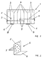
- Fig. 1
- eine schematische Ansicht des Modules oder Körpers einer Isolierverkleidung einer Wand,
- Fig. 2
- eine schematisch perspektivische Ansicht eines Befestigungselementes für den Körper nach Fig. 1.
- Der dargestellte Körper 1 besteht aus einer Vielzahl nebeneinander angeordneter Fasermatten 2, die von Querstäben 3 als quaderförmiger Block zusammengehalten werden. Parallel zu den Fugen 4 der einzelnen Fasermatten 2 ist in die Matten 2 oder Fugen 4 der eine Schenkel 5 von L-förmigen Befestigungselementen 6, die durch Kanten von Blechstreifen gefertigt werden können, eingefügt. Dieser zwischen den Fasermatten 2 angeordnete Schenkel 5 weist eine Vielzahl von Bohrungen 7 auf. Durch eine dieser Bohrungen 7 erstreckt sich ein Querstab 3, der seitlich in den Körper 1 eingeführt wird und den Körper 1 am Befestigungselement 6 festhält. Eine Spitze 9 am in den Körper 1 ragenden Ende des Querstabes 3 erleichtert nicht nur dessen Einschieben in den Körper 1. Diese Spitze 9 ist auch ein Führungselement beim Durchstecken des Querstabes 3 durch eine Bohrung 7 im Schenkel 5.
- Der andere Schenkel 8 des Befestigungselementes 6 liegt außen am Körper 1 an und weist nicht gezeigte Einrichtungen auf, mit denen dieser und damit der Körper 1 an einer Wand (nicht dargestellt) angebracht werden kann.
Claims (3)
- Isolierverkleidung aus einer Vielzahl von Modulen für Wände, Decken od. dgl., wobei jedes Modul aus einer Vielzahl von zu einem quaderförmigen Körper (1) zusammengehaltener Fasermatten (2) besteht und mit mindestens einem sich parallel zur Wand, Decke od. dgl. im Körper (1) erstreckenden Querstab (3), der von mindestens einem an der Wand, Decke od. dgl. befestigbaren Befestigungselement (6) umgriffen wird, an der Wand, Decke od. dgl. anordenbar ist, dadurch gekennzeichnet, daß die in den Körper (1) ragenden Bereiche (5) der Befestigungselemente (6) als Platten mit einer Vielzahl von wahllos dicht nebeneinander angeordneten Bohrungen (7) zur Aufnahme der Querstäbe (3) ausgebildet sind.
- Isolierverkleidung nach Anspruch 1, dadurch gekennzeichnet, daß die Befestigungselemente (5) aus zu einem L-Profil geformten tafelförmigen Material gefertigt sind, wobei der sich parallel zur Außenfläche des Körpers (1) erstreckende Schenkel (8) des L-Profiles Einrichtungen zur Befestigung des Körpers (1) an der Wand aufweist.
- Isolierverkleidung nach Anspruch 1 oder 2, dadurch gekennzeichnet, daß das in den Körper (1) eingeführte Ende des Querstabes (3) mit einer Spitze (9) versehen ist.
Applications Claiming Priority (3)
| Application Number | Priority Date | Filing Date | Title |
|---|---|---|---|
| DE9006687U DE9006687U1 (de) | 1990-06-13 | 1990-06-13 | Modul aus Fasermatten |
| DE9006687U | 1990-06-13 | ||
| PCT/EP1991/001076 WO1991019869A1 (de) | 1990-06-13 | 1991-06-08 | Modul aus fasermatten |
Publications (2)
| Publication Number | Publication Date |
|---|---|
| EP0486641A1 EP0486641A1 (de) | 1992-05-27 |
| EP0486641B1 true EP0486641B1 (de) | 1995-03-08 |
Family
ID=6854658
Family Applications (1)
| Application Number | Title | Priority Date | Filing Date |
|---|---|---|---|
| EP91910554A Expired - Lifetime EP0486641B1 (de) | 1990-06-13 | 1991-06-08 | Isolierverkleidung |
Country Status (8)
| Country | Link |
|---|---|
| EP (1) | EP0486641B1 (de) |
| JP (1) | JP2983632B2 (de) |
| AT (1) | ATE119611T1 (de) |
| BR (1) | BR9105787A (de) |
| CA (1) | CA2064079A1 (de) |
| DE (2) | DE9006687U1 (de) |
| ES (1) | ES2071316T3 (de) |
| WO (1) | WO1991019869A1 (de) |
Families Citing this family (1)
| Publication number | Priority date | Publication date | Assignee | Title |
|---|---|---|---|---|
| EP1399572A4 (de) | 2001-06-05 | 2005-02-09 | Karen K Oishi | Genexpression und produktion von tgf-b-proteinen einschliesslich der bioaktiven müllerschen inhibierenden substanz aus pflanzen |
Family Cites Families (4)
| Publication number | Priority date | Publication date | Assignee | Title |
|---|---|---|---|---|
| US3832815A (en) * | 1973-01-29 | 1974-09-03 | Flinn & Dreffein Eng Co | Modular insulation of fibrous material |
| US4605583A (en) * | 1984-07-30 | 1986-08-12 | Industrial Insulations, Inc. | Heat insulating module for a high temperature chamber |
| DE3523169C1 (de) * | 1985-06-28 | 1986-09-25 | Didier-Werke Ag, 6200 Wiesbaden | Faserfaltblock |
| FR2613400A1 (fr) * | 1987-04-06 | 1988-10-07 | Elf Isolation | Patte de fixation pour la pose mecanique de panneaux rigides sur une ossature, methode de pose desdits panneaux sur l'ossature en faisant appel a des pattes de fixation de ce type et structures ainsi realisees |
-
1990
- 1990-06-13 DE DE9006687U patent/DE9006687U1/de not_active Expired - Lifetime
-
1991
- 1991-06-08 JP JP3510065A patent/JP2983632B2/ja not_active Expired - Fee Related
- 1991-06-08 BR BR919105787A patent/BR9105787A/pt not_active IP Right Cessation
- 1991-06-08 WO PCT/EP1991/001076 patent/WO1991019869A1/de not_active Ceased
- 1991-06-08 EP EP91910554A patent/EP0486641B1/de not_active Expired - Lifetime
- 1991-06-08 ES ES91910554T patent/ES2071316T3/es not_active Expired - Lifetime
- 1991-06-08 CA CA002064079A patent/CA2064079A1/en not_active Abandoned
- 1991-06-08 DE DE59104873T patent/DE59104873D1/de not_active Expired - Lifetime
- 1991-06-08 AT AT91910554T patent/ATE119611T1/de not_active IP Right Cessation
Also Published As
| Publication number | Publication date |
|---|---|
| WO1991019869A1 (de) | 1991-12-26 |
| ATE119611T1 (de) | 1995-03-15 |
| CA2064079A1 (en) | 1991-12-14 |
| JP2983632B2 (ja) | 1999-11-29 |
| DE59104873D1 (de) | 1995-04-13 |
| DE9006687U1 (de) | 1990-10-11 |
| JPH05501898A (ja) | 1993-04-08 |
| BR9105787A (pt) | 1992-08-04 |
| EP0486641A1 (de) | 1992-05-27 |
| ES2071316T3 (es) | 1995-06-16 |
Similar Documents
| Publication | Publication Date | Title |
|---|---|---|
| DE4026502C1 (en) | Pocket spring core - has parallel chains of pocketed springs with insert slits extending over half chain height | |
| DE60109873T2 (de) | Klettverschluss mit magnetisch anziehbaren Elementen | |
| DE2306969B2 (de) | Klemmvorrichtung zur befestigung langgestreckter koerper | |
| DE1565994A1 (de) | Verfahren und Vorrichtung zum Zusammenbau elektronischer Geraete | |
| DE3240642C2 (de) | ||
| DE7826230U1 (de) | Führungs- und Markierungsstück für elektrische Kabel | |
| EP0486641B1 (de) | Isolierverkleidung | |
| DE4032563C2 (de) | ||
| CH667982A5 (de) | Halter. | |
| DE3913366C2 (de) | ||
| AT352973B (de) | Anordnung zum befestigen von wand- oder deckenverkleidungen | |
| DE3411619A1 (de) | Befestigungseinheit zum befestigen von platten und mittels der befestigungseinheiten zusammengebautes gestell | |
| DE2712702C2 (de) | Vorrichtung zur Festlegung von Einbauplatten in Berieselungseinbauten von Wärmetauschern | |
| DE69706662T2 (de) | Verfahren zur herstellung eines vorgespannten plattenförmigen bauteil | |
| DE3785971T2 (de) | Mauerverbinder. | |
| DE1760491C3 (de) | Verschlußglied für einen Reißverschluß mit Einzelverschlußgliedern | |
| DE2425633C3 (de) | Unterdecke für Demonstrationsräume | |
| DE2106218C3 (de) | Bewehrungselement für Beton o.dgl | |
| DE7119603U (de) | Abstandshalter aus kunststoff zur distanzierung von platten bei kuehltuermen | |
| DE2854681B2 (de) | Kontaktanordnung für Bandkabel | |
| DE7810381U1 (de) | Vorrichtung zum Befestigen eines Rohres auf einer Unterlage aus einer feinporigen Stoffschicht | |
| DE2751744A1 (de) | Vorrichtung zur halterung eines rohrbuendels | |
| DE29512920U1 (de) | Verbindungselement zum schraubenlosen Zusammenfügen von profilierten und gelochten Baugruppenträgern für Elektroinstallationsverteiler | |
| CH400510A (de) | Zugglied zur Verwendung in vorgespanntem Beton | |
| DE2453821C3 (de) | Steckschalttafel zum lötfreien Aufbau von elektronischen Versuchsschaltungen |
Legal Events
| Date | Code | Title | Description |
|---|---|---|---|
| PUAI | Public reference made under article 153(3) epc to a published international application that has entered the european phase |
Free format text: ORIGINAL CODE: 0009012 |
|
| 17P | Request for examination filed |
Effective date: 19920228 |
|
| AK | Designated contracting states |
Kind code of ref document: A1 Designated state(s): AT BE CH DE DK ES FR GB GR IT LI LU NL SE |
|
| 17Q | First examination report despatched |
Effective date: 19930511 |
|
| RAP1 | Party data changed (applicant data changed or rights of an application transferred) |
Owner name: GOSSLER FEUERFEST- UND ISOLIERTECHNIK GMBH |
|
| GRAA | (expected) grant |
Free format text: ORIGINAL CODE: 0009210 |
|
| AK | Designated contracting states |
Kind code of ref document: B1 Designated state(s): AT BE CH DE DK ES FR GB GR IT LI LU NL SE |
|
| PG25 | Lapsed in a contracting state [announced via postgrant information from national office to epo] |
Ref country code: DK Effective date: 19950308 Ref country code: GR Free format text: LAPSE BECAUSE OF FAILURE TO SUBMIT A TRANSLATION OF THE DESCRIPTION OR TO PAY THE FEE WITHIN THE PRESCRIBED TIME-LIMIT Effective date: 19950308 |
|
| REF | Corresponds to: |
Ref document number: 119611 Country of ref document: AT Date of ref document: 19950315 Kind code of ref document: T |
|
| REF | Corresponds to: |
Ref document number: 59104873 Country of ref document: DE Date of ref document: 19950413 |
|
| ITF | It: translation for a ep patent filed | ||
| GBT | Gb: translation of ep patent filed (gb section 77(6)(a)/1977) |
Effective date: 19950504 |
|
| PG25 | Lapsed in a contracting state [announced via postgrant information from national office to epo] |
Ref country code: SE Effective date: 19950608 |
|
| REG | Reference to a national code |
Ref country code: ES Ref legal event code: FG2A Ref document number: 2071316 Country of ref document: ES Kind code of ref document: T3 |
|
| ET | Fr: translation filed | ||
| PG25 | Lapsed in a contracting state [announced via postgrant information from national office to epo] |
Ref country code: LU Free format text: LAPSE BECAUSE OF NON-PAYMENT OF DUE FEES Effective date: 19950630 |
|
| PLBE | No opposition filed within time limit |
Free format text: ORIGINAL CODE: 0009261 |
|
| STAA | Information on the status of an ep patent application or granted ep patent |
Free format text: STATUS: NO OPPOSITION FILED WITHIN TIME LIMIT |
|
| 26N | No opposition filed | ||
| REG | Reference to a national code |
Ref country code: GB Ref legal event code: IF02 |
|
| PGFP | Annual fee paid to national office [announced via postgrant information from national office to epo] |
Ref country code: AT Payment date: 20030402 Year of fee payment: 13 |
|
| PGFP | Annual fee paid to national office [announced via postgrant information from national office to epo] |
Ref country code: GB Payment date: 20030416 Year of fee payment: 13 |
|
| PGFP | Annual fee paid to national office [announced via postgrant information from national office to epo] |
Ref country code: BE Payment date: 20030520 Year of fee payment: 13 |
|
| PGFP | Annual fee paid to national office [announced via postgrant information from national office to epo] |
Ref country code: FR Payment date: 20030613 Year of fee payment: 13 |
|
| PGFP | Annual fee paid to national office [announced via postgrant information from national office to epo] |
Ref country code: NL Payment date: 20030630 Year of fee payment: 13 |
|
| PGFP | Annual fee paid to national office [announced via postgrant information from national office to epo] |
Ref country code: CH Payment date: 20030909 Year of fee payment: 13 |
|
| PG25 | Lapsed in a contracting state [announced via postgrant information from national office to epo] |
Ref country code: GB Free format text: LAPSE BECAUSE OF NON-PAYMENT OF DUE FEES Effective date: 20040608 Ref country code: AT Free format text: LAPSE BECAUSE OF NON-PAYMENT OF DUE FEES Effective date: 20040608 |
|
| PGFP | Annual fee paid to national office [announced via postgrant information from national office to epo] |
Ref country code: ES Payment date: 20040625 Year of fee payment: 14 |
|
| PG25 | Lapsed in a contracting state [announced via postgrant information from national office to epo] |
Ref country code: CH Free format text: LAPSE BECAUSE OF NON-PAYMENT OF DUE FEES Effective date: 20040630 Ref country code: LI Free format text: LAPSE BECAUSE OF NON-PAYMENT OF DUE FEES Effective date: 20040630 Ref country code: BE Free format text: LAPSE BECAUSE OF NON-PAYMENT OF DUE FEES Effective date: 20040630 |
|
| BERE | Be: lapsed |
Owner name: *GOSSLER FEUERFEST- UND ISOLIERTECHNIK G.M.B.H. Effective date: 20040630 |
|
| PG25 | Lapsed in a contracting state [announced via postgrant information from national office to epo] |
Ref country code: NL Free format text: LAPSE BECAUSE OF NON-PAYMENT OF DUE FEES Effective date: 20050101 |
|
| GBPC | Gb: european patent ceased through non-payment of renewal fee |
Effective date: 20040608 |
|
| REG | Reference to a national code |
Ref country code: CH Ref legal event code: PL |
|
| PG25 | Lapsed in a contracting state [announced via postgrant information from national office to epo] |
Ref country code: FR Free format text: LAPSE BECAUSE OF NON-PAYMENT OF DUE FEES Effective date: 20050228 |
|
| NLV4 | Nl: lapsed or anulled due to non-payment of the annual fee |
Effective date: 20050101 |
|
| REG | Reference to a national code |
Ref country code: FR Ref legal event code: ST |
|
| PG25 | Lapsed in a contracting state [announced via postgrant information from national office to epo] |
Ref country code: IT Free format text: LAPSE BECAUSE OF NON-PAYMENT OF DUE FEES Effective date: 20050608 |
|
| PG25 | Lapsed in a contracting state [announced via postgrant information from national office to epo] |
Ref country code: ES Free format text: LAPSE BECAUSE OF NON-PAYMENT OF DUE FEES Effective date: 20050609 |
|
| REG | Reference to a national code |
Ref country code: ES Ref legal event code: FD2A Effective date: 20050609 |
|
| PGFP | Annual fee paid to national office [announced via postgrant information from national office to epo] |
Ref country code: DE Payment date: 20100730 Year of fee payment: 20 |
|
| REG | Reference to a national code |
Ref country code: DE Ref legal event code: R071 Ref document number: 59104873 Country of ref document: DE |
|
| REG | Reference to a national code |
Ref country code: DE Ref legal event code: R071 Ref document number: 59104873 Country of ref document: DE |
|
| PG25 | Lapsed in a contracting state [announced via postgrant information from national office to epo] |
Ref country code: DE Free format text: LAPSE BECAUSE OF EXPIRATION OF PROTECTION Effective date: 20110609 |