EP0486300B1 - Verarbeitungssystem für Videosignale - Google Patents
Verarbeitungssystem für Videosignale Download PDFInfo
- Publication number
- EP0486300B1 EP0486300B1 EP91310514A EP91310514A EP0486300B1 EP 0486300 B1 EP0486300 B1 EP 0486300B1 EP 91310514 A EP91310514 A EP 91310514A EP 91310514 A EP91310514 A EP 91310514A EP 0486300 B1 EP0486300 B1 EP 0486300B1
- Authority
- EP
- European Patent Office
- Prior art keywords
- signal
- signals
- vertical
- chrominance
- deemphasis
- Prior art date
- Legal status (The legal status is an assumption and is not a legal conclusion. Google has not performed a legal analysis and makes no representation as to the accuracy of the status listed.)
- Expired - Lifetime
Links
Images


Classifications
-
- H—ELECTRICITY
- H04—ELECTRIC COMMUNICATION TECHNIQUE
- H04N—PICTORIAL COMMUNICATION, e.g. TELEVISION
- H04N9/00—Details of colour television systems
- H04N9/79—Processing of colour television signals in connection with recording
- H04N9/80—Transformation of the television signal for recording, e.g. modulation, frequency changing; Inverse transformation for playback
- H04N9/81—Transformation of the television signal for recording, e.g. modulation, frequency changing; Inverse transformation for playback the individual colour picture signal components being recorded sequentially only
-
- H—ELECTRICITY
- H04—ELECTRIC COMMUNICATION TECHNIQUE
- H04N—PICTORIAL COMMUNICATION, e.g. TELEVISION
- H04N5/00—Details of television systems
- H04N5/76—Television signal recording
-
- H—ELECTRICITY
- H04—ELECTRIC COMMUNICATION TECHNIQUE
- H04N—PICTORIAL COMMUNICATION, e.g. TELEVISION
- H04N5/00—Details of television systems
- H04N5/76—Television signal recording
- H04N5/78—Television signal recording using magnetic recording
- H04N5/782—Television signal recording using magnetic recording on tape
- H04N5/7824—Television signal recording using magnetic recording on tape with rotating magnetic heads
- H04N5/7826—Television signal recording using magnetic recording on tape with rotating magnetic heads involving helical scanning of the magnetic tape
- H04N5/78263—Television signal recording using magnetic recording on tape with rotating magnetic heads involving helical scanning of the magnetic tape for recording on tracks inclined relative to the direction of movement of the tape
- H04N5/78266—Television signal recording using magnetic recording on tape with rotating magnetic heads involving helical scanning of the magnetic tape for recording on tracks inclined relative to the direction of movement of the tape using more than one track for the recording of one television field or frame, i.e. segmented recording
-
- H—ELECTRICITY
- H04—ELECTRIC COMMUNICATION TECHNIQUE
- H04N—PICTORIAL COMMUNICATION, e.g. TELEVISION
- H04N5/00—Details of television systems
- H04N5/76—Television signal recording
- H04N5/91—Television signal processing therefor
- H04N5/92—Transformation of the television signal for recording, e.g. modulation, frequency changing; Inverse transformation for playback
- H04N5/928—Transformation of the television signal for recording, e.g. modulation, frequency changing; Inverse transformation for playback the sound signal being pulse code modulated and recorded in time division multiplex with the modulated video signal
-
- H—ELECTRICITY
- H04—ELECTRIC COMMUNICATION TECHNIQUE
- H04N—PICTORIAL COMMUNICATION, e.g. TELEVISION
- H04N9/00—Details of colour television systems
- H04N9/79—Processing of colour television signals in connection with recording
- H04N9/793—Processing of colour television signals in connection with recording for controlling the level of the chrominance signal, e.g. by means of automatic chroma control circuits
- H04N9/7933—Processing of colour television signals in connection with recording for controlling the level of the chrominance signal, e.g. by means of automatic chroma control circuits the level control being frequency-dependent
- H04N9/7936—Processing of colour television signals in connection with recording for controlling the level of the chrominance signal, e.g. by means of automatic chroma control circuits the level control being frequency-dependent by using a preemphasis network at the recording side and a deemphasis network at the reproducing side
-
- H—ELECTRICITY
- H04—ELECTRIC COMMUNICATION TECHNIQUE
- H04N—PICTORIAL COMMUNICATION, e.g. TELEVISION
- H04N9/00—Details of colour television systems
- H04N9/79—Processing of colour television signals in connection with recording
- H04N9/797—Processing of colour television signals in connection with recording for recording the signal in a plurality of channels, the bandwidth of each channel being less than the bandwidth of the signal
- H04N9/7973—Processing of colour television signals in connection with recording for recording the signal in a plurality of channels, the bandwidth of each channel being less than the bandwidth of the signal by dividing the luminance or colour component signal samples or frequency bands among a plurality of recording channels
Definitions
- the luminance signal Y and the chrominance signals P R , P B which are sampled as 1320 and 330 samples over one horizontal scanning line, are stored in the TDM encoder 4.
- the stored signals are combined with each other, and the combined signals are supplied to digital-to-analog (D/A) converters 5A, 5B ( Figure 1) which convert them into two-channel TDM signals as shown in Figures 2D, 2E.
- D/A digital-to-analog
- Stereophonic audio signals for example, in righthand and lefthand channels are applied through respective input terminals 10L, 10R to a digital audio signal processor 11 which generates two-channel digital audio signals.
- These digital audio signals are supplied to the adders 9A, 9B by which they are added to the TDM signals from the frequency modulators 8A, 8B using time-division multiplexing.
- the recording area for the digital audio signals also includes 2.7 horizontal periods reserved as a recording area for an index signal with a guard of 1.7 horizontal periods interposed between the recording area for the index signal and the recording area for the first and second audio signals.
- the index signal recording area is followed by a guard of 1.7 horizontal periods.
- the TDM decoder 21 decodes the supplied digital signals into the luminance signal Y and the chrominance signals P R , P B which are separate from each other, and interpolates the chrominance signals P R , P B .
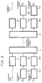
- Figure 5 of the accompanying drawings shows a circuit arrangement for effecting vertical nonlinear emphasis.
- the luminance signal Y is supplied through a vertical nonlinear emphasis circuit 31Y to the TDM encoder 4.
- the chrominance signals P R , P B are supplied to respective vertical nonlinear emphasis circuits 31R, 31B.
- the emphasized signals from the vertical nonlinear emphasis circuits 31R, 31B are then supplied to respective vertical low-pass filters 32R, 32B that remove aliasing distortions caused by the conversion into line sequential signals.
- the signals from the low-pass filters 32R, 32B are then supplied to the TDM encoder 4.
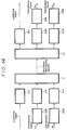
- the luminance signal Y decoded by the TDM decoder 21 is supplied to the output terminal through a vertical nonlinear deemphasis circuit 33Y.
- the chrominance signals P R , P B decoded by the TDM decoder 21 are supplied through respective vertical nonlinear deemphasis circuits 33R, 33B to interpolating filters 34R, 34B, respectively, which interpolate the supplied chrominance signals P R , P B in the vertical direction to compensate for the signal omission caused by the line sequential conversion.
- the signals which are omitted in alternate horizontal scanning periods by the line sequential conversion have two phases as shown in Figures 10B and 10C.
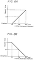
- the output signals had waveform distortions as indicated by solid lines a in Figures 11A and 11B of the accompanying drawings.
- Input signals had waveforms as indicated by solid lines b, and output signals with no emphasis and deemphasis had waveforms as indicated by solid lines c.
- At least preferred embodiments of the invention provide a video signal processing apparatus of simple circuit arrangement which is capable of effecting vertical emphasis and deemphasis on chrominance signals with low distortion.
Claims (7)
- Videosignal-Verarbeitungsvorrichtung mit:einem Kodierer (4) zum Umwandeln eines Chrominanzsignales (PR, PB) in ein Zeilenfolgesignal und zum Multiplexen des Zeilenfolgesignales mit einem Luminanzsignal (Y) bei Zeitkompression gemäß einem Zeitmultiplexen, wodurch ein zeitgemultiplextes Signal (Fig. 3) erzeugt wird,einer Vertikal-Anhebungsschaltung (31R, 31B), die mit einem Eingangsanschluß des Kodierers (4) zum Bewirken einer vertikalen nichtlinearen Anhebung an dem Chrominanzsignal (PR, PB) verbunden ist, undeinem Vertikal-Tiefpaßfilter (32R, 32B) zum Entfernen von Verfremdungsstörungen aus dem Chrominanzsignal (PR, PB) in Folge der Umwandlung des Chrominanzsignales (PR, PR) in das Zeilenfolgesignal, wobei die vertikale nichtlineare Anhebung an dem Chrominanzsignal (PR, PB) bewirkt wird, nachdem das Chrominanzsignal (PR, PB) von dem Vertikal-Tiefpaßfilter (32R, 32B) verarbeitet worden ist.
- Vorrichtung gemäß Anspruch 1, mit:einem Dekodierer (21) zum Dekodieren des zeitgemultiplexten Signales (Fig. 3) in das Chrominanz(PR, PB)- und das Luminanz(Y)-Signal,einer Vertikal-Rückentzerrungsschaltung (33R, 33B) zum Bewirken einer vertikalen nichtlinearen Rückentzerrung an dem durch den Dekodierer (21) dekodierten Chrominanzsignal (PR, PB), undeinem Interpolationsfilter (34R, 34B) zum Interpolieren des durch den Dekodierer (21) dekodierten Chrominanzsignales (PR, PB), wobei die Vertikal-Nichtlinear-Entzerrungsschaltung (33R, 33B) mit einem Eingangsanschluß des Interpolationsfilters (34R, 34B) verbunden ist.
- Vorrichtung gemäß Anspruch 1, mit:einem Dekodierer (21) zum Dekodieren des zeitgemultiplexten Signales (Fig. 3) in das Chrominanz(PR, PB)- und das Luminanz(Y)-Signal,einer Vertikal-Rückentzerrungsschaltung (33R, 33B) zum Bewirken einer vertikalen nichtlinearen Rückentzerrung an dem durch den Dekodierer (21) dekodierten Chrominanzsignal (PR, PB), undeinem Interpolationsfilter (34R, 34B) zum Interpolieren des durch den Dekodierer (21) dekodierten Chrominanzsignales (PR, PB), wobei die Vertikal-Nichtlinear-Rückentzerrungsschaltung (33R, 33B) mit einem Eingangsanschluß des Interpolationsfilters (34R, 34B) verbunden ist.
- Vorrichtung gemäß einem der vorherigen Ansprüche 1, 2 und 3, mit einer Horizontal-Anhebungsschaltung (35R, 35B) zum Bewirken einer horizontalen Anhebung bei dem Chrominanzsignal (PR, PB), wobei die Horizontal-Anhebungsschaltung (35R, 35B) mit einem Eingangsanschluß der Vertikal-Anhebungsschaltung (31R, 31B) verbunden ist.
- Vorrichtung gemäß einem der Ansprüche 2 und 3, mit einer Horizontal-Rückentzerrungsschaltung (36R, 36B) zum Bewirken einer horizontalen Rückentzerrung an dem durch den Dekodierer (21) dekodierten Chrominanzsignal (PR, PB), wobei die Horizontal-Rückentzerrungsschaltung (36R, 36B) mit einem Ausgangsanschluß der Vertikal-Rückentzerrungsschaltung (33R, 33B) verbunden ist.
- Video-Bandaufzeichnungs-/-wiedergabevorrichtung, aufweisend eine Videosignal-Verarbeitungsvorrichtung gemäß einem der vorhergehenden Ansprüche.
- Video-Bandaufzeichnungs-/-wiedergabevorrichtung gemäß Anspruch 6, mit einer Einrichtung zum Verarbeiten von Signalen für hochaufgelöstes Fernsehen.
Applications Claiming Priority (2)
| Application Number | Priority Date | Filing Date | Title |
|---|---|---|---|
| JP2309078A JPH04180492A (ja) | 1990-11-15 | 1990-11-15 | 映像信号記録再生装置 |
| JP309078/90 | 1990-11-15 |
Publications (3)
| Publication Number | Publication Date |
|---|---|
| EP0486300A2 EP0486300A2 (de) | 1992-05-20 |
| EP0486300A3 EP0486300A3 (en) | 1993-03-17 |
| EP0486300B1 true EP0486300B1 (de) | 1996-07-03 |
Family
ID=17988621
Family Applications (1)
| Application Number | Title | Priority Date | Filing Date |
|---|---|---|---|
| EP91310514A Expired - Lifetime EP0486300B1 (de) | 1990-11-15 | 1991-11-14 | Verarbeitungssystem für Videosignale |
Country Status (5)
| Country | Link |
|---|---|
| US (1) | US5267022A (de) |
| EP (1) | EP0486300B1 (de) |
| JP (1) | JPH04180492A (de) |
| KR (1) | KR100254503B1 (de) |
| DE (1) | DE69120633T2 (de) |
Families Citing this family (4)
| Publication number | Priority date | Publication date | Assignee | Title |
|---|---|---|---|---|
| EP0604154B1 (de) * | 1992-12-24 | 2000-02-09 | Victor Company Of Japan, Ltd. | Verfahren zur Vorverzerrung und Nachverzerrung von Videosignalen |
| JPH0787405A (ja) * | 1993-09-14 | 1995-03-31 | Sony Corp | 撮像装置 |
| CN1327714C (zh) * | 2004-01-17 | 2007-07-18 | 深圳创维-Rgb电子有限公司 | 一种逐行/隔行视频信号共享的输入通道及其方法 |
| US7375573B2 (en) * | 2006-05-25 | 2008-05-20 | Micron Technology, Inc. | De-emphasis system and method for coupling digital signals through capacitively loaded lines |
Family Cites Families (10)
| Publication number | Priority date | Publication date | Assignee | Title |
|---|---|---|---|---|
| US4612585A (en) * | 1982-09-10 | 1986-09-16 | Hitachi, Ltd. | Chrominance signal recording and reproducing apparatus |
| JPS59144288A (ja) * | 1983-02-07 | 1984-08-18 | Victor Co Of Japan Ltd | 映像信号記録再生装置 |
| JPS6030296A (ja) * | 1983-07-29 | 1985-02-15 | Victor Co Of Japan Ltd | 映像信号記録装置及び映像信号記録再生装置 |
| JPS6030295A (ja) * | 1983-07-29 | 1985-02-15 | Victor Co Of Japan Ltd | 搬送色信号の記録再生装置 |
| JPS6030285A (ja) * | 1983-07-29 | 1985-02-15 | Victor Co Of Japan Ltd | 映像信号記録再生装置 |
| JPS6093682A (ja) * | 1983-10-25 | 1985-05-25 | Sony Corp | デイジタル非線形プリエンフアシス回路 |
| JPS63257395A (ja) * | 1987-04-14 | 1988-10-25 | Sony Corp | カラ−映像信号及び音声信号の記録装置 |
| US4908697A (en) * | 1987-07-24 | 1990-03-13 | North American Philips Corporation | Two-line mac high definition television system |
| US5126846A (en) * | 1988-08-08 | 1992-06-30 | Kabushiki Kaisha Toshiba | Non-linear amplifier and non-linear emphasis/deemphasis circuit using the same |
| JPH0310480A (ja) * | 1989-06-07 | 1991-01-18 | Toshiba Corp | テレビジョン信号伝送装置およびテレビジョン信号受信装置 |
-
1990
- 1990-11-15 JP JP2309078A patent/JPH04180492A/ja active Pending
-
1991
- 1991-11-08 US US07/789,753 patent/US5267022A/en not_active Expired - Fee Related
- 1991-11-12 KR KR1019910020010A patent/KR100254503B1/ko not_active IP Right Cessation
- 1991-11-14 DE DE69120633T patent/DE69120633T2/de not_active Expired - Fee Related
- 1991-11-14 EP EP91310514A patent/EP0486300B1/de not_active Expired - Lifetime
Also Published As
| Publication number | Publication date |
|---|---|
| KR920011252A (ko) | 1992-06-27 |
| KR100254503B1 (ko) | 2000-05-01 |
| EP0486300A3 (en) | 1993-03-17 |
| JPH04180492A (ja) | 1992-06-26 |
| DE69120633T2 (de) | 1996-11-28 |
| EP0486300A2 (de) | 1992-05-20 |
| DE69120633D1 (de) | 1996-08-08 |
| US5267022A (en) | 1993-11-30 |
Similar Documents
| Publication | Publication Date | Title |
|---|---|---|
| JPH05168041A (ja) | 映像信号記録装置 | |
| KR970002148B1 (ko) | 칼라 영상 신호 및 음성 신호의 기록장치 | |
| US4691245A (en) | Method and apparatus for combining two color video signals | |
| KR920003371B1 (ko) | 텔레비젼 신호의 기록재생장치 | |
| KR970002147B1 (ko) | 컬러 성분 신호 변환 장치 | |
| EP0486300B1 (de) | Verarbeitungssystem für Videosignale | |
| US4654697A (en) | Video signal apparatus for processing a time-division-multiplex video signal having a buffer segment | |
| JPS63217790A (ja) | ビデオ信号記録再生装置 | |
| JP3010742B2 (ja) | 回転ヘッド型磁気記録再生装置 | |
| US4472746A (en) | Chrominance channel bandwidth modification system | |
| JPH0720262B2 (ja) | 映像信号記録再生装置 | |
| JPS61181286A (ja) | 画像信号のデイジタル記録装置 | |
| JP2569735B2 (ja) | 標準方式変換方法 | |
| JP2527819B2 (ja) | 映像信号処理装置 | |
| JP3066214B2 (ja) | 磁気記録再生装置 | |
| JP3084863B2 (ja) | 映像信号再生装置 | |
| JP2959329B2 (ja) | 映像信号記録方法 | |
| JPH0516234B2 (de) | ||
| JPH0530355B2 (de) | ||
| JPH06153153A (ja) | 磁気記録再生装置 | |
| JPH04302294A (ja) | 映像信号記録再生装置 | |
| JPH10174054A (ja) | 回転ヘッド型磁気記録再生装置 | |
| JPH05918B2 (de) | ||
| JPH07264627A (ja) | 映像信号処理回路 | |
| JPH10154302A (ja) | 磁気記録方法 |
Legal Events
| Date | Code | Title | Description |
|---|---|---|---|
| PUAI | Public reference made under article 153(3) epc to a published international application that has entered the european phase |
Free format text: ORIGINAL CODE: 0009012 |
|
| AK | Designated contracting states |
Kind code of ref document: A2 Designated state(s): DE FR GB |
|
| PUAL | Search report despatched |
Free format text: ORIGINAL CODE: 0009013 |
|
| AK | Designated contracting states |
Kind code of ref document: A3 Designated state(s): DE FR GB |
|
| 17P | Request for examination filed |
Effective date: 19930826 |
|
| 17Q | First examination report despatched |
Effective date: 19950915 |
|
| GRAH | Despatch of communication of intention to grant a patent |
Free format text: ORIGINAL CODE: EPIDOS IGRA |
|
| GRAH | Despatch of communication of intention to grant a patent |
Free format text: ORIGINAL CODE: EPIDOS IGRA |
|
| GRAA | (expected) grant |
Free format text: ORIGINAL CODE: 0009210 |
|
| AK | Designated contracting states |
Kind code of ref document: B1 Designated state(s): DE FR GB |
|
| REF | Corresponds to: |
Ref document number: 69120633 Country of ref document: DE Date of ref document: 19960808 |
|
| ET | Fr: translation filed | ||
| PLBE | No opposition filed within time limit |
Free format text: ORIGINAL CODE: 0009261 |
|
| STAA | Information on the status of an ep patent application or granted ep patent |
Free format text: STATUS: NO OPPOSITION FILED WITHIN TIME LIMIT |
|
| 26N | No opposition filed | ||
| PGFP | Annual fee paid to national office [announced via postgrant information from national office to epo] |
Ref country code: FR Payment date: 20011113 Year of fee payment: 11 |
|
| PGFP | Annual fee paid to national office [announced via postgrant information from national office to epo] |
Ref country code: GB Payment date: 20011114 Year of fee payment: 11 |
|
| PGFP | Annual fee paid to national office [announced via postgrant information from national office to epo] |
Ref country code: DE Payment date: 20011126 Year of fee payment: 11 |
|
| REG | Reference to a national code |
Ref country code: GB Ref legal event code: IF02 |
|
| PG25 | Lapsed in a contracting state [announced via postgrant information from national office to epo] |
Ref country code: GB Free format text: LAPSE BECAUSE OF NON-PAYMENT OF DUE FEES Effective date: 20021114 |
|
| PG25 | Lapsed in a contracting state [announced via postgrant information from national office to epo] |
Ref country code: DE Free format text: LAPSE BECAUSE OF NON-PAYMENT OF DUE FEES Effective date: 20030603 |
|
| GBPC | Gb: european patent ceased through non-payment of renewal fee | ||
| PG25 | Lapsed in a contracting state [announced via postgrant information from national office to epo] |
Ref country code: FR Free format text: LAPSE BECAUSE OF NON-PAYMENT OF DUE FEES Effective date: 20030731 |
|
| REG | Reference to a national code |
Ref country code: FR Ref legal event code: ST |