EP0485811B1 - Leuchte - Google Patents
Leuchte Download PDFInfo
- Publication number
- EP0485811B1 EP0485811B1 EP91118584A EP91118584A EP0485811B1 EP 0485811 B1 EP0485811 B1 EP 0485811B1 EP 91118584 A EP91118584 A EP 91118584A EP 91118584 A EP91118584 A EP 91118584A EP 0485811 B1 EP0485811 B1 EP 0485811B1
- Authority
- EP
- European Patent Office
- Prior art keywords
- lamp housing
- housing
- outer housing
- lamp
- connecting link
- Prior art date
- Legal status (The legal status is an assumption and is not a legal conclusion. Google has not performed a legal analysis and makes no representation as to the accuracy of the status listed.)
- Expired - Lifetime
Links
- 238000010276 construction Methods 0.000 claims 1
- 229910052736 halogen Inorganic materials 0.000 description 2
- 150000002367 halogens Chemical class 0.000 description 2
- 230000005855 radiation Effects 0.000 description 2
- 230000003068 static effect Effects 0.000 description 2
- 230000005540 biological transmission Effects 0.000 description 1
- 230000006735 deficit Effects 0.000 description 1
- 238000009434 installation Methods 0.000 description 1
Images

Classifications
-
- F—MECHANICAL ENGINEERING; LIGHTING; HEATING; WEAPONS; BLASTING
- F21—LIGHTING
- F21V—FUNCTIONAL FEATURES OR DETAILS OF LIGHTING DEVICES OR SYSTEMS THEREOF; STRUCTURAL COMBINATIONS OF LIGHTING DEVICES WITH OTHER ARTICLES, NOT OTHERWISE PROVIDED FOR
- F21V21/00—Supporting, suspending, or attaching arrangements for lighting devices; Hand grips
- F21V21/02—Wall, ceiling, or floor bases; Fixing pendants or arms to the bases
- F21V21/04—Recessed bases
-
- F—MECHANICAL ENGINEERING; LIGHTING; HEATING; WEAPONS; BLASTING
- F21—LIGHTING
- F21S—NON-PORTABLE LIGHTING DEVICES; SYSTEMS THEREOF; VEHICLE LIGHTING DEVICES SPECIALLY ADAPTED FOR VEHICLE EXTERIORS
- F21S8/00—Lighting devices intended for fixed installation
- F21S8/02—Lighting devices intended for fixed installation of recess-mounted type, e.g. downlighters
- F21S8/026—Lighting devices intended for fixed installation of recess-mounted type, e.g. downlighters intended to be recessed in a ceiling or like overhead structure, e.g. suspended ceiling
-
- F—MECHANICAL ENGINEERING; LIGHTING; HEATING; WEAPONS; BLASTING
- F21—LIGHTING
- F21S—NON-PORTABLE LIGHTING DEVICES; SYSTEMS THEREOF; VEHICLE LIGHTING DEVICES SPECIALLY ADAPTED FOR VEHICLE EXTERIORS
- F21S8/00—Lighting devices intended for fixed installation
- F21S8/02—Lighting devices intended for fixed installation of recess-mounted type, e.g. downlighters
- F21S8/028—Lighting devices intended for fixed installation of recess-mounted type, e.g. downlighters being retractable, i.e. having two fixed positions, one recessed, e.g. in a wall, floor or ceiling, and one extended when in use
-
- F—MECHANICAL ENGINEERING; LIGHTING; HEATING; WEAPONS; BLASTING
- F21—LIGHTING
- F21V—FUNCTIONAL FEATURES OR DETAILS OF LIGHTING DEVICES OR SYSTEMS THEREOF; STRUCTURAL COMBINATIONS OF LIGHTING DEVICES WITH OTHER ARTICLES, NOT OTHERWISE PROVIDED FOR
- F21V17/00—Fastening of component parts of lighting devices, e.g. shades, globes, refractors, reflectors, filters, screens, grids or protective cages
- F21V17/02—Fastening of component parts of lighting devices, e.g. shades, globes, refractors, reflectors, filters, screens, grids or protective cages with provision for adjustment
-
- F—MECHANICAL ENGINEERING; LIGHTING; HEATING; WEAPONS; BLASTING
- F21—LIGHTING
- F21V—FUNCTIONAL FEATURES OR DETAILS OF LIGHTING DEVICES OR SYSTEMS THEREOF; STRUCTURAL COMBINATIONS OF LIGHTING DEVICES WITH OTHER ARTICLES, NOT OTHERWISE PROVIDED FOR
- F21V21/00—Supporting, suspending, or attaching arrangements for lighting devices; Hand grips
- F21V21/14—Adjustable mountings
- F21V21/30—Pivoted housings or frames
Definitions
- the invention relates to a recessed ceiling light fixture with a stationary outer housing, a pivotably arranged lamp housing and a lamp holder, the lamp housing carrying the lamp holder being connected to the outer housing by a link arrangement.
- the outer housing can be used in a recess in the ceiling.
- a recessed luminaire with the features described above is known from US-A-3 974 371.
- the lamp housing is axially adjustable within the outer housing by the handlebar arrangement. Furthermore, sideways compensating movements are possible when the lamp housing is pivoted. Swiveling movement as well as axial movement and sideways movement are not coupled with each other.
- the lamp housing can be pivoted in any position, regardless of whether the lamp housing is inserted into the outer housing or is pulled out of the outer housing as part of the adjustment facility. It takes considerable skill to pivot the lamp housing so that on the one hand it does not protrude unnecessarily far on the underside of the outer housing and on the other hand the radiation output of the pivoted lamp housing is exposed. The necessary corrective measures are made more difficult by the fact that the handlebar arrangement must take up the weight of the lamp housing and must be sufficiently stiff for this purpose.
- Recessed luminaires with a stationary outer housing and a pivotably arranged lamp housing are also known in practice, in which the lamp housing has bearing journals on its lower casing section, which are rotatably held at corresponding bearing points of the outer housing.
- Such an arrangement is also not free from disadvantages. If the pivot pins are arranged in a vertical plane of symmetry running through the central axis of the outer housing, a part of the lamp housing of the same size corresponding to the pivoted-out part of the lamp housing is pivoted into the outer housing during the pivoting movement. The result of this is that the outer housing intersects the light cone, the resulting impairment increasing with an increasing swivel angle. An improvement can be achieved by an asymmetrical arrangement of the trunnions outside the plane of symmetry. With increasing eccentric storage, however, the problem arises that the lamp housing can no longer be held in a rotationally fixed manner by static friction at the bearing points. Finally, it is disadvantageous that a considerable gap must be maintained between the outer housing and the lamp housing.
- From DE-A-2 455 935 and US-A-4 602 319 headlights for motor vehicles with a lamp housing which can be retracted into the vehicle body are known.
- the lamp housing is connected to a handlebar arrangement of parallel, equally long handlebars and can be moved vertically while maintaining a parallel orientation.
- the invention has for its object to provide a recessed ceiling light in which it is ensured without corrective measures to be carried out manually that the radiation output of the lamp housing is exposed in all pivot positions.
- the handlebar arrangement has at least one handlebar pair made of links and of different lengths, which have a small handlebar distance in the side projection to a lower jacket section of the lamp housing and a large handlebar distance to those facing away from the light exit are connected to the upper edge of the outer housing, the two links with the lamp housing forming a four-bar linkage with only one degree of freedom of movement, the kinematics of which are set up so that the pivoting movement of the lamp housing is positively superimposed on a sideways and downward movement of the lamp housing.
- - Side projection means the image plane orthogonal to the swivel axes of the handlebars.
- the quadrilateral joint is an inevitable crank gear with a degree of freedom of movement. It comprises four links which are connected by four articulation points to form a closed swivel chain, one of the links being stationary (DUBBEL, Volume I, 13th edition, pages 856 to 858 ).
- the lamp housing and the two links form a total of three movable transmission members.
- the outer housing is the fourth fixed gear link. All gear links are rotatable with each other connected to an inevitable crank gear, the kinematics of which is set up in such a way that the pivoting movement of the lamp housing is superimposed on a sideways and downward movement.
- the handlebar pair arranged in the manner described consists of a short and a long handlebar.
- the short handlebar controls the sideways and downward movement and the long handlebar the swivel movement.
- the pivoting movement results from a rotary movement around the pivot point defined by the short handlebar at the end. Low static friction on the joints is sufficient to hold the lamp housing in any desired swivel position.
- the handlebar arrangement consists of two handlebar pairs which form congruent quadrilaterals in the side projection and support the lamp housing on both sides of a plane of symmetry running through the central axis of the outer housing.
- a structurally preferred embodiment provides that the long handlebar is fork-shaped and covers and encloses the lamp housing at a distance.
- the invention teaches that the outer housing has a cylindrical fastening collar and has a mounting flange held rotatably thereon and that the link arrangement is connected to the mounting flange. This can be achieved in a particularly simple manner in that the fastening flange is held on an annular groove of the fastening collar. It is understood that in all embodiments the lamp housing is tapered towards the top. A particularly small gap distance between the outer housing and the lamp housing can be realized if the lamp housing is designed as a spherical cap, at least in its pivotable section. A preferred embodiment of the invention provides that the lamp housing has a spherical cap-shaped support body and a reflector inserted therein.
- the lamp holder for. B. for a low-voltage halogen lamp attached. It is also expedient to arrange a stop pin for the lamp housing on the outer housing, against which the lamp housing rests in the pivoted-in basic position.
- the advantages of the invention can be seen in the fact that the beam output is exposed even when the lamp housing is pivoted and the light cone is not cut by the outer housing.
- the lamp housing is held in any swivel position due to the handlebar arrangement.
- the kinematics can easily be set up so that the distance between the outer housing and the lamp housing is small, particularly in the lower mouth region.
- the recessed luminaire shown in the figures is intended for installation in ceiling or wall surfaces.
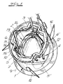
- the basic structure includes an outer housing 1, which can be fixedly inserted into a recess in the ceiling or wall surface, and a lamp housing 2 with a lamp holder 3.
- the lamp housing 2 is connected to the outer housing 1 by a handlebar arrangement 4 comprising at least two links 5, 6.
- the handlebars 5, 6 form with the lamp housing 2 an articulated quadrilateral, the kinematics of which is set up so that the pivoting movement of the lamp housing 2 is superimposed on a sideways and downward movement of the lamp housing 2.
- the pair of links forming a quadrilateral consists of a short link 5 and a long link 6.
- the two links 5, 6 are with a small in the side projection handlebar distance a to a lower jacket portion of the lamp housing 2 and with a large handlebar distance b to the upper edge of the External housing 1, which extends into the ceiling or wall recess connected.
- the short link 5 controls the sideways and downward movement of the lamp housing 2.
- the long link 6 controls the swiveling movement, namely by rotation about the pivot point 7 of the lamp housing 2 defined by the short link 5 7 with vertical and parallel to the central axis 8 of the outer housing 1 parallel alignment of the short handlebar 5 has taken its lower position shown in broken lines, the permissible pivoting angle of the lamp housing 2 has been reached.
- a swiveling movement beyond this angular position is possible, but this leads to the lamp housing being pivoted into the outer housing in some areas and the light cone being cut by the outer housing.
- the long handlebar 6 is fork-shaped and covers the lamp housing 2 at a distance.
- the handlebar arrangement 4 consists of two handlebar pairs 5, 6 and 5 ', 6', which form congruent quadrilaterals in the side projection and support the lamp housing 2 on both sides of a plane of symmetry 9 running through the central axis of the outer housing.
- the outer housing 1 has a cylindrical fastening collar 10 and a fastening flange 11 held thereon.
- the link arrangement 4 is connected to the fastening flange 11, which in turn is held on an annular groove 12 of the fastening collar 10.
- the lamp housing 2 has a spherical cap-shaped support body 13 with an inserted reflector 14 and a lamp holder 3 fastened on the outside, for example for a low-voltage halogen lamp.
- a stop pin 15 is arranged on the mounting flange 11 of the outer housing 1, on which the lamp housing 2 rests in the pivoted-in position.
- spreading spring elements 16 are arranged on the fastening collar 10, by means of which the fastening collar 10 can be locked in the associated recess in the ceiling or wall surface.
Landscapes
- Engineering & Computer Science (AREA)
- General Engineering & Computer Science (AREA)
- Non-Portable Lighting Devices Or Systems Thereof (AREA)
- Fastening Of Light Sources Or Lamp Holders (AREA)
Applications Claiming Priority (2)
| Application Number | Priority Date | Filing Date | Title |
|---|---|---|---|
| DE4036229A DE4036229A1 (de) | 1990-11-14 | 1990-11-14 | Leuchte |
| DE4036229 | 1990-11-14 |
Publications (3)
| Publication Number | Publication Date |
|---|---|
| EP0485811A2 EP0485811A2 (de) | 1992-05-20 |
| EP0485811A3 EP0485811A3 (de) | 1992-06-10 |
| EP0485811B1 true EP0485811B1 (de) | 1995-05-31 |
Family
ID=6418232
Family Applications (1)
| Application Number | Title | Priority Date | Filing Date |
|---|---|---|---|
| EP91118584A Expired - Lifetime EP0485811B1 (de) | 1990-11-14 | 1991-10-31 | Leuchte |
Country Status (3)
| Country | Link |
|---|---|
| US (1) | US5145249A (https=) |
| EP (1) | EP0485811B1 (https=) |
| DE (2) | DE4036229A1 (https=) |
Families Citing this family (26)
| Publication number | Priority date | Publication date | Assignee | Title |
|---|---|---|---|---|
| DE4114509C2 (de) * | 1991-05-03 | 1997-12-11 | Halloform Gmbh & Co Kg | Einbauleuchte mit Schwenkgehäuse |
| US5268824A (en) * | 1993-02-22 | 1993-12-07 | Accon, Inc. | Manually operated boat light |
| US5564815A (en) * | 1994-06-29 | 1996-10-15 | Lightron Of Cornwall Incorporated | Adjustable light fixture |
| US5609413A (en) * | 1996-02-12 | 1997-03-11 | Eclairage Contraste | Adjustable light fixture |
| DE19615639B4 (de) * | 1996-04-21 | 2009-05-07 | Acl Lichttechnik Gmbh | Einbauleuchte |
| USD379546S (en) * | 1996-04-26 | 1997-05-27 | Lightron Of Cornwall Incorporated | Recessed adjustable light fixture |
| GB2336426A (en) * | 1998-04-16 | 1999-10-20 | Ibl Lighting Limited | Adjustable lamp |
| JP3999462B2 (ja) | 1998-10-01 | 2007-10-31 | フューチャー ニュー ディベロップメンツ リミティド | 蛍光灯の省エネルギー運転のための回路 |
| ATE429798T1 (de) * | 1999-09-17 | 2009-05-15 | Brightline L P | Verstellbare fluoreszierende beleuchtungsvorrichtung |
| US6283430B1 (en) | 2000-04-28 | 2001-09-04 | Cooper Technologies Company | Horizontal socket housing assembly |
| US6343873B1 (en) | 2000-04-28 | 2002-02-05 | Cooper Industries, Inc. | Lighting fixture with downlight reflector and wallwash reflector |
| US6431723B1 (en) | 2000-04-28 | 2002-08-13 | Cooper Technologies, Company | Recessed lighting fixture |
| US6802627B2 (en) | 2002-12-26 | 2004-10-12 | Jerry F. Fischer | Directional luminaire |
| USD500884S1 (en) * | 2003-07-10 | 2005-01-11 | Juno Manufacturing, Inc. | Fluorescent lampholder |
| US20060198134A1 (en) * | 2005-03-01 | 2006-09-07 | Fowler Wilton L Jr | Fluorescent wall wash luminaire with a sliding mechanism for adjusting lamp position |
| EP1783422B1 (de) * | 2005-11-04 | 2007-10-03 | Flowil International Lighting (HOLDING) B.V. | Einbauleuchte für ein Leuchtmittel, insbesondere für ein Halogenleuchtmittel |
| US20070103913A1 (en) * | 2005-11-07 | 2007-05-10 | Su-Ju Lin | Lamp |
| ATE476627T1 (de) * | 2008-02-11 | 2010-08-15 | Hartmut S Engel | Leuchte |
| US7967481B2 (en) * | 2008-03-17 | 2011-06-28 | Blix Lighting | Adjustable recessed light fixture |
| USD601740S1 (en) | 2008-03-17 | 2009-10-06 | Seohyun International Corp. | Recessed light fixture |
| US9310037B2 (en) | 2012-02-08 | 2016-04-12 | Brightline, Inc. | Motorized lighting fixture with motor and light dimming control |
| US10344952B2 (en) | 2016-05-24 | 2019-07-09 | Georgi Yosifov Georgiev | Recessed light-emitting diode lighting fixture |
| US10605419B2 (en) * | 2017-10-23 | 2020-03-31 | Usai, Llc | Lighting fixture for sloped ceiling |
| IT201800003531A1 (it) * | 2018-03-14 | 2019-09-14 | Forma Lighting Italia S R L | Faretto da incasso motorizzato |
| US10976036B2 (en) | 2019-03-05 | 2021-04-13 | Abl Ip Holding Llc | Rotatable linear downlight |
| USD979826S1 (en) | 2020-02-25 | 2023-02-28 | Abl Ip Holding Llc | Luminaire |
Family Cites Families (11)
| Publication number | Priority date | Publication date | Assignee | Title |
|---|---|---|---|---|
| US2636979A (en) * | 1953-04-28 | |||
| US3182187A (en) * | 1963-01-14 | 1965-05-04 | Silvray Litecraft Corp | Lighting fixture for sloping ceilings |
| US3660651A (en) * | 1970-07-29 | 1972-05-02 | Indy Lighting Inc | Adjustable light fixture |
| DE2455935A1 (de) * | 1974-11-27 | 1976-08-12 | Audi Nsu Auto Union Ag | Schwenkbarer scheinwerfer an einem kraftfahrzeug |
| US3974371A (en) * | 1975-06-09 | 1976-08-10 | Indy Lighting, Inc. | Adjustable light fixture |
| DE2809616C3 (de) * | 1978-03-06 | 1980-10-02 | Hoffmeister-Leuchten Gmbh & Co Kg, 5880 Luedenscheid | Elektrische Einbauleuchte |
| US4232361A (en) * | 1978-12-07 | 1980-11-04 | Mcgraw-Edison Company | Adjustable light fixture |
| US4602319A (en) * | 1983-04-15 | 1986-07-22 | Mazda Motor Corporation | Retractable head-light device for automobiles |
| US4851970A (en) * | 1988-06-07 | 1989-07-25 | Bronder David G | Swing-away taillight assembly |
| US4881157A (en) * | 1989-04-27 | 1989-11-14 | Usi Lighting, Inc. | Adjustable light fixture |
| US5081566A (en) * | 1990-12-13 | 1992-01-14 | Alm Surgical Equipment, Inc. | Concealable surgical light |
-
1990
- 1990-11-14 DE DE4036229A patent/DE4036229A1/de active Granted
-
1991
- 1991-10-31 EP EP91118584A patent/EP0485811B1/de not_active Expired - Lifetime
- 1991-10-31 DE DE59105622T patent/DE59105622D1/de not_active Expired - Fee Related
- 1991-11-08 US US07/791,657 patent/US5145249A/en not_active Expired - Lifetime
Also Published As
| Publication number | Publication date |
|---|---|
| DE4036229C2 (https=) | 1993-02-25 |
| US5145249A (en) | 1992-09-08 |
| DE4036229A1 (de) | 1992-05-21 |
| EP0485811A3 (de) | 1992-06-10 |
| EP0485811A2 (de) | 1992-05-20 |
| DE59105622D1 (de) | 1995-07-06 |
Similar Documents
| Publication | Publication Date | Title |
|---|---|---|
| EP0485811B1 (de) | Leuchte | |
| DE69316570T2 (de) | Verstellungs- und Montageeinrichtung für Leuchteneinheit | |
| DE69804758T2 (de) | Triebwerkaufhängungvorrichtung an einem luftfahrzeug | |
| DE7911733U1 (de) | Fahrzeugscheinwerfer-lampe und lageranordnung | |
| DE19945081A1 (de) | Deckengestützte Aufhängung | |
| DE29607680U1 (de) | Anordnung zur Verringerung der Crashgefahr bei universellen Positioniersystemen | |
| DE10158022A1 (de) | Kugelgelenk mit einem System zur Beschränkung einer Winkelbewegung | |
| DE10211816A1 (de) | Fahrzeugscheinwerfer | |
| EP0185230B1 (de) | Tragarmkonstruktion für zahnärztliche Zwecke | |
| EP1038761B1 (de) | Im Deckenbereich zweier gelenkig miteinander verbundener Fahrzeuge angeordnetes Drehgelenk | |
| DE2503075C2 (de) | Fahrzeugscheinwerfer | |
| DE4421355C2 (de) | Verstellanordnung für einen Reflektor für einen Fahrzeugscheinwerfer | |
| DE4300056C2 (de) | Torblende für eine Leuchte | |
| DE69703752T2 (de) | Winkelpositionierungsgerät für ein Gewicht und eine Lichteinheit die ein solches Gerät befasst | |
| DE3523384C2 (https=) | ||
| DE19744638C2 (de) | Leuchte | |
| DE3246185A1 (de) | Dachentluefter | |
| DE3715112A1 (de) | Wischarm | |
| EP0901927B1 (de) | Tankklappe für Kraftfahrzeuge | |
| EP0221255A2 (de) | Fahrzeugspiegel | |
| DE3739757A1 (de) | Hubschrauber-rotor | |
| DE3528944C2 (https=) | ||
| DE69002910T2 (de) | Apparat zum Rechtwinkligmachen von Muffen. | |
| DE4314549A1 (de) | Fahrzeug-Rückspiegel | |
| DE69305114T2 (de) | Kfz-Scheinwerfer mit einstellbarem Reflektor |
Legal Events
| Date | Code | Title | Description |
|---|---|---|---|
| PUAI | Public reference made under article 153(3) epc to a published international application that has entered the european phase |
Free format text: ORIGINAL CODE: 0009012 |
|
| PUAL | Search report despatched |
Free format text: ORIGINAL CODE: 0009013 |
|
| AK | Designated contracting states |
Kind code of ref document: A2 Designated state(s): CH DE FR GB LI NL |
|
| AK | Designated contracting states |
Kind code of ref document: A3 Designated state(s): CH DE FR GB LI NL |
|
| 17P | Request for examination filed |
Effective date: 19920808 |
|
| RAP1 | Party data changed (applicant data changed or rights of an application transferred) |
Owner name: ANSORG GESELLSCHAFT MIT BESCHRAENKTER HAFTUNG |
|
| 17Q | First examination report despatched |
Effective date: 19940325 |
|
| GRAA | (expected) grant |
Free format text: ORIGINAL CODE: 0009210 |
|
| AK | Designated contracting states |
Kind code of ref document: B1 Designated state(s): CH DE FR GB LI NL |
|
| REF | Corresponds to: |
Ref document number: 59105622 Country of ref document: DE Date of ref document: 19950706 |
|
| ET | Fr: translation filed | ||
| GBT | Gb: translation of ep patent filed (gb section 77(6)(a)/1977) |
Effective date: 19950712 |
|
| PLBE | No opposition filed within time limit |
Free format text: ORIGINAL CODE: 0009261 |
|
| STAA | Information on the status of an ep patent application or granted ep patent |
Free format text: STATUS: NO OPPOSITION FILED WITHIN TIME LIMIT |
|
| 26N | No opposition filed | ||
| REG | Reference to a national code |
Ref country code: GB Ref legal event code: IF02 |
|
| PGFP | Annual fee paid to national office [announced via postgrant information from national office to epo] |
Ref country code: GB Payment date: 20031126 Year of fee payment: 13 Ref country code: FR Payment date: 20031126 Year of fee payment: 13 Ref country code: CH Payment date: 20031126 Year of fee payment: 13 |
|
| PGFP | Annual fee paid to national office [announced via postgrant information from national office to epo] |
Ref country code: DE Payment date: 20031208 Year of fee payment: 13 |
|
| PG25 | Lapsed in a contracting state [announced via postgrant information from national office to epo] |
Ref country code: LI Free format text: LAPSE BECAUSE OF NON-PAYMENT OF DUE FEES Effective date: 20041031 Ref country code: GB Free format text: LAPSE BECAUSE OF NON-PAYMENT OF DUE FEES Effective date: 20041031 Ref country code: CH Free format text: LAPSE BECAUSE OF NON-PAYMENT OF DUE FEES Effective date: 20041031 |
|
| PGFP | Annual fee paid to national office [announced via postgrant information from national office to epo] |
Ref country code: NL Payment date: 20041226 Year of fee payment: 13 |
|
| PG25 | Lapsed in a contracting state [announced via postgrant information from national office to epo] |
Ref country code: NL Free format text: LAPSE BECAUSE OF NON-PAYMENT OF DUE FEES Effective date: 20050501 |
|
| PG25 | Lapsed in a contracting state [announced via postgrant information from national office to epo] |
Ref country code: DE Free format text: LAPSE BECAUSE OF NON-PAYMENT OF DUE FEES Effective date: 20050503 |
|
| REG | Reference to a national code |
Ref country code: CH Ref legal event code: PL |
|
| GBPC | Gb: european patent ceased through non-payment of renewal fee |
Effective date: 20041031 |
|
| PG25 | Lapsed in a contracting state [announced via postgrant information from national office to epo] |
Ref country code: FR Free format text: LAPSE BECAUSE OF NON-PAYMENT OF DUE FEES Effective date: 20050630 |
|
| NLV4 | Nl: lapsed or anulled due to non-payment of the annual fee |
Effective date: 20050501 |
|
| REG | Reference to a national code |
Ref country code: FR Ref legal event code: ST |