EP0485402B1 - Mobiles schmiergerät für rohrbahnen - Google Patents
Mobiles schmiergerät für rohrbahnen Download PDFInfo
- Publication number
- EP0485402B1 EP0485402B1 EP90910633A EP90910633A EP0485402B1 EP 0485402 B1 EP0485402 B1 EP 0485402B1 EP 90910633 A EP90910633 A EP 90910633A EP 90910633 A EP90910633 A EP 90910633A EP 0485402 B1 EP0485402 B1 EP 0485402B1
- Authority
- EP
- European Patent Office
- Prior art keywords
- lubricant
- appliance according
- cartridge
- lubricating
- lubricating appliance
- Prior art date
- Legal status (The legal status is an assumption and is not a legal conclusion. Google has not performed a legal analysis and makes no representation as to the accuracy of the status listed.)
- Expired - Lifetime
Links
- 230000001050 lubricating effect Effects 0.000 title claims abstract description 22
- 239000000314 lubricant Substances 0.000 claims abstract description 42
- 238000005461 lubrication Methods 0.000 claims abstract description 16
- 238000010438 heat treatment Methods 0.000 claims description 10
- 230000033228 biological regulation Effects 0.000 claims description 3
- 238000000034 method Methods 0.000 claims description 3
- 239000000463 material Substances 0.000 claims description 2
- 230000001105 regulatory effect Effects 0.000 claims description 2
- 230000014759 maintenance of location Effects 0.000 claims 1
- 229920002994 synthetic fiber Polymers 0.000 claims 1
- 235000013372 meat Nutrition 0.000 description 5
- 238000009413 insulation Methods 0.000 description 4
- 238000003860 storage Methods 0.000 description 4
- 238000010276 construction Methods 0.000 description 2
- 239000004519 grease Substances 0.000 description 2
- 229910052782 aluminium Inorganic materials 0.000 description 1
- XAGFODPZIPBFFR-UHFFFAOYSA-N aluminium Chemical compound [Al] XAGFODPZIPBFFR-UHFFFAOYSA-N 0.000 description 1
- 238000005553 drilling Methods 0.000 description 1
- 230000000694 effects Effects 0.000 description 1
- 230000002349 favourable effect Effects 0.000 description 1
- 238000004519 manufacturing process Methods 0.000 description 1
- 229910052751 metal Inorganic materials 0.000 description 1
- 239000002184 metal Substances 0.000 description 1
- 238000012544 monitoring process Methods 0.000 description 1
- 229920001296 polysiloxane Polymers 0.000 description 1
- 239000007787 solid Substances 0.000 description 1
Images






Classifications
-
- B—PERFORMING OPERATIONS; TRANSPORTING
- B65—CONVEYING; PACKING; STORING; HANDLING THIN OR FILAMENTARY MATERIAL
- B65G—TRANSPORT OR STORAGE DEVICES, e.g. CONVEYORS FOR LOADING OR TIPPING, SHOP CONVEYOR SYSTEMS OR PNEUMATIC TUBE CONVEYORS
- B65G45/00—Lubricating, cleaning, or clearing devices
- B65G45/02—Lubricating devices
Definitions
- pipe tracks can be found as a transport system e.g. in slaughterhouses and the meat processing industry.
- pipe tracks are to be understood as rail, support or pipe systems on which the goods to be transported, e.g. Meat is transported hanging on sliding hooks. Lubrication of these slideways is necessary to facilitate the manual or mechanical movement of the heavy slings, even over long distances. Lubrication should be quick and should also be possible during operation.
- this object is achieved in the case of a mobile lubrication device for tube tracks by the following features: It is a support that enables the lubrication device to be held and guided by means of a tube track during the lubrication process and that has at least two bearings for rollers that can be rotated about an approximately vertical axis and independently of one another, a holder for a lubricant storage container arranged underneath the support, and a Lubricant line leading from the holder to the bearing is provided with a nozzle at its end.
- the lubrication device can therefore be pushed back and forth over the transport system during the lubrication process. Before and after lubrication, the lubricator can also be moved using the existing transport system. Thanks to the above-mentioned bearings, the device can also make tight turns. Since the holder is provided underneath the support, the lubrication device can also be used to lubricate transport tracks arranged just below the ceiling.
- a check valve at the lower end of the lubricant line is also advantageous. This prevents the remaining lubricant in the lubricant line from flowing out when the lubricant storage container is changed.
- the holder is designed for a cartridge containing lubricant, which can be emptied by pushing the cartridge base into the cartridge shell, and if a truncated cone-shaped piston axially movable by a drive is provided with the pointed end for pushing the cartridge base in.
- the lubricant is continuously fed to the nozzle.
- the truncated cone shape of the piston causes it to press the base of the cartridge against the inside of the cartridge shell and thus the space between the base of the cartridge and the cartridge shell is sealed as with a seal, so that even at higher pressures acting on the base of the cartridge, no lubricant between the inside of the Cartridge jacket and the cartridge bottom can emerge.
- the piston consists of an easily deformable material, in particular plastic.
- the piston then adapts particularly well to the shape of the cartridge base.
- the manufacture of such a piston is also cheaper than that of a metal piston.
- heating elements connected to a control system are proposed for heating the lubricant storage container, the lubricant line and the nozzle.
- a particular advantage of this embodiment is that the hot lubricant emerging from the nozzle is immediately cooled by the relatively cold pipe path and therefore adheres firmly to it. A well adhering, hard lubricant film can therefore be achieved on the tube track.
- an accumulator serving as an energy supply is proposed, as well as a traveling table with which the accumulator can be transported, and a power supply cable between the accumulator and the part of the lubrication device that can be suspended from the pipe run.
- a quick change of the lubricant cartridge is made possible by a mounting plate with a central blind hole, which has an internal thread adapted to the thread of the cartridge and is connected with its dead end to a channel within the mounting plate.
- nozzle is designed as a longitudinally drilled threaded pin that can be screwed into the end of the lubricant line.
- An adjustable, precisely controllable dosing of the lubricant is achieved by a lifting cylinder controlled by a single-axis positioning control and actuating the piston.
- the pipes on the upper pipe side of the pipe run can be evenly lubricated with the heated lubricant at an ambient temperature far below 0 ° C. by manually moving the device.
- the lubricant is applied quickly and the exact amount required can be dosed.
- the lubricant is present as a smooth, well-adhering and non-dripping film due to the large difference between the heating temperature and the temperature of the tube sheet, so that the meat quality remains unaffected in all transport work, in particular in the meat processing industry.
- Figure 1 shows a view of a lubricating device according to the invention. It mainly consists of three units.
- the first unit is located spatially above and is composed of the support (1), which rests on the tube track (2), the strut construction (22) connected to the support (1) and the lubricant line (6).
- the holder (5) for the lubricant reservoir, which is connected to the lubricant line (6), is located in the middle of the lubricator.
- This mounting part is attached to a frame (23). In this frame, the drive (11) for the piston actuated by the lifting cylinder (21) and the control (14) are essentially installed.
- FIG. 2 A pipe (24) of a pipe run is attached to the ceiling (26) by means of several L-pieces (25). According to FIG. 3, the tube (24) is only a very small distance from the ceiling (26) and from the L-piece (25). This has been taken into account as described below.
- the rollers (4) of the support (1) are additionally and schematically drawn. The distances between the tube (24) and the ceiling and the L-piece are typically only about 25 mm.
- FIG. 3 shows an enlargement of the upper part of FIG. 1.
- a downwardly bent bracket (28) is attached on the horizontal arm (27), which carries a flat heating element (15) on its underside.
- the bracket (28) holds four rotatable bearings (3) for rollers (4), of which only two can be seen in Figure 3.
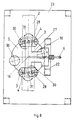
- the arrangement is particularly clear from FIG. 8.
- the reference openings 29 in FIG. 8 schematically indicate the through openings for the rollers (4).
- the four star screws (30) can also be found in FIG.
- the brackets (28) are rotatably mounted about the respective axis (31). In this way, the support can adapt to all curves and turns of the pipe run.
- a lubricant line (6) which is heated by the jacket, leads to the support (1) shown in FIG.
- a nozzle (16) is attached to the end of this lubricant line.
- FIG. 4 shows the upper part of the lubricating device, in particular the support in a view in the direction of arrow IV of FIG. 1.
- thermal insulation (32) is additionally drawn.
- Figure 5 shows a side view of the middle and lower part of the lubricating device in the direction of arrow V in Figure 1.
- the upper part of this drawing is shown enlarged in Figure 6.
- the bracket (5) is covered at the top by a mounting plate (17).
- the mounting plate (17) rests on a ring (33) and is separated from it by thermal insulation (34), which also runs inside the mounting plate (17).
- the mounting plate (17) has a downward cylindrical projection, into which a blind hole (18) with an internal thread (19) is incorporated, this blind hole (18) opening into a channel (20).
- the channel (20) connects the blind bore (18) to the lubricant line (6).
- the upper part of the holder (5) is heated by flat heating elements (15).
- FIG. 6 also shows a cartridge (8) with a cartridge casing (10) and a cartridge base (9).
- the check valve (7) in FIG. 7 is designed for an overpressure of 1 bar.
- the distance between the mounting plate (17) and the support (1) is about half a meter.
- the cartridge itself is also heated with flat heating elements (15).
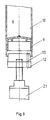
- Figures 9 and 10 show details of the piston (12).
- the piston (12) has the shape of a truncated cone with the more pointed end in the direction of the cartridge base (9).
- the plastic piston (12) is provided with a bore (13) which runs parallel to the longitudinal axis but offset laterally to it.
- cartridges filled with grease can be expressed when heated and this grease can be applied to pipes through a pipe system using a nozzle.
- aluminum cartridges with a content of 0.3 liters are screwed into the thread (19) of the mounting plate (17).
- the mounting plate (17), the riser pipe (6) and the nozzle holder are heated to 60 to 70 ° C by flexible silicone heaters.
- the temperature monitoring is carried out by a control unit (14) with four measuring points.
- the nozzle (16) is arranged such that it is in operation 2 mm above the tube track.
- the brackets (28) can be swiveled by 90 °, so that even very narrow pipe track curves can be driven.
Landscapes
- Engineering & Computer Science (AREA)
- Mechanical Engineering (AREA)
- Coating Apparatus (AREA)
- Lubricants (AREA)
- Fats And Perfumes (AREA)
- Earth Drilling (AREA)
- Supports For Pipes And Cables (AREA)
- Bending Of Plates, Rods, And Pipes (AREA)
- Metal Extraction Processes (AREA)
Description
- Solche Rohrbahnen finden sich als Transportsystem z.B. in Schlachtereien und der fleischverarbeitenden Industrie. Unter Rohrbahnen sind hier Schienen-, Träger- oder Rohrsysteme zu verstehen, an denen das Transportgut, z.B. Fleisch an Gleithaken hängend transportiert wird. Eine Schmierung dieser Gleitbahnen ist notwendig, um die manuelle oder maschinelle Bewegung der schweren Gehänge, auch über lange Strecken, zu erleichtern. Die Schmierung sollte schnell erfolgen und auch während des laufenden Betriebs möglich sein.
- Diese Aufgabe wird erfindungsgemäß bei einem mobilen Schmiergerät für Rohrbahnen durch die folgenden Merkmale gelöst:
Es sind eine Auflagerung, die das Halten und Führen des Schmiergeräts mittels einer Rohrbahn während des Schmiervorgangs ermöglicht und die mindestens zwei um eine etwa vertikale Achse und unabhängig voneinander drehbare Lager für Rollen aufweist, eine unterhalb der Auflagerung angeordnete Halterung für einen Schmierstoff-Vorratsbehälter und eine von der Halterung zur Auflagerung führende Schmierstoffleitung mit einer Düse an derem Ende vorgesehen. - Das Schmiergerät kann also während des Schmiervorgangs über das Transportsystem hin- und hergeschoben werden. Vor und nach dem Schmieren kann das Schmiergerät ebenfalls über das schon vorhandene Transportsystem bewegt werden. Durch die oben genannten Lager kann das Gerät auch enge Kurven fahren. Da die Halterung unterhalb der Auflagerung vorgesehen ist, kann das Schmiergerät auch zum Schmieren von dicht unterhalb der Decke angeordneten Transportbahnen eingesetzt werden.
- Vorteilhaft ist weiterhin ein Rückschlagventil an dem unteren Ende der Schmierstoffleitung. Dadurch wird verhindert, daß bei einem Wechsel des Schmierstoff-Vorratsbehälters der in der Schmierstoff-Leitung noch befindliche restliche Schmierstoff ausfließt.
- Weiterhin ist es vorteilhaft, wenn die Halterung für eine Schmierstoff enthaltende Kartusche ausgelegt ist, die durch Hineinschieben des Kartuschenbodens in den Kartuschenmantel entleerbar ist, und wenn ein von einem Antrieb axial bewegbarer kegelstumpfförmiger Kolben mit dem spitzeren Ende zum Hineinschieben des Kartuschenbodens vorgesehen ist. Zum einen wird bei dieser Anordnung der Schmierstoff kontinuierlich der Düse zugeführt. Zum anderen bewirkt die Kegelstumpfform des Kolbens, daß er den Kartuschenboden gegen die Innenseite des Kartuschenmantels drückt und damit der Zwischenraum zwischen Kartuschenboden und Kartuschenmantel wie mit einer Dichtung abgedichtet ist, so daß auch bei höheren, auf den Kartuschenboden wirkenden Drücken kein Schmierstoff zwischen der Innenseite des Kartuschemantels und dem Kartuschenboden austreten kann.
- In diesem Fall ist eine besonders gute Abdichtung dadurch zu erreichen, daß der Kolben aus einem leicht verformbaren Material, insbesondere Kunststoff besteht. Der Kolben paßt sich dann nämlich besonders gut an die Form des Kartuschenbodens an. Auch ist die Herstellung eines solchen Kolbens preiswerter als die eines Metallkolbens.
- Um bei einem Rückfahren des Kolbens nach dem Entleeren der Kartusche den Kartuschenboden infolge des Saugeffektes nicht wieder zurückzuziehen, wird vorgeschlagen, daß eine beide ebenen Flächen des kegelstumpfförmigen Kolbens verbindende Bohrung vorgesehen wird. Diese Bohrung sorgt für den Druckausgleich.
- Um mit dem Schmiergerät auch bei Umgebungstemperaturen, insbesondere bei der relativ niedrigen Umgebungstemperatur der fleischverarbeitenden Industrie, festen Schmierstoff auftragen zu können, werden an eine Regelung angeschlossene Heizelemente zum Beheizen des Schmierstoff-Vorratsbehälters, der Schmierstoff-Leitung und der Düse vorgeschlagen. Ein besonderer Vorteil dieser Ausgestaltung liegt darin, daß der aus der Düse austretende heiße Schmierstoff durch die relativ kalte Rohrbahn sofort abgekühlt wird und daher auf dieser fest haftet. Es läßt sich daher ein gut haftender, harter Schmierstoff-Film auf der Rohrbahn erreichen.
- Um zum einen bei der Beheizung eine ausreichend hohe Temperatur des Schmierstoffs zu erreichen, so daß er auf der Rohrbahn gut haftet, und zum anderen den Schmierstoff nicht zu hoch zu erhitzen, so daß er sich chemisch verändert, wird vorgeschlagen, daß die Regelung zum Regeln der Temperatur mit einer Regelabweichung von höchstens 5 °C und insbesonders zum Regeln auf 60 - 70 °C ausgelegt ist. Dieser letztere Temperaturbereich hat sich als besonders günstig bewährt.
- Um während des Schmierens von Energieversorgungskabeln unabhängig zu sein, wird ein als Energieversorgung dienender Akkumulator vorgeschlagen, sowie ein Fahrtisch, mit dem der Akkumulator transportierbar ist, und ein Stromversorgungskabel zwischen Akkumulator und dem an die Rohrbahn hängbaren Teil des Schmiergerätes.
- Ein schneller Wechsel der Schmierstoff-Kartusche wird durch eine Befestigungsplatte mit einer zentralen Sackbohrung ermöglicht, die ein an das Gewinde der Kartusche angepaßtes Innengewinde aufweist und mit ihrem toten Ende an einen Kanal innerhalb der Befestigungsplatte angeschlossen ist. Durch diese Maßnahmen wird die Kartusche gleichzeitig gehaltert und an die Schmierstoffleitung angeschlossen. Bei einem Wechsel der Kartusche ist es nur notwendig, die Befestigungsplatte mit der daran hängenden leeren Kartusche aus dem Schmierstoffgerät zu entnehmen, die leere Kartusche abzuschrauben, eine neue Kartusche einzuschrauben, und die Befestigungsplatte mit der nun gefüllten Kartusche wieder an das Schmierstoffgerät zu befestigen. Die Befestigung der Befestigungsplatte selbst kann vorteilhaft durch Schrauben geschehen.
- Eine preiswerte, gut austauschbare Düse wird dadurch erhalten, daß die Düse als ein längs gebohrter, in das Ende der Schmierstoff-Leitung einschraubbarer Gewindestift ausgebildet ist.
- Eine einstellbare, genau kontrollierbare Dosierung des Schmierstoffes wird durch einen von einer Einachs-Positioniersteuerung gesteuerten, den Kolben betätigenden Hubzylinder erreicht.
- Mit dem erfindungsgemäßen Schmiergerät lassen sich die Rohre an der Rohroberseite der Rohrbahn bei einer Umgebungstemperatur weit unter 0 °C durch manuelles Fortbewegen des Gerätes mit dem erhitzten Schmierstoff gleichmäßig schmieren. Der Schmierstoff wird schnell aufgebracht und die genau benötigte Menge kann dosiert werden. Nach dem Auftragen liegt der Schmierstoff wegen des großen Unterschiedes zwischen der Beheizungstemperatur und der Temperatur der Rohrbahn als glatter, gut haftender und nicht tropfender Film vor, so daß bei allen Transportarbeiten, insbesondere in der fleischverarbeitenden Industrie die Fleischqualität unbeeinträchtigt bleibt.
- Zum Stand der Technik wird die DE-OS 36 32 948 genannt.
- Nachstehend wird eine spezielle Ausführungsform der Erfindung anhand der Zeichnungen näher erläutert. Es zeigen:
- Figur 1:
- eine Ausführung des erfindungsgemäßen Schmiergeräts in einer seitlichen Ansicht,
- Figur 2:
- einen Schnitt durch eine Rohrbahn,
- Figur 3:
- eine Vergrößerung des in Figur 1 dargestellten oberen Teils,
- Figur 4:
- eine Ansicht des oberen Teils von Figur 1 in Richtung des Pfeils IV,
- Figur 5:
- eine Ansicht des unteren Teils von Figur 1 in Richtung des Pfeils V, wobei die Kartuschenhalterung und die damit verbundenen Teile im Schnitt dargestellt sind,
- Figur 6:
- eine Vergrößerung des oberen Teils von Figur 5,
- Figur 7:
- eine Vergrößerung des mittleren Teils von Figur 1,
- Figur 8:
- eine Aufsicht von oben auf das Schmiergerät,
- Figur 9:
- einen Schnitt durch den Kolben, den Hubzylinder und das Kartuschenende und
- Figur 10:
- eine Aufsicht auf den Kolben.
- Figur 1 zeigt eine Ansicht eines erfindungsgemäßen Schmiergerätes. Es besteht hauptsächlich aus drei Einheiten. Die erste Einheit befindet sich räumlich oben und ist aus der Auflagerung (1), die auf der Rohrbahn (2) ruht, der mit der Auflagerung (1) verbundenen Strebenkonstruktion (22) und der Schmierstoff-Leitung (6) zusammengesetzt. In mittlerer Höhe des Schmiergerätes befindet sich die Halterung (5) für den Schmierstoff-Vorratsbehälter, der an die Schmierstoff-Leitung (6) angeschlossen ist. Dieser Halterungsteil ist an einem Gestell (23) befestigt. In diesem Gestell sind im wesentlichen der Antrieb (11) für den vom Hubzylinder (21) betätigten Kolben und die Regelung (14) eingebaut.
- Das Auflagerungsproblem des Schmiergerätes wird besonders deutlich aus Figur 2. Ein Rohr (24) einer Rohrbahn ist mittels mehrerer L-Stücke (25) an der Decke (26) befestigt. Das Rohr (24) hat gemäß Figur 3 nur einen sehr geringen Abstand von der Decke (26) sowie vom L-Stück (25). Dieser Umstand ist wie nachfolgend beschrieben berücksichtigt worden. In Figur 2 sind zusätzlich und schematisch die Rollen (4) der Auflagerung (1) eingezeichnet. Typischerweise betragen die Abstände des Rohrs (24) zur Decke und zum L-Stück nur etwa 25 mm.
- In Figur 3 ist eine Vergrößerung des oberen Teils von Figur 1 dargestellt. Am waagerechten Arm (27), der an seiner Unterseite ein flaches Heizelement (15) trägt, ist ein nach unten gebogener Bügel (28) befestigt. Der Bügel (28) hält vier drehbare Lager (3) für Rollen (4), von denen nur zwei in Figur 3 erkennbar sind. Die Anordnung wird besonders deutlich aus Figur 8. Beim Bezugszeichen 29 in Figur 8 sind die Durchtrittsöffnungen für die Rollen (4) schematisch angedeutet. Zusätzlich finden sich noch in Figur 8 die vier Sternschrauben (30). Die Bügel (28) sind um die jeweilige Achse (31) drehbar gelagert. So kann sich die Auflagerung allen Kurven und Windungen der Rohrbahn anpassen.
- Zu der in Figur 3 dargestellten Auflagerung (1) führt eine Schmierstoffleitung (6), die mantelbeheizt ist. Am Ende dieser Schmierstoffleitung ist eine Düse (16) angebracht.
- Figur 4 zeigt den oberen Teil des Schmiergerätes, insbesondere also die Auflagerung in einer Ansicht in Richtung des Pfeiles IV von Figur 1. Auch hier, wie in allen Figuren, werden für gleiche Teile gleiche Bezugszeichen verwendet. In Figur 3 wie auch in Figur 4 ist zusätzlich eine Wärmeisolierung (32) eingezeichnet.
- Figur 5 zeigt eine Seitenansicht des mittleren und unteren Teils des Schmiergerätes in Richtung des Pfeiles V in Figur 1. Der obere Teil dieser Zeichnung ist in Figur 6 vergrößert dargestellt. Die Halterung (5) wird oben von einer Befestigungsplatte (17) abgedeckt. Die Befestigungsplatte (17) liegt auf einem Ring (33) auf und ist von dieser durch eine Wärmeisolierung (34) getrennt, die auch innerhalb der Befestigungsplatte (17) verläuft. Die Befestigungsplatte (17) weist einen nach unten gerichteten zylindrischen Vorsprung auf, in den eine Sackbohrung (18) mit einem Innengewinde (19) eingearbeitet ist, wobei diese Sackbohrung (18) in einen Kanal (20) mündet. Der Kanal (20) verbindet, wie in Figur 7 besonders deutlich sichtbar, die Sackbohrung (18) mit der Schmierstoffleitung (6). Zwischen dem Ausgang des Kanals (20) und der Schmierstoffleitung (6) ist noch ein Rückschlagventil (7) angeordnet. Der obere Teil der Halterung (5) wird über flächige Heizelemente (15) beheizt.
- In Figur 6 ist ferner eine Kartusche (8) mit einem Kartuschenmantel (10) und einem Kartuschenboden (9) eingezeichnet. Auf den Kartuschenboden (9) drückt ein Kolben (12), der in Figur 6 nur schematisch und in Figur 9 und 10 genauer dargestellt ist.
- Das Rückschlagventil (7) in Figur 7 ist auf einen Überdruck von 1 bar ausgelegt. Der Abstand zwischen der Befestigungsplatte (17) und der Auflagerung (1) beträgt etwa einen halben Meter. Auch die Kartusche selbst wird mit flächigen Heizelementen (15) beheizt.
- Die Figuren 9 und 10 zeigen Details des Kolbens (12). Der Kolben (12) hat die Form eines Kegelstumpfes mit dem spitzeren Ende in Richtung des Kartuschenbodens (9). Zum Ausgleich des Luftdrucks ist der aus Kunststoff bestehende Kolben (12) mit einer Bohrung (13) versehen, die parallel zur Längsachse, aber seitlich versetzt dazu verläuft.
- Mit diesem Schmiergerät können mit Fett gefüllte Kartuschen im erwärmten Zustand ausgedrückt und dieses Fett durch ein Leitungssystem mittels einer Düse auf Rohrleitungen aufgetragen werden. Dazu werden Aluminiumkartuschen mit einem Inhalt von 0,3 Liter in das Gewinde (19) der Befestigungsplatte (17) geschraubt. Die Befestigungsplatte (17), das Steigrohr (6), sowie die Düsenhalterung werden durch flexible Silikon-Heizungen auf 60 bis 70 °C aufgeheizt. Die Temperaturüberwachung nimmt eine Regeleinheit (14) mit vier Meßstellen vor. Die Düse (16) ist derart angeordnet, daß sie sich im Betrieb 2 mm über der Rohrbahn befindet. Im Ausführungsbeispiel sind die Bügel (28) um 90 ° schwenkbar, so daß auch sehr enge Rohrbahn-Kurven gefahren werden können.
- Mit diesem Rohrbahn-Schmiergerät lassen sich 0,3 Liter, also der gesamte Inhalt einer Kartusche in etwa 6 Minuten gleichmäßig auf die Rohrbahn auftragen.
-
- 1
- Auflagerung
- 2
- Rohrbahn
- 3
- Lager
- 4
- Rollen
- 5
- Halterung
- 6
- Schmierstoff-Leitung
- 7
- Rückschlagventil
- 8
- Kartusche
- 9
- Kartuschenboden
- 10
- Kartuschenmantel
- 11
- Antrieb
- 12
- Kolben
- 13
- Bohrung
- 14
- Regelung
- 15
- Heizelemente
- 16
- Düse
- 17
- Befestigungsplatte
- 18
- Sackbohrung
- 19
- Innengewinde
- 20
- Kanal
- 21
- Hubzylinder
- 22
- Strebenkonstruktion
- 23
- Gestell
- 24
- Rohr
- 25
- L-Stück
- 26
- Decke
- 27
- Arm
- 28
- Bügel
- 30
- Sternschrauben
- 31
- Achse
- 32
- Wärmeisolierung
- 33
- Ring
- 34
- Wärmeisolierung
Claims (11)
- Mobiles Schmiergerät für Rohrbahnen,
gekennzeichnet durch
eine Auflagerung (1), die das Halten und Führen des Schmiergeräts mittels einer Rohrbahn (2) während des Schmiervorgangs ermöglicht und die mindestens zwei um eine etwa vertikale Achse und unabhängig voneinander drehbare Lager (3) für Rollen (4) aufweist, eine unterhalb der Auflagerung (1) angeordnete Halterung (5) für einen Schmierstoff-Vorratsbehälter und eine von der Halterung (5) zur Auflagerung (1) führende Schmierstoff-Leitung (6) mit einer Düse (16) an derem Ende. - Schmiergerät nach Anspruch 1,
gekennzeichnet durch
ein Rückschlagventil (7) an dem unteren Ende der Schmierstoff-Leitung (6). - Schmiergerät nach Anspruch 1 oder 2,
dadurch gekennzeichnet,
daß die Halterung (5) für eine Schmierstoff enthaltende Kartusche (8) ausgelegt ist, die durch Hineinschieben des Kartuschenbodens (9) in den Kartuschenmantel (10) entleerbar ist, daß ein von einem Antrieb (11) axial bewegbarer kegelstumpfförmiger Kolben (12) mit dem spitzeren Ende zum Hineinschieben des Kartuschenbodens (9) vorgesehen ist. - Schmiergerät nach Anspruch 3,
dadurch gekennzeichnet,
daß der Kolben (12) aus einem leicht verformbaren Material, insbesondere Kunststoff besteht. - Schmiergerät nach Anspruch 3 oder 4,
gekennzeichnet durch
eine beide ebenen Flächen des kegelstumpfförmigen Kolbens (12) verbindende Bohrung (13). - Schmiergerät nach einem der Ansprüche 1 bis 5,
gekennzeichnet durch
an eine Regelung (14) angeschlossene Heizelemente (15) zum Beheizen des Schmierstoff-Vorratsbehälters, der Schmierstoff-Leitung (6) und der Düse (16). - Schmiergerät nach Anspruch 6,
dadurch gekennzeichnet,
daß die Regelung (14) zum Regeln der Temperatur mit einer Regelabweichung von höchstens 5 °C und insbesonders zum Regeln auf 60 bis 70 °C ausgelegt ist. - Schmiergerät nach einem der Ansprüche 1 bis 7,
gekennzeichnet durch
einen als Energieversorgung dienenden Akkumulator, einen Fahrtisch, mit dem der Akkumulator transportierbar ist, und ein Stromversorgungskabel zwischen Akkumulator und dem an die Rohrbahn (2) hängbaren Teil des Schmiergerätes. - Schmiergerät nach einem der Ansprüche 3 bis 8,
gekennzeichnet durch
eine Befestigungsplatte (17) mit einer zentralen Sackbohrung (18), die ein an das Gewinde der Kartusche (8) angepaßtes Innengewinde (19) aufweist und mit ihrem toten Ende an einen Kanal (20) innerhalb der Befestigungsplatte (17) angeschlossen ist. - Schmiergerät nach einem der Ansprüche 1 bis 9,
dadurch gekennzeichnet,
daß die Düse (16) als ein längs gebohrter, in das Ende der Schmierstoff-Leitung (6) einschraubbarer Gewindestift ausgebildet ist. - Schmiergerät nach einem der Ansprüche 3 bis 10,
gekennzeichnet durch
einen von einer Einachs-Positioniersteuerung gesteuerten, den Kolben (12) betätigenden Hubzylinder (21).
Applications Claiming Priority (3)
| Application Number | Priority Date | Filing Date | Title |
|---|---|---|---|
| DE3925653A DE3925653A1 (de) | 1989-08-03 | 1989-08-03 | Mobiles schmiergeraet fuer rohrbahnen |
| DE3925653 | 1989-08-03 | ||
| PCT/EP1990/001213 WO1991001931A1 (de) | 1989-08-03 | 1990-07-25 | Mobiles schmiergerät für rohrbahnen |
Publications (2)
| Publication Number | Publication Date |
|---|---|
| EP0485402A1 EP0485402A1 (de) | 1992-05-20 |
| EP0485402B1 true EP0485402B1 (de) | 1994-04-20 |
Family
ID=6386409
Family Applications (1)
| Application Number | Title | Priority Date | Filing Date |
|---|---|---|---|
| EP90910633A Expired - Lifetime EP0485402B1 (de) | 1989-08-03 | 1990-07-25 | Mobiles schmiergerät für rohrbahnen |
Country Status (6)
| Country | Link |
|---|---|
| EP (1) | EP0485402B1 (de) |
| AT (1) | ATE104639T1 (de) |
| DE (2) | DE3925653A1 (de) |
| DK (1) | DK0485402T3 (de) |
| ES (1) | ES2051520T3 (de) |
| WO (1) | WO1991001931A1 (de) |
Families Citing this family (2)
| Publication number | Priority date | Publication date | Assignee | Title |
|---|---|---|---|---|
| DE10323810B3 (de) * | 2003-05-23 | 2004-11-18 | Hs Klebtec Klebetechnik Und Sondermaschinen Gmbh | Vorrichtung zum Auftragen von Klebstoff |
| CN113983049B (zh) * | 2021-11-16 | 2023-09-08 | 惠州市联创丽声电子有限公司 | 自动打胶保压装置 |
Family Cites Families (3)
| Publication number | Priority date | Publication date | Assignee | Title |
|---|---|---|---|---|
| GB928248A (en) * | 1960-09-17 | 1963-06-12 | Gustav Mohring | Improvements relating to the lubrication of chain guides |
| FI52205C (fi) * | 1976-03-17 | 1977-07-11 | Safematic Ltd Oy | Voitelujärjestelmä kuljetinrataa varten. |
| DE3632948A1 (de) * | 1986-09-27 | 1988-03-31 | Lang Apparatebau Gmbh | Kartuschenauspressvorrichtung |
-
1989
- 1989-08-03 DE DE3925653A patent/DE3925653A1/de not_active Withdrawn
-
1990
- 1990-07-25 DE DE59005471T patent/DE59005471D1/de not_active Expired - Fee Related
- 1990-07-25 EP EP90910633A patent/EP0485402B1/de not_active Expired - Lifetime
- 1990-07-25 WO PCT/EP1990/001213 patent/WO1991001931A1/de not_active Ceased
- 1990-07-25 DK DK90910633.8T patent/DK0485402T3/da active
- 1990-07-25 ES ES90910633T patent/ES2051520T3/es not_active Expired - Lifetime
- 1990-07-25 AT AT9090910633T patent/ATE104639T1/de not_active IP Right Cessation
Also Published As
| Publication number | Publication date |
|---|---|
| DK0485402T3 (da) | 1994-10-10 |
| DE59005471D1 (de) | 1994-05-26 |
| WO1991001931A1 (de) | 1991-02-21 |
| ATE104639T1 (de) | 1994-05-15 |
| ES2051520T3 (es) | 1994-06-16 |
| DE3925653A1 (de) | 1991-02-07 |
| EP0485402A1 (de) | 1992-05-20 |
Similar Documents
| Publication | Publication Date | Title |
|---|---|---|
| DE19754454B4 (de) | Schmierölzufuhrsystem für Rollführungsvorrichtung | |
| EP0551457A1 (de) | Schleifgerät zum schleifen einer zylindrischen oder sphärischen oberfläche einer walze, insbesondere einer walze einer papiermaschine. | |
| DE2461495A1 (de) | Einrichtung zum zurichten von streifen unterschiedlicher breite | |
| DE1652535C3 (de) | Schmiereinrichtung für ein Rohrwalzwerk | |
| DE1299097B (de) | Vorrichtung zum Schneiden einer Glasplatte | |
| EP0625389B1 (de) | Giessgarnitur für eine Druckgiessmaschine | |
| DE69428374T2 (de) | Kontakt-lubrikator mit bemessener zufuhr | |
| DE1504537A1 (de) | Einrichtung zum Orientieren eines schlauchfoermigen Erzeugnisses laengs zweier Achsen | |
| DE3438041C2 (de) | Luftmesser-Beschichter | |
| WO1991001931A1 (de) | Mobiles schmiergerät für rohrbahnen | |
| DE2625850A1 (de) | Geraet zum foerdern von druckfarbe zu einer druckeinrichtung | |
| WO2003012306A1 (de) | Linearwälzlagerelement | |
| DE2822248C2 (de) | Führungslager für eine verschiebbare Formaufspannplatte | |
| EP0405387B1 (de) | Verfahren und Vorrichtung zum Pressen hohler Formlinge aus Glas | |
| DE2710559B2 (de) | Schmieranordnung für eine Transportvorrichtung | |
| DE19506320C1 (de) | Kalander | |
| DE3636446C2 (de) | Gewindemuffeneinschraubvorrichtung | |
| DE2208676A1 (de) | Kabelführungsvorrichtung | |
| DE4239768C2 (de) | Vorrichtung zum Erfassen und Transportieren von Werkzeugen | |
| EP2161113A1 (de) | Automatische Schmierung | |
| DE2953645A1 (de) | Steuereinrichtung fuer zentralschmiersystem | |
| DE1814736B1 (de) | Vorrichtung fuer die betriebliche Unterhaltung von Foerderband-Stuetzrollen | |
| DE69523616T2 (de) | Vorrichtung zur verbesserung der gleiteigenschaften eines metaldrahtes | |
| DE6811334U (de) | Vorrichtung zum schmieren von waelzlagern | |
| EP0220365B1 (de) | Vorrichtung zum automatischen Benetzen des Wulstfusses von Fahrzeugreifen aus Gummi mit einem Benetzungsmedium |
Legal Events
| Date | Code | Title | Description |
|---|---|---|---|
| PUAI | Public reference made under article 153(3) epc to a published international application that has entered the european phase |
Free format text: ORIGINAL CODE: 0009012 |
|
| 17P | Request for examination filed |
Effective date: 19920127 |
|
| AK | Designated contracting states |
Kind code of ref document: A1 Designated state(s): AT BE CH DE DK ES FR GB IT LI LU NL SE |
|
| 17Q | First examination report despatched |
Effective date: 19930615 |
|
| GRAA | (expected) grant |
Free format text: ORIGINAL CODE: 0009210 |
|
| AK | Designated contracting states |
Kind code of ref document: B1 Designated state(s): AT BE CH DE DK ES FR GB IT LI LU NL SE |
|
| REF | Corresponds to: |
Ref document number: 104639 Country of ref document: AT Date of ref document: 19940515 Kind code of ref document: T |
|
| REF | Corresponds to: |
Ref document number: 59005471 Country of ref document: DE Date of ref document: 19940526 |
|
| GBT | Gb: translation of ep patent filed (gb section 77(6)(a)/1977) |
Effective date: 19940504 |
|
| REG | Reference to a national code |
Ref country code: ES Ref legal event code: FG2A Ref document number: 2051520 Country of ref document: ES Kind code of ref document: T3 |
|
| ET | Fr: translation filed | ||
| ITF | It: translation for a ep patent filed | ||
| EPTA | Lu: last paid annual fee | ||
| REG | Reference to a national code |
Ref country code: DK Ref legal event code: T3 |
|
| EAL | Se: european patent in force in sweden |
Ref document number: 90910633.8 |
|
| PLBE | No opposition filed within time limit |
Free format text: ORIGINAL CODE: 0009261 |
|
| STAA | Information on the status of an ep patent application or granted ep patent |
Free format text: STATUS: NO OPPOSITION FILED WITHIN TIME LIMIT |
|
| 26N | No opposition filed | ||
| PGFP | Annual fee paid to national office [announced via postgrant information from national office to epo] |
Ref country code: SE Payment date: 19980707 Year of fee payment: 9 |
|
| PGFP | Annual fee paid to national office [announced via postgrant information from national office to epo] |
Ref country code: FR Payment date: 19980709 Year of fee payment: 9 |
|
| PGFP | Annual fee paid to national office [announced via postgrant information from national office to epo] |
Ref country code: DK Payment date: 19980713 Year of fee payment: 9 Ref country code: AT Payment date: 19980713 Year of fee payment: 9 |
|
| PGFP | Annual fee paid to national office [announced via postgrant information from national office to epo] |
Ref country code: GB Payment date: 19980716 Year of fee payment: 9 |
|
| PGFP | Annual fee paid to national office [announced via postgrant information from national office to epo] |
Ref country code: LU Payment date: 19980720 Year of fee payment: 9 |
|
| PGFP | Annual fee paid to national office [announced via postgrant information from national office to epo] |
Ref country code: NL Payment date: 19980728 Year of fee payment: 9 |
|
| PGFP | Annual fee paid to national office [announced via postgrant information from national office to epo] |
Ref country code: DE Payment date: 19980803 Year of fee payment: 9 |
|
| PGFP | Annual fee paid to national office [announced via postgrant information from national office to epo] |
Ref country code: CH Payment date: 19980806 Year of fee payment: 9 |
|
| PGFP | Annual fee paid to national office [announced via postgrant information from national office to epo] |
Ref country code: BE Payment date: 19980914 Year of fee payment: 9 |
|
| PGFP | Annual fee paid to national office [announced via postgrant information from national office to epo] |
Ref country code: ES Payment date: 19990719 Year of fee payment: 10 |
|
| PG25 | Lapsed in a contracting state [announced via postgrant information from national office to epo] |
Ref country code: LU Free format text: LAPSE BECAUSE OF NON-PAYMENT OF DUE FEES Effective date: 19990725 Ref country code: GB Free format text: LAPSE BECAUSE OF NON-PAYMENT OF DUE FEES Effective date: 19990725 Ref country code: AT Free format text: LAPSE BECAUSE OF NON-PAYMENT OF DUE FEES Effective date: 19990725 |
|
| PG25 | Lapsed in a contracting state [announced via postgrant information from national office to epo] |
Ref country code: SE Free format text: THE PATENT HAS BEEN ANNULLED BY A DECISION OF A NATIONAL AUTHORITY Effective date: 19990726 |
|
| PG25 | Lapsed in a contracting state [announced via postgrant information from national office to epo] |
Ref country code: LI Free format text: LAPSE BECAUSE OF NON-PAYMENT OF DUE FEES Effective date: 19990731 Ref country code: FR Free format text: THE PATENT HAS BEEN ANNULLED BY A DECISION OF A NATIONAL AUTHORITY Effective date: 19990731 Ref country code: CH Free format text: LAPSE BECAUSE OF NON-PAYMENT OF DUE FEES Effective date: 19990731 Ref country code: BE Free format text: LAPSE BECAUSE OF NON-PAYMENT OF DUE FEES Effective date: 19990731 |
|
| PG25 | Lapsed in a contracting state [announced via postgrant information from national office to epo] |
Ref country code: DK Free format text: LAPSE BECAUSE OF NON-PAYMENT OF DUE FEES Effective date: 19990802 |
|
| BERE | Be: lapsed |
Owner name: HENKEL K.G.A.A. Effective date: 19990731 |
|
| PG25 | Lapsed in a contracting state [announced via postgrant information from national office to epo] |
Ref country code: NL Free format text: LAPSE BECAUSE OF NON-PAYMENT OF DUE FEES Effective date: 20000201 |
|
| GBPC | Gb: european patent ceased through non-payment of renewal fee |
Effective date: 19990725 |
|
| REG | Reference to a national code |
Ref country code: CH Ref legal event code: PL |
|
| REG | Reference to a national code |
Ref country code: DK Ref legal event code: EBP |
|
| EUG | Se: european patent has lapsed |
Ref document number: 90910633.8 |
|
| NLV4 | Nl: lapsed or anulled due to non-payment of the annual fee |
Effective date: 20000201 |
|
| PG25 | Lapsed in a contracting state [announced via postgrant information from national office to epo] |
Ref country code: DE Free format text: LAPSE BECAUSE OF NON-PAYMENT OF DUE FEES Effective date: 20000503 |
|
| REG | Reference to a national code |
Ref country code: FR Ref legal event code: ST |
|
| PG25 | Lapsed in a contracting state [announced via postgrant information from national office to epo] |
Ref country code: ES Free format text: LAPSE BECAUSE OF NON-PAYMENT OF DUE FEES Effective date: 20000726 |
|
| REG | Reference to a national code |
Ref country code: ES Ref legal event code: FD2A Effective date: 20010810 |
|
| PG25 | Lapsed in a contracting state [announced via postgrant information from national office to epo] |
Ref country code: IT Free format text: LAPSE BECAUSE OF NON-PAYMENT OF DUE FEES;WARNING: LAPSES OF ITALIAN PATENTS WITH EFFECTIVE DATE BEFORE 2007 MAY HAVE OCCURRED AT ANY TIME BEFORE 2007. THE CORRECT EFFECTIVE DATE MAY BE DIFFERENT FROM THE ONE RECORDED. Effective date: 20050725 |