EP0484697A2 - Méthode de commande semi-active d'une suspension - Google Patents
Méthode de commande semi-active d'une suspension Download PDFInfo
- Publication number
- EP0484697A2 EP0484697A2 EP91117528A EP91117528A EP0484697A2 EP 0484697 A2 EP0484697 A2 EP 0484697A2 EP 91117528 A EP91117528 A EP 91117528A EP 91117528 A EP91117528 A EP 91117528A EP 0484697 A2 EP0484697 A2 EP 0484697A2
- Authority
- EP
- European Patent Office
- Prior art keywords
- valve
- wheel
- damper
- movement
- piston
- Prior art date
- Legal status (The legal status is an assumption and is not a legal conclusion. Google has not performed a legal analysis and makes no representation as to the accuracy of the status listed.)
- Granted
Links
Images
Classifications
-
- B—PERFORMING OPERATIONS; TRANSPORTING
- B60—VEHICLES IN GENERAL
- B60G—VEHICLE SUSPENSION ARRANGEMENTS
- B60G17/00—Resilient suspensions having means for adjusting the spring or vibration-damper characteristics, for regulating the distance between a supporting surface and a sprung part of vehicle or for locking suspension during use to meet varying vehicular or surface conditions, e.g. due to speed or load
- B60G17/06—Characteristics of dampers, e.g. mechanical dampers
- B60G17/08—Characteristics of fluid dampers
-
- B—PERFORMING OPERATIONS; TRANSPORTING
- B60—VEHICLES IN GENERAL
- B60G—VEHICLE SUSPENSION ARRANGEMENTS
- B60G17/00—Resilient suspensions having means for adjusting the spring or vibration-damper characteristics, for regulating the distance between a supporting surface and a sprung part of vehicle or for locking suspension during use to meet varying vehicular or surface conditions, e.g. due to speed or load
- B60G17/015—Resilient suspensions having means for adjusting the spring or vibration-damper characteristics, for regulating the distance between a supporting surface and a sprung part of vehicle or for locking suspension during use to meet varying vehicular or surface conditions, e.g. due to speed or load the regulating means comprising electric or electronic elements
- B60G17/018—Resilient suspensions having means for adjusting the spring or vibration-damper characteristics, for regulating the distance between a supporting surface and a sprung part of vehicle or for locking suspension during use to meet varying vehicular or surface conditions, e.g. due to speed or load the regulating means comprising electric or electronic elements characterised by the use of a specific signal treatment or control method
-
- B—PERFORMING OPERATIONS; TRANSPORTING
- B60—VEHICLES IN GENERAL
- B60G—VEHICLE SUSPENSION ARRANGEMENTS
- B60G2400/00—Indexing codes relating to detected, measured or calculated conditions or factors
- B60G2400/10—Acceleration; Deceleration
- B60G2400/102—Acceleration; Deceleration vertical
-
- B—PERFORMING OPERATIONS; TRANSPORTING
- B60—VEHICLES IN GENERAL
- B60G—VEHICLE SUSPENSION ARRANGEMENTS
- B60G2400/00—Indexing codes relating to detected, measured or calculated conditions or factors
- B60G2400/20—Speed
-
- B—PERFORMING OPERATIONS; TRANSPORTING
- B60—VEHICLES IN GENERAL
- B60G—VEHICLE SUSPENSION ARRANGEMENTS
- B60G2400/00—Indexing codes relating to detected, measured or calculated conditions or factors
- B60G2400/20—Speed
- B60G2400/202—Piston speed; Relative velocity between vehicle body and wheel
-
- B—PERFORMING OPERATIONS; TRANSPORTING
- B60—VEHICLES IN GENERAL
- B60G—VEHICLE SUSPENSION ARRANGEMENTS
- B60G2400/00—Indexing codes relating to detected, measured or calculated conditions or factors
- B60G2400/50—Pressure
- B60G2400/51—Pressure in suspension unit
- B60G2400/518—Pressure in suspension unit in damper
- B60G2400/5182—Fluid damper
-
- B—PERFORMING OPERATIONS; TRANSPORTING
- B60—VEHICLES IN GENERAL
- B60G—VEHICLE SUSPENSION ARRANGEMENTS
- B60G2500/00—Indexing codes relating to the regulated action or device
- B60G2500/10—Damping action or damper
-
- B—PERFORMING OPERATIONS; TRANSPORTING
- B60—VEHICLES IN GENERAL
- B60G—VEHICLE SUSPENSION ARRANGEMENTS
- B60G2600/00—Indexing codes relating to particular elements, systems or processes used on suspension systems or suspension control systems
- B60G2600/18—Automatic control means
- B60G2600/184—Semi-Active control means
-
- B—PERFORMING OPERATIONS; TRANSPORTING
- B60—VEHICLES IN GENERAL
- B60G—VEHICLE SUSPENSION ARRANGEMENTS
- B60G2800/00—Indexing codes relating to the type of movement or to the condition of the vehicle and to the end result to be achieved by the control action
- B60G2800/01—Attitude or posture control
- B60G2800/012—Rolling condition
-
- B—PERFORMING OPERATIONS; TRANSPORTING
- B60—VEHICLES IN GENERAL
- B60G—VEHICLE SUSPENSION ARRANGEMENTS
- B60G2800/00—Indexing codes relating to the type of movement or to the condition of the vehicle and to the end result to be achieved by the control action
- B60G2800/24—Steering, cornering
-
- B—PERFORMING OPERATIONS; TRANSPORTING
- B60—VEHICLES IN GENERAL
- B60G—VEHICLE SUSPENSION ARRANGEMENTS
- B60G2800/00—Indexing codes relating to the type of movement or to the condition of the vehicle and to the end result to be achieved by the control action
- B60G2800/90—System Controller type
- B60G2800/91—Suspension Control
- B60G2800/912—Attitude Control; levelling control
Definitions
- the invention relates to a method for semi-active control of a chassis, in particular for damping resilient wheel suspension systems in vehicles according to the preamble of claim 1.
- an inertially guided damper which is installed between a fictitious rail running parallel above the road and the body, would be the ideal component.
- the present inventive method according to the characterizing part of claim 1 has the essential advantage that hydraulic decoupling of the compression and compression stages can be achieved by means of only one quickly adjustable valve. This one valve then also allows the valve arrangement to be integrated into the damper itself, as a result of which the space requirement for the valve arrangement is considerably reduced and components which are easier to install can be obtained.
- either the rebound or the compression stage of the damper must be set soft or hard for its optimal damping.
- This change in the valve position takes place according to the invention at the zero crossing of the relative speed of the relative movement between the wheel and the body or at the point in time at which the damper force is zero.
- the differential pressure on the damper piston which prevails between the upper and lower working chamber, can be taken as a parameter for this.
- the adjustment frequency is in the range of at least twice the natural wheel frequency.
- the method according to the invention also requires sensors which determine either the zero crossing of the relative speed of the body and the wheel or the zero crossing of the damper force, or else the zero crossing of the differential pressure on the damper piston.
- a corresponding control algorithm processes one of the signals mentioned together with the respective signal of the vertical speed of the body and controls the valves in a suitable manner via a power output stage of a control unit.
- the sensors required for the valve switching function can also be used for other functions at the same time.
- the relative speed can be calculated by differentiating the relative travel signal, the relative travel signal being able to be used simultaneously for level control systems or for the detection of load changes and the associated adjustments to the braking force distribution etc.
- valves can have different embodiments for the implementation of the present semi-active damper control concept.
- fast-switching valves which are available as throttle valves with two or more valve opening cross-sections for different pressure medium flows or as pressure-limiting valves with two or more pressure stages in pilot or direct operated designs, they are also continuously adjustable Throttle valves or pressure relief valves with high dynamic range can be used.
- the valves are traversed in the rebound and compression stages, whereby they must be able to vary their characteristics for each transition between this stage. This is a significant difference from the valves used in known control systems, since these are only designed as check valves.
- continuously adjustable valves When using continuously adjustable valves, it can also be striven for that the above-mentioned sensors not only detect the zero crossings directly, but rather supply current sensor values. Due to the extremely short cycle times of the control algorithm, the continuously adjustable valve is controlled at any time, thereby making optimal use of the engagement potential of this valve.
- the use of continuously adjustable valves allows an optimal wheel damping in contrast to a strong wheel damping with switching valves, whereby the optimal wheel damping refers to the minimization of dynamic wheel load fluctuations.
- control strategy required for the implementation of the method according to the invention is based on a closed control loop, which is suitably expanded by using threshold valves or gate function when using switching valves, the processing of the electrical sensor signals, the implementation of the control strategy and the control of the valves in an electrical control unit can be realized.
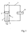
- the present semi-active chassis control relates above all to the control of shock absorbers 1, which are arranged between a structure (not shown in detail) and an axle or suspension of a wheel (also not shown in more detail).
- the shock absorber 1 consists of a cylinder 3, in which a damper piston 2 divides an upper working chamber 4 from a lower working chamber 5.
- a piston rod 6 leads from one of the working chambers 4, 5 and is connected to the damper piston 2.
- Upper working chamber 4 and lower working chamber 5 are connected to one another via a pressure medium line 7, into which a valve 8 is switched on.
- This valve 8 can be, for example, a fast-switching two-position or multi-position throttle valve, a pressure-limiting valve of a pilot-operated or direct-controlled type, or a continuously adjustable throttle valve or pressure-limiting valve. It is only essential that the valve reduce the flow of pressure medium in line 7 or increase the differential pressure at the valve, regardless of the direction in which the pressure medium flows between the two working chambers 4 and 5. Corresponding circuits of the valve can be described as hard or soft.
- the pressure medium line 7 can also be integrated in the damper piston 2 in series with the valve element 8.
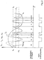
- damping force F D differential speed V rel between wheel and body and differential pressure ⁇ p are plotted on a time axis, this results in a sinusoidal movement, with the absolute speed of the body being drawn through in FIG. 2, the damper force F D dashed and the differential speed V rel between the wheel and body is shown in dash-dotted lines.
- the curve for the differential speed V rel corresponds to the curve for the differential pressure ⁇ p on the damper piston.
- Hard and soft (H, W) only apply in this form when switching valves are used. Continuously operating valves allow the hardness or softness to be nuanced depending on various parameters. When optimal wheel damping is taken into account at the same time as the body is calmed, additional criteria for optimal damping force adjustment on the body and wheel are superimposed on the switching law mentioned above.
- the threshold value of the body speed V0 is intended to prevent unnecessary damper force variations from occurring in the high-frequency range.
Landscapes
- Engineering & Computer Science (AREA)
- Mechanical Engineering (AREA)
- Vehicle Body Suspensions (AREA)
- Fluid-Damping Devices (AREA)
Applications Claiming Priority (2)
| Application Number | Priority Date | Filing Date | Title |
|---|---|---|---|
| DE4035314 | 1990-11-07 | ||
| DE4035314A DE4035314A1 (de) | 1990-11-07 | 1990-11-07 | Verfahren zum semiaktiven regeln eines fahrwerks |
Publications (3)
| Publication Number | Publication Date |
|---|---|
| EP0484697A2 true EP0484697A2 (fr) | 1992-05-13 |
| EP0484697A3 EP0484697A3 (en) | 1993-11-18 |
| EP0484697B1 EP0484697B1 (fr) | 1996-02-21 |
Family
ID=6417771
Family Applications (1)
| Application Number | Title | Priority Date | Filing Date |
|---|---|---|---|
| EP91117528A Expired - Lifetime EP0484697B1 (fr) | 1990-11-07 | 1991-10-15 | Méthode de commande semi-active d'une suspension |
Country Status (4)
| Country | Link |
|---|---|
| US (1) | US5324068A (fr) |
| EP (1) | EP0484697B1 (fr) |
| JP (1) | JPH05131825A (fr) |
| DE (2) | DE4035314A1 (fr) |
Cited By (5)
| Publication number | Priority date | Publication date | Assignee | Title |
|---|---|---|---|---|
| FR2676400A1 (fr) * | 1991-05-17 | 1992-11-20 | Atsugi Unisia Corp | Amortisseur de vehicule a coefficient reglable d'amortissement et procede de reglage. |
| FR2699455A1 (fr) * | 1992-12-18 | 1994-06-24 | Bosch Gmbh Robert | Procédé et dispositif pour la régulation et/ou la commande du mécanisme de roulement d'un véhicule automobile. |
| EP0739766A3 (fr) * | 1995-04-27 | 1998-02-04 | The Lubrizol Corporation | Procédé de contrÔle d'un mouvement utilisant un amortisseur réglable |
| DE102009023419A1 (de) * | 2009-05-29 | 2010-12-02 | Trw Automotive Gmbh | Semi-aktives hydraulisches Fahrwerksystem sowie Steuerungsverfahren für ein semi-aktives hydraulisches Fahrwerkstabilisierungssystem |
| CN103926947A (zh) * | 2014-04-16 | 2014-07-16 | 梁燕军 | 大跨度索桥结构非线性系统半主动振动控制方法 |
Families Citing this family (11)
| Publication number | Priority date | Publication date | Assignee | Title |
|---|---|---|---|---|
| JP3146927B2 (ja) * | 1994-08-08 | 2001-03-19 | トヨタ自動車株式会社 | 車両の減衰力制御装置 |
| US5588510A (en) * | 1995-09-25 | 1996-12-31 | Husco International, Inc. | Variable damping force shock absorber |
| US6097999A (en) * | 1998-06-12 | 2000-08-01 | General Motors Corporation | Vehicle suspension control system and method |
| US7684911B2 (en) * | 2005-06-20 | 2010-03-23 | Gm Global Technology Operations, Inc. | Suspension control calibration integrity |
| US7747359B2 (en) * | 2005-06-20 | 2010-06-29 | Gm Global Technology Operations, Inc. | Vehicle state determination integrity |
| US7706941B2 (en) * | 2006-07-20 | 2010-04-27 | Gm Global Technology Operations, Inc. | Method and system for coordinating a vehicle stability control system with a suspension damper control sub-system |
| US7946163B2 (en) * | 2007-04-02 | 2011-05-24 | Penske Racing Shocks | Methods and apparatus for developing a vehicle suspension |
| DE102007051224A1 (de) * | 2007-10-26 | 2009-04-30 | Volkswagen Ag | Verfahren und Regelungssystem zur Regelung der Aufbaubewegung eines Fahrzeugs |
| DE102009000576B4 (de) * | 2009-02-03 | 2020-09-10 | Robert Bosch Gmbh | Verfahren sowie Vorrichtung zur Fahrwerkregelung eines Kraftfahrzeugs |
| DE102016216008A1 (de) * | 2016-08-25 | 2018-03-01 | Volkswagen Aktiengesellschaft | Verfahren zur Ansteuerung der Schwingungsdämpfer einer Radaufhängung |
| CN114658786A (zh) * | 2022-03-22 | 2022-06-24 | 常州纺织服装职业技术学院 | 核电站用大型液压阻尼器 |
Family Cites Families (9)
| Publication number | Priority date | Publication date | Assignee | Title |
|---|---|---|---|---|
| JPS61163011A (ja) * | 1985-01-14 | 1986-07-23 | Nissan Motor Co Ltd | 電子制御ショックアブソ−バ装置 |
| DE3524862A1 (de) * | 1985-04-12 | 1986-10-30 | Robert Bosch Gmbh, 7000 Stuttgart | Vorrichtung zur daempfung von bewegungsablaeufen |
| DE3524863A1 (de) * | 1985-04-12 | 1986-10-30 | Robert Bosch Gmbh, 7000 Stuttgart | Verfahren und vorrichtung zum steuern der federhaerte, insbesondere bei fahrzeugen |
| DE3610937A1 (de) * | 1986-04-02 | 1987-10-08 | Bosch Gmbh Robert | Vorrichtung zur daempfung von bewegungsablaeufen |
| DE3611315A1 (de) * | 1986-04-04 | 1987-10-08 | Bosch Gmbh Robert | Regelbarer stossdaempfer |
| DE3738284A1 (de) * | 1986-12-09 | 1988-06-30 | Bosch Gmbh Robert | Vorrichtung zur aktiven fahrwerkregelung bei kraftfahrzeugen |
| DE3644447A1 (de) * | 1986-12-24 | 1988-07-07 | Bosch Gmbh Robert | Vorrichtung zur daempfung von bewegungsablaeufen |
| US4936425A (en) * | 1989-02-10 | 1990-06-26 | Lord Corporation | Method of operating a vibration attenuating system having semiactive damper means |
| US4887699A (en) * | 1989-02-10 | 1989-12-19 | Lord Corporation | Vibration attenuating method utilizing continuously variable semiactive damper |
-
1990
- 1990-11-07 DE DE4035314A patent/DE4035314A1/de not_active Withdrawn
-
1991
- 1991-10-15 DE DE59107424T patent/DE59107424D1/de not_active Expired - Lifetime
- 1991-10-15 EP EP91117528A patent/EP0484697B1/fr not_active Expired - Lifetime
- 1991-11-05 JP JP3288292A patent/JPH05131825A/ja active Pending
-
1993
- 1993-02-03 US US08/013,138 patent/US5324068A/en not_active Expired - Fee Related
Cited By (8)
| Publication number | Priority date | Publication date | Assignee | Title |
|---|---|---|---|---|
| FR2676400A1 (fr) * | 1991-05-17 | 1992-11-20 | Atsugi Unisia Corp | Amortisseur de vehicule a coefficient reglable d'amortissement et procede de reglage. |
| US5429384A (en) * | 1991-05-17 | 1995-07-04 | Atsugi Unisia Corporation | Control for shock absorber |
| FR2699455A1 (fr) * | 1992-12-18 | 1994-06-24 | Bosch Gmbh Robert | Procédé et dispositif pour la régulation et/ou la commande du mécanisme de roulement d'un véhicule automobile. |
| US5452209A (en) * | 1992-12-18 | 1995-09-19 | Robert Bosch Gmbh | Method and system for regulation and/or control of an automobile chassis |
| EP0739766A3 (fr) * | 1995-04-27 | 1998-02-04 | The Lubrizol Corporation | Procédé de contrÔle d'un mouvement utilisant un amortisseur réglable |
| DE102009023419A1 (de) * | 2009-05-29 | 2010-12-02 | Trw Automotive Gmbh | Semi-aktives hydraulisches Fahrwerksystem sowie Steuerungsverfahren für ein semi-aktives hydraulisches Fahrwerkstabilisierungssystem |
| CN103926947A (zh) * | 2014-04-16 | 2014-07-16 | 梁燕军 | 大跨度索桥结构非线性系统半主动振动控制方法 |
| CN103926947B (zh) * | 2014-04-16 | 2017-03-22 | 安阳师范学院 | 大跨度索桥结构非线性系统半主动振动控制方法 |
Also Published As
| Publication number | Publication date |
|---|---|
| JPH05131825A (ja) | 1993-05-28 |
| EP0484697B1 (fr) | 1996-02-21 |
| US5324068A (en) | 1994-06-28 |
| DE59107424D1 (de) | 1996-03-28 |
| EP0484697A3 (en) | 1993-11-18 |
| DE4035314A1 (de) | 1992-05-14 |
Similar Documents
| Publication | Publication Date | Title |
|---|---|---|
| EP0894053B1 (fr) | Systeme actif de suspension | |
| EP0484697B1 (fr) | Méthode de commande semi-active d'une suspension | |
| EP0428649B1 (fr) | Procede et dispositif pour amortir des sequences de mouvement | |
| DE4136262C2 (de) | Fahrwerk eines Kraftfahrzeuges | |
| DE3882757T2 (de) | Aktive Federung für ein Kraftfahrzeug, mit einer Regelung zur Begrenzung des Nickens mit veränderlichen Steuerkennlinien. | |
| DE4024305C2 (de) | Aktives Aufhängungssystem für Kraftfahrzeuge | |
| DE3788594T2 (de) | Aktiv geregeltes Fahrzeugaufhängungssystem mit regelbarer Rollstabilität. | |
| DE4025309C2 (de) | Aktives Aufhängungssystem für Fahrzeuge mit Steuervorrichtung zur Unterdrückung von Stellungsänderungen des Fahrzeugaufbaus | |
| DE2900325C2 (fr) | ||
| DE3943007C2 (fr) | ||
| DE4139412A1 (de) | Aktives aufhaengungssystem | |
| DE69410532T2 (de) | Vorrichtung zur dynamischen Fahrzeugneigungssteuerung | |
| DE102007051224A1 (de) | Verfahren und Regelungssystem zur Regelung der Aufbaubewegung eines Fahrzeugs | |
| DE19881270C2 (de) | Verfahren zur Steuerung eines Aufhängungssystems für Kraftfahrzeuge | |
| DE4408292C2 (de) | Radaufhängungs-Steuersystem | |
| EP0444278B1 (fr) | Dispositif pour le réglage actif de mouvements de la caisse de véhicules automobiles | |
| DE19703242A1 (de) | Vorrichtung und Verfahren zum Steuern der Dämpfungskraftcharakteristik von Schwingungsdämpfern für einen Frontlenkerlastwagen | |
| EP1577125B1 (fr) | Système de ressorts possédant une caractéristique de ressort variable pour un véhicule avec au moins un élément de ressort principal et au moins un élément d'amortissement | |
| DE4112004C2 (fr) | ||
| DE3308011A1 (de) | Aktives federungssystem | |
| DE102008046876A1 (de) | Verfahren zur Gestaltung einer Dämpfungscharakteristik in einem Fahrwerk | |
| DE102008052993B4 (de) | Verfahren und System zur Beeinflussung der Bewegung eines in seinen Bewegungsabläufen steuerbaren oder regelbaren Fahrzeugaufbaus eines Kraftfahrzeuges und Fahrzeug | |
| DE102021124297A1 (de) | Aufhängungssystem mit optimierter positionsempfindlicher dämpfung sowie system und verfahren zu dessen optimierung | |
| EP2052885B1 (fr) | Procédé et système destinés à influencer le mouvement d'une caisse d'un véhicule automobile ou d'un véhicule, pouvant être commandée ou réglée dans ses déroulements de mouvements | |
| DE10314251A1 (de) | Fahrwerkregelung |
Legal Events
| Date | Code | Title | Description |
|---|---|---|---|
| PUAI | Public reference made under article 153(3) epc to a published international application that has entered the european phase |
Free format text: ORIGINAL CODE: 0009012 |
|
| AK | Designated contracting states |
Kind code of ref document: A2 Designated state(s): DE FR GB IT SE |
|
| PUAL | Search report despatched |
Free format text: ORIGINAL CODE: 0009013 |
|
| AK | Designated contracting states |
Kind code of ref document: A3 Designated state(s): DE FR GB IT SE |
|
| 17P | Request for examination filed |
Effective date: 19940511 |
|
| 17Q | First examination report despatched |
Effective date: 19950420 |
|
| GRAH | Despatch of communication of intention to grant a patent |
Free format text: ORIGINAL CODE: EPIDOS IGRA |
|
| GRAA | (expected) grant |
Free format text: ORIGINAL CODE: 0009210 |
|
| AK | Designated contracting states |
Kind code of ref document: B1 Designated state(s): DE FR GB IT SE |
|
| ET | Fr: translation filed | ||
| REF | Corresponds to: |
Ref document number: 59107424 Country of ref document: DE Date of ref document: 19960328 |
|
| ITF | It: translation for a ep patent filed | ||
| GBT | Gb: translation of ep patent filed (gb section 77(6)(a)/1977) |
Effective date: 19960501 |
|
| PGFP | Annual fee paid to national office [announced via postgrant information from national office to epo] |
Ref country code: GB Payment date: 19961002 Year of fee payment: 6 |
|
| PGFP | Annual fee paid to national office [announced via postgrant information from national office to epo] |
Ref country code: SE Payment date: 19961018 Year of fee payment: 6 |
|
| PLBE | No opposition filed within time limit |
Free format text: ORIGINAL CODE: 0009261 |
|
| STAA | Information on the status of an ep patent application or granted ep patent |
Free format text: STATUS: NO OPPOSITION FILED WITHIN TIME LIMIT |
|
| 26N | No opposition filed | ||
| PG25 | Lapsed in a contracting state [announced via postgrant information from national office to epo] |
Ref country code: GB Free format text: LAPSE BECAUSE OF NON-PAYMENT OF DUE FEES Effective date: 19971015 |
|
| PG25 | Lapsed in a contracting state [announced via postgrant information from national office to epo] |
Ref country code: SE Free format text: LAPSE BECAUSE OF NON-PAYMENT OF DUE FEES Effective date: 19971016 |
|
| GBPC | Gb: european patent ceased through non-payment of renewal fee |
Effective date: 19971015 |
|
| EUG | Se: european patent has lapsed |
Ref document number: 91117528.9 |
|
| PGFP | Annual fee paid to national office [announced via postgrant information from national office to epo] |
Ref country code: FR Payment date: 20021018 Year of fee payment: 12 |
|
| PG25 | Lapsed in a contracting state [announced via postgrant information from national office to epo] |
Ref country code: FR Free format text: LAPSE BECAUSE OF NON-PAYMENT OF DUE FEES Effective date: 20040630 |
|
| REG | Reference to a national code |
Ref country code: FR Ref legal event code: ST |
|
| PG25 | Lapsed in a contracting state [announced via postgrant information from national office to epo] |
Ref country code: IT Free format text: LAPSE BECAUSE OF NON-PAYMENT OF DUE FEES;WARNING: LAPSES OF ITALIAN PATENTS WITH EFFECTIVE DATE BEFORE 2007 MAY HAVE OCCURRED AT ANY TIME BEFORE 2007. THE CORRECT EFFECTIVE DATE MAY BE DIFFERENT FROM THE ONE RECORDED. Effective date: 20051015 |
|
| PGFP | Annual fee paid to national office [announced via postgrant information from national office to epo] |
Ref country code: DE Payment date: 20101217 Year of fee payment: 20 |
|
| REG | Reference to a national code |
Ref country code: DE Ref legal event code: R071 Ref document number: 59107424 Country of ref document: DE |
|
| REG | Reference to a national code |
Ref country code: DE Ref legal event code: R071 Ref document number: 59107424 Country of ref document: DE |
|
| PG25 | Lapsed in a contracting state [announced via postgrant information from national office to epo] |
Ref country code: DE Free format text: LAPSE BECAUSE OF EXPIRATION OF PROTECTION Effective date: 20111016 |