EP1577125B1 - Système de ressorts possédant une caractéristique de ressort variable pour un véhicule avec au moins un élément de ressort principal et au moins un élément d'amortissement - Google Patents
Système de ressorts possédant une caractéristique de ressort variable pour un véhicule avec au moins un élément de ressort principal et au moins un élément d'amortissement Download PDFInfo
- Publication number
- EP1577125B1 EP1577125B1 EP05001781A EP05001781A EP1577125B1 EP 1577125 B1 EP1577125 B1 EP 1577125B1 EP 05001781 A EP05001781 A EP 05001781A EP 05001781 A EP05001781 A EP 05001781A EP 1577125 B1 EP1577125 B1 EP 1577125B1
- Authority
- EP
- European Patent Office
- Prior art keywords
- spring
- spring element
- suspension system
- damper
- suspension
- Prior art date
- Legal status (The legal status is an assumption and is not a legal conclusion. Google has not performed a legal analysis and makes no representation as to the accuracy of the status listed.)
- Not-in-force
Links
- 239000000725 suspension Substances 0.000 claims description 55
- 230000006835 compression Effects 0.000 claims description 14
- 238000007906 compression Methods 0.000 claims description 14
- 229910000831 Steel Inorganic materials 0.000 claims description 3
- 239000010959 steel Substances 0.000 claims description 3
- 230000008878 coupling Effects 0.000 claims 2
- 238000010168 coupling process Methods 0.000 claims 2
- 238000005859 coupling reaction Methods 0.000 claims 2
- 238000013016 damping Methods 0.000 description 3
- 230000000694 effects Effects 0.000 description 3
- 238000009434 installation Methods 0.000 description 3
- 230000005540 biological transmission Effects 0.000 description 2
- 238000006073 displacement reaction Methods 0.000 description 2
- 230000002028 premature Effects 0.000 description 2
- 230000000750 progressive effect Effects 0.000 description 2
- 230000001419 dependent effect Effects 0.000 description 1
- 238000011161 development Methods 0.000 description 1
- 230000018109 developmental process Effects 0.000 description 1
- 238000010586 diagram Methods 0.000 description 1
- 230000001747 exhibiting effect Effects 0.000 description 1
- 230000002349 favourable effect Effects 0.000 description 1
- 239000000446 fuel Substances 0.000 description 1
- 230000003993 interaction Effects 0.000 description 1
- 230000035939 shock Effects 0.000 description 1
- 239000003381 stabilizer Substances 0.000 description 1
Images


Classifications
-
- B—PERFORMING OPERATIONS; TRANSPORTING
- B60—VEHICLES IN GENERAL
- B60G—VEHICLE SUSPENSION ARRANGEMENTS
- B60G17/00—Resilient suspensions having means for adjusting the spring or vibration-damper characteristics, for regulating the distance between a supporting surface and a sprung part of vehicle or for locking suspension during use to meet varying vehicular or surface conditions, e.g. due to speed or load
- B60G17/02—Spring characteristics, e.g. mechanical springs and mechanical adjusting means
- B60G17/021—Spring characteristics, e.g. mechanical springs and mechanical adjusting means the mechanical spring being a coil spring
-
- B—PERFORMING OPERATIONS; TRANSPORTING
- B60—VEHICLES IN GENERAL
- B60G—VEHICLE SUSPENSION ARRANGEMENTS
- B60G11/00—Resilient suspensions characterised by arrangement, location or kind of springs
- B60G11/32—Resilient suspensions characterised by arrangement, location or kind of springs having springs of different kinds
- B60G11/48—Resilient suspensions characterised by arrangement, location or kind of springs having springs of different kinds not including leaf springs
-
- B—PERFORMING OPERATIONS; TRANSPORTING
- B60—VEHICLES IN GENERAL
- B60G—VEHICLE SUSPENSION ARRANGEMENTS
- B60G15/00—Resilient suspensions characterised by arrangement, location or type of combined spring and vibration damper, e.g. telescopic type
- B60G15/02—Resilient suspensions characterised by arrangement, location or type of combined spring and vibration damper, e.g. telescopic type having mechanical spring
- B60G15/06—Resilient suspensions characterised by arrangement, location or type of combined spring and vibration damper, e.g. telescopic type having mechanical spring and fluid damper
- B60G15/061—Resilient suspensions characterised by arrangement, location or type of combined spring and vibration damper, e.g. telescopic type having mechanical spring and fluid damper with a coil spring being mounted inside the damper
-
- B—PERFORMING OPERATIONS; TRANSPORTING
- B60—VEHICLES IN GENERAL
- B60G—VEHICLE SUSPENSION ARRANGEMENTS
- B60G15/00—Resilient suspensions characterised by arrangement, location or type of combined spring and vibration damper, e.g. telescopic type
- B60G15/02—Resilient suspensions characterised by arrangement, location or type of combined spring and vibration damper, e.g. telescopic type having mechanical spring
- B60G15/06—Resilient suspensions characterised by arrangement, location or type of combined spring and vibration damper, e.g. telescopic type having mechanical spring and fluid damper
- B60G15/062—Resilient suspensions characterised by arrangement, location or type of combined spring and vibration damper, e.g. telescopic type having mechanical spring and fluid damper the spring being arranged around the damper
- B60G15/065—Resilient suspensions characterised by arrangement, location or type of combined spring and vibration damper, e.g. telescopic type having mechanical spring and fluid damper the spring being arranged around the damper characterised by the use of a combination of springs
-
- B—PERFORMING OPERATIONS; TRANSPORTING
- B60—VEHICLES IN GENERAL
- B60G—VEHICLE SUSPENSION ARRANGEMENTS
- B60G17/00—Resilient suspensions having means for adjusting the spring or vibration-damper characteristics, for regulating the distance between a supporting surface and a sprung part of vehicle or for locking suspension during use to meet varying vehicular or surface conditions, e.g. due to speed or load
- B60G17/02—Spring characteristics, e.g. mechanical springs and mechanical adjusting means
- B60G17/027—Mechanical springs regulated by fluid means
- B60G17/0272—Mechanical springs regulated by fluid means the mechanical spring being a coil spring
-
- B—PERFORMING OPERATIONS; TRANSPORTING
- B60—VEHICLES IN GENERAL
- B60G—VEHICLE SUSPENSION ARRANGEMENTS
- B60G2202/00—Indexing codes relating to the type of spring, damper or actuator
- B60G2202/10—Type of spring
- B60G2202/12—Wound spring
-
- B—PERFORMING OPERATIONS; TRANSPORTING
- B60—VEHICLES IN GENERAL
- B60G—VEHICLE SUSPENSION ARRANGEMENTS
- B60G2202/00—Indexing codes relating to the type of spring, damper or actuator
- B60G2202/30—Spring/Damper and/or actuator Units
- B60G2202/31—Spring/Damper and/or actuator Units with the spring arranged around the damper, e.g. MacPherson strut
- B60G2202/312—The spring being a wound spring
-
- B—PERFORMING OPERATIONS; TRANSPORTING
- B60—VEHICLES IN GENERAL
- B60G—VEHICLE SUSPENSION ARRANGEMENTS
- B60G2202/00—Indexing codes relating to the type of spring, damper or actuator
- B60G2202/30—Spring/Damper and/or actuator Units
- B60G2202/32—The spring being in series with the damper and/or actuator
-
- B—PERFORMING OPERATIONS; TRANSPORTING
- B60—VEHICLES IN GENERAL
- B60G—VEHICLE SUSPENSION ARRANGEMENTS
- B60G2202/00—Indexing codes relating to the type of spring, damper or actuator
- B60G2202/40—Type of actuator
- B60G2202/41—Fluid actuator
- B60G2202/412—Pneumatic actuator
-
- B—PERFORMING OPERATIONS; TRANSPORTING
- B60—VEHICLES IN GENERAL
- B60G—VEHICLE SUSPENSION ARRANGEMENTS
- B60G2202/00—Indexing codes relating to the type of spring, damper or actuator
- B60G2202/40—Type of actuator
- B60G2202/41—Fluid actuator
- B60G2202/413—Hydraulic actuator
-
- B—PERFORMING OPERATIONS; TRANSPORTING
- B60—VEHICLES IN GENERAL
- B60G—VEHICLE SUSPENSION ARRANGEMENTS
- B60G2202/00—Indexing codes relating to the type of spring, damper or actuator
- B60G2202/40—Type of actuator
- B60G2202/42—Electric actuator
-
- B—PERFORMING OPERATIONS; TRANSPORTING
- B60—VEHICLES IN GENERAL
- B60G—VEHICLE SUSPENSION ARRANGEMENTS
- B60G2204/00—Indexing codes related to suspensions per se or to auxiliary parts
- B60G2204/40—Auxiliary suspension parts; Adjustment of suspensions
- B60G2204/45—Stops limiting travel
- B60G2204/4502—Stops limiting travel using resilient buffer
-
- B—PERFORMING OPERATIONS; TRANSPORTING
- B60—VEHICLES IN GENERAL
- B60G—VEHICLE SUSPENSION ARRANGEMENTS
- B60G2300/00—Indexing codes relating to the type of vehicle
- B60G2300/38—Low or lowerable bed vehicles
-
- B—PERFORMING OPERATIONS; TRANSPORTING
- B60—VEHICLES IN GENERAL
- B60G—VEHICLE SUSPENSION ARRANGEMENTS
- B60G2500/00—Indexing codes relating to the regulated action or device
- B60G2500/20—Spring action or springs
Definitions
- the invention relates to a variable suspension system for a motor vehicle with at least one main spring element and at least one damper element according to the type specified in the preamble of claim 1.
- the suspension system As is well known, the suspension system, as a generic term for the interaction of spring and damper elements, has to fulfill a series of tasks which are highly significant for the overall behavior of the chassis.
- the suspension system is intended to protect the vehicle body and thus, above all, the occupants from unpleasant lifting, pitching and swinging vibrations as well as shocks and thus contribute to the mechanical vibration comfort.
- the suspension system should also ensure the most uniform possible adhesion of the wheels as a prerequisite for the course management, for driving and braking required power transmission between the tire and the road surface, so as to ensure a high degree of driving safety.
- the terms soft / hard suspension are used as a rule.
- the interpretation of the suspension system as a soft or hard suspension stands in one conflicting goals: While a soft and thus comfortable suspension is desirable for "normal" driving, a hard, sporty identification of the suspension system is desirable for a highway ride in terms of required driving safety.
- a variation of the suspension properties of the suspension system by means of adjustment systems is basically known.
- adjustment systems provided within the suspension system usually influence the damping properties of the damping element in order to control or regulate a soft, comfortable or hard, sporty identifier.
- a so-called level control in particular a lowering of the motor vehicle at high speed on the highway to reduce drag and thus to reduce fuel consumption is not with those acting on the damper elements adjustment systems, or only with great technical effort feasible.
- a device for changing the spring rate of a suspension system is known.
- the change in the spring rate of the suspension system takes place here via a stop buffer, which can be brought into effect by means of an adjustment depending on defined driving conditions of the motor vehicle sooner or later.
- a disadvantage here turns out to be the fact that only a change in the spring rate of the suspension system is possible by the sole adjustment of the starting point of the stop buffer. Simultaneous leveling is excluded with the disclosed device.
- the invention has the object of providing a suspension system for a motor vehicle according to the type specified in the preamble of claim 1 such that while avoiding the disadvantages mentioned starting from an existing soft Grundfederauslegung on driver's request a clear Federratenverhärtung with simultaneous lowering of the motor vehicle is possible.
- the main spring system for a motor vehicle in a known manner at least one main spring element and at least one damper element.
- the main spring element in addition to a suspension spring, additionally comprises a compression additional spring in the compression direction and a rebound stop spring in the rebound direction.
- both the main spring element and the damper element are each arranged between the suspension and the vehicle body.
- the main spring element between the suspension and the vehicle body is assigned a counteracting second spring element, which can optionally be brought into operation via an adjustment system.
- This selectively applyable biasing force causes a defined compression of the main spring element and thus a lowering of the motor vehicle and on the other a premature engagement of existing in the compression direction additional pressure spring, which leads to the desired increase in the spring rate during compression.
- This selectively applyable biasing force causes a defined compression of the main spring element and thus a lowering of the motor vehicle and on the other a premature engagement of existing in the compression direction additional pressure spring, which leads to the desired increase in the spring rate during compression.
- greatly different suspension properties in one and the same motor vehicle including a level adjustment can be realized.
- the described increase in the spring rate of the suspension system via the adjusting unit is only possible when the vehicle is stationary.
- the adjusting system comprises a drive unit and connecting means arranged between the drive unit and the second spring element.
- the connecting means for example, for lack of installation space or package constraints, be designed deflectable.
- the drive unit all known types of drive come into question.
- it may be an electric motor.
- the drive unit operates on the hydraulic and / or pneumatic principle.
- the mechanical connection between the drive unit and the second spring element can be carried out in various ways.
- the mechanical connection is realized via a threaded spindle in conjunction with a cable connection.
- the adjustment system is preferably controllable via at least one sensor as a function of various parameters, in particular displacement, spring force, vehicle speed or the like.
- the assignment of the second spring element to the main spring element within the suspension system can be carried out in various ways:
- the second spring element is arranged parallel to the main spring element.
- the parallel arrangement proves to be advantageous because it is easy to implement and requires a favorable flow of force between the second spring element and the main spring element.
- the second spring element is arranged around the damper element.
- the order the second spring element to the damper element has the advantage that relatively little installation space is required for the installation of the second spring element.
- the second spring element and the damper element form a structural unit.
- the main spring element and the damper element as a structural unit - spring-damper unit - and the second spring element as a cost-effective steel spring.
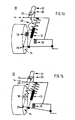
- Fig. 1a schematically a suspension system 10 of a motor vehicle not shown is shown.
- the suspension system 10 essentially comprises a spring-damper unit 12, which is arranged in a known manner between the suspension 14 and a vehicle body, not shown here for reasons of clarity.
- a pressure-additional spring 16 is present.
- the spring-damper unit 12 is associated with a second spring element 18.
- the second spring element 18 is designed as a simple additional tension spring in the form of a steel spring and is arranged substantially parallel to the spring-damper unit 12.
- the second spring element 18 is further connected to an adjustment system 20 for biasing the second spring element 18.
- the adjustment system 20 comprises a body-side fixedly mounted electric motor 22 and a threaded rod 24 and a cable connection 26 to allow a power transmission between the electric motor 22 and the second spring element 18.
- a lower linkage 28 is provided in the area around the wheel suspension 14 on the spring-damper unit 12.
- the attachment or storage of the second spring element 18 on the vehicle body is not shown.
- the second spring element 18 is slidably mount in the upper linkage to allow a corresponding bias of the second spring element 18 via the adjustment system 20.
- a tensile stress can be applied to the second spring element 18 via the adjustment system 20. Due to the tensile stress of the second spring element 18, a defined axially acting against the spring-damper unit 12 defined biasing force is generated, Fig. 1b ,
- the applied defined biasing force has two effects, namely on the one hand, a defined compression of the suspension system 10 and thus a lowering of the motor vehicle and on the other a premature engagement of existing in the compression spring pressure additional spring 16, which leads to the desired increase in the spring rate during compression.
- the conditional by the bias compression of the spring-damper unit 12 and the pressure-additional spring 16 is in Fig. 1b not shown.
- FIG. 3 is a schematic sectional view of a damper element 35.
- the second spring element 18 and the damper element form a structural unit in the present case.
- the existing in the damper element 35 Zantschfeder 36.
- the Buchanschlagfeder 36 is adjustable, ie the use of the Wernerfeder 36 is variable.
- the adjustment of the use of the Buchanschlagfeder 36 takes place for example via a below the Buchanschlagfeder 36 located driver 38, which in turn is in operative connection with the adjustment system 20.
Landscapes
- Engineering & Computer Science (AREA)
- Mechanical Engineering (AREA)
- Vehicle Body Suspensions (AREA)
- Springs (AREA)
Claims (11)
- Système de suspension variable (10) pour un véhicule automobile avec au moins un élément de ressort principal et au moins un élément d'amortissement, dans lequel l'élément de ressort principal comprend au moins un ressort porteur, dans le sens de la compression du ressort au moins un ressort supplémentaire de compression (16) et dans le sens de la détente du ressort éventuellement un ressort de butée de traction, et l'élément de ressort principal et l'élément d'amortissement sont respectivement disposés entre la suspension de roue (14) et la carrosserie du véhicule, dans lequel un deuxième élément de ressort antagoniste (18) est associé à l'élément de ressort principal entre la suspension de roue (14) et la carrosserie du véhicule et ce deuxième élément de ressort (18) peut être mis en action au choix au moyen d'un système de réglage (20), et le système de réglage (20) comprend une unité d'entraînement (22) ainsi que des moyens de liaison (24, 26) disposés entre l'unité d'entraînement (22) et le deuxième élément de ressort (18), caractérisé en ce que l'unité d'entraînement (22) est montée de façon fixe côté carrosserie et les moyens de liaison (24, 26) comprennent une broche filetée et une liaison par câble avec le deuxième élément de ressort.
- Système de suspension selon la revendication 1, caractérisé en ce que la force de ressort résultant du deuxième élément de ressort (18) est réglable au moyen du système de réglage (20).
- Système de suspension selon la revendication 1 ou 2, caractérisé en ce que les moyens de liaison (24, 26) sont réalisés sous forme réversible.
- Système de suspension selon l'une quelconque des revendications précédentes, caractérisé en ce que l'unité d'entraînement (22) est une unité électrique et/ou hydraulique et/ou pneumatique.
- Système de suspension selon l'une quelconque des revendications précédentes, caractérisé en ce que le système de réglage (20) peut être commandé et/ou régulé au moyen d'au moins un capteur en fonction de différentes grandeurs d'influence, en particulier la course de réglage, la force du ressort, la vitesse du véhicule ou analogue.
- Système de suspension selon l'une quelconque des revendications précédentes, caractérisé en ce que le système de réglage (20) ne peut être actionné qu'avec le véhicule à l'arrêt.
- Système de suspension selon l'une quelconque des revendications précédentes, caractérisé en ce que le deuxième élément de ressort (18) est disposé parallèlement à l'élément de ressort principal.
- Système de suspension selon la revendication 7, caractérisé en ce que, pour la disposition du deuxième élément de ressort (18) parallèlement à l'élément de ressort principal, il se trouve une articulation inférieure (28) sur l'élément d'amortissement ou sur la suspension de roue (14) et/ou une articulation supérieure sur la carrosserie du véhicule pour la fixation du deuxième élément de ressort (18).
- Système de suspension selon l'une quelconque des revendications 1 à 6, caractérisé en ce que le deuxième élément de ressort (18) est disposé autour de l'élément d'amortissement.
- Système de suspension selon l'une quelconque des revendications précédentes, caractérisé en ce que l'élément de ressort principal et l'élément d'amortissement forment une unité de construction - unité ressort-amortisseur - (12).
- Système de suspension selon l'une quelconque des revendications précédentes, caractérisé en ce que le deuxième élément de ressort (18) est un ressort en acier.
Applications Claiming Priority (2)
| Application Number | Priority Date | Filing Date | Title |
|---|---|---|---|
| DE102004013559 | 2004-03-19 | ||
| DE102004013559A DE102004013559B4 (de) | 2004-03-19 | 2004-03-19 | Variables Federungssystem für ein Kraftfahrzeug mit mindestens einem Hauptfederelement und mindestens einem Dämpferelement |
Publications (3)
| Publication Number | Publication Date |
|---|---|
| EP1577125A2 EP1577125A2 (fr) | 2005-09-21 |
| EP1577125A3 EP1577125A3 (fr) | 2006-12-06 |
| EP1577125B1 true EP1577125B1 (fr) | 2011-11-23 |
Family
ID=34833200
Family Applications (1)
| Application Number | Title | Priority Date | Filing Date |
|---|---|---|---|
| EP05001781A Not-in-force EP1577125B1 (fr) | 2004-03-19 | 2005-01-28 | Système de ressorts possédant une caractéristique de ressort variable pour un véhicule avec au moins un élément de ressort principal et au moins un élément d'amortissement |
Country Status (2)
| Country | Link |
|---|---|
| EP (1) | EP1577125B1 (fr) |
| DE (1) | DE102004013559B4 (fr) |
Families Citing this family (14)
| Publication number | Priority date | Publication date | Assignee | Title |
|---|---|---|---|---|
| DE102006011856A1 (de) * | 2006-03-15 | 2007-09-20 | Bayerische Motoren Werke Ag | Federungssystem für eine Fahrzeug-Radaufhängung |
| DE102007001544A1 (de) * | 2007-01-10 | 2008-07-17 | Bayerische Motoren Werke Aktiengesellschaft | Federungssystem für eine Fahrzeug-Radaufhängung mit zumindest einem zuschaltbaren Verdreh-Federelement |
| DE102006061919B4 (de) * | 2006-05-16 | 2020-03-26 | Janos Laszlo Strausz | Vorrichtung zur Abfederung eines Fahrwerkes |
| DE102007051992A1 (de) * | 2007-10-31 | 2009-05-07 | Bayerische Motoren Werke Aktiengesellschaft | Fahrwerk eines Fahrzeugs mit einer Zuganschlagfeder |
| DE102008063499A1 (de) * | 2008-12-17 | 2010-06-24 | Audi Ag | Radaufhängung für Kraftfahrzeuge |
| CN102941789B (zh) * | 2012-11-27 | 2013-08-28 | 深圳市力驰电动汽车有限公司 | 一种电动汽车的减震方法及杠杆式非独立悬挂桥装置 |
| DE102016218778A1 (de) | 2016-09-29 | 2018-03-29 | Bayerische Motoren Werke Aktiengesellschaft | Motorrad mit höhenverstellbarer Radaufhängung |
| DE102016218787A1 (de) * | 2016-09-29 | 2018-03-29 | Bayerische Motoren Werke Aktiengesellschaft | Motorrad mit fluidbetätigter Absenkvorrichtung |
| DE102016218791B4 (de) | 2016-09-29 | 2024-04-25 | Bayerische Motoren Werke Aktiengesellschaft | Motorrad mit Absenkvorrichtung für eine Radaufhängung |
| DE102016218782A1 (de) | 2016-09-29 | 2018-03-29 | Bayerische Motoren Werke Aktiengesellschaft | Motorrad mit Zugvorrichtung zur Fahrzeugabsenkung |
| DE102016218790A1 (de) | 2016-09-29 | 2018-03-29 | Bayerische Motoren Werke Aktiengesellschaft | Motorrad mit Stellvorrichtung zur wahlweisen Fahrzeugabsenkung |
| DE102017212882A1 (de) * | 2017-07-26 | 2019-01-31 | Bayerische Motoren Werke Aktiengesellschaft | Tragfeder-Dämpfer-System eines Fahrzeug-Rades |
| CN112026467B (zh) * | 2020-09-02 | 2024-02-20 | 陇南智能机械制造有限公司 | 一种车辆减震装置 |
| DE102021123385A1 (de) | 2021-09-09 | 2023-03-09 | Hasse & Wrede Gmbh | Federungsanordnung und Verfahren zum Steuern von Federungsanordnungen |
Family Cites Families (12)
| Publication number | Priority date | Publication date | Assignee | Title |
|---|---|---|---|---|
| FR1215172A (fr) * | 1958-11-07 | 1960-04-15 | Correcteur dynamique de flexibilité pour suspensions de véhicules | |
| FR1289653A (fr) * | 1961-02-25 | 1962-04-06 | Loire Atel Forges | Dispositif permettant de faire varier la charge sur des essieux |
| FR2582995A1 (fr) * | 1985-06-10 | 1986-12-12 | Nicolas Alfred | Suspension multi-ressorts |
| FR2647061B1 (fr) * | 1989-05-16 | 1991-11-29 | Bianchi Mauro | Procede de suspension a double flexibilite en opposition pour vehicule automobile et dispositif pour la mise en oeuvre |
| DE4014466A1 (de) * | 1990-05-07 | 1991-11-14 | Bosch Gmbh Robert | Fahrzeugfederung |
| US5573266A (en) * | 1995-02-13 | 1996-11-12 | Safe-T-Vans, Inc. | Vehicle body lowering system |
| DE19608617A1 (de) * | 1996-03-06 | 1997-09-11 | Linke Hofmann Busch | Verfahren zur Verbesserung des Fahrkomforts |
| US5996978A (en) * | 1996-08-27 | 1999-12-07 | Honda Giken Kogyo Kabushiki Kaisha | Hydraulic damper for vehicle |
| DE19935865B4 (de) * | 1999-07-30 | 2009-10-22 | Audi Ag | Vorrichtung zum Verändern der Federrate |
| FR2840256A1 (fr) * | 2002-05-28 | 2003-12-05 | Bianchi Mauro Sa | Organe de suspension pour vehicule et suspension ainsi equipee |
| DE10244361A1 (de) * | 2002-09-24 | 2004-04-01 | Daimlerchrysler Ag | Vorrichtung zur Schwingungsdämpfung bei einem Fahrzeug |
| JP2004268902A (ja) * | 2003-02-18 | 2004-09-30 | Nissan Motor Co Ltd | 車両の車高調整装置 |
-
2004
- 2004-03-19 DE DE102004013559A patent/DE102004013559B4/de not_active Expired - Fee Related
-
2005
- 2005-01-28 EP EP05001781A patent/EP1577125B1/fr not_active Not-in-force
Also Published As
| Publication number | Publication date |
|---|---|
| EP1577125A3 (fr) | 2006-12-06 |
| DE102004013559A1 (de) | 2005-10-13 |
| DE102004013559B4 (de) | 2006-10-19 |
| EP1577125A2 (fr) | 2005-09-21 |
Similar Documents
| Publication | Publication Date | Title |
|---|---|---|
| EP1577125B1 (fr) | Système de ressorts possédant une caractéristique de ressort variable pour un véhicule avec au moins un élément de ressort principal et au moins un élément d'amortissement | |
| DE4136262C2 (de) | Fahrwerk eines Kraftfahrzeuges | |
| DE102014201516B4 (de) | Radaufhängung mit Stabilisatoranordnung | |
| DE102010056388A1 (de) | Fahrzeug mit einem Blattfederelement zur Federung des Fahrzeugs | |
| EP1814747A2 (fr) | Procede de commande et de regulation d'un systeme de chassis actif | |
| EP1184214A2 (fr) | Actionneur pour le contrôle actif du chassis | |
| EP1569810B1 (fr) | Procede d'amortissement de vibrations | |
| DE102005015089B4 (de) | Radaufhängung für ein Fahrzeug | |
| EP3323699A1 (fr) | Procédé et dispositif de commande ou réglage de suspension de cabine d'un véhicule automobile | |
| DE2856583C2 (de) | Dreipunktanbauvorrichtung für einen Schlepper mit einem Heck- und/oder Frontanbaugerät | |
| DE102006056632A1 (de) | Achse eines zweispurigen Fahrzeugs mit Federfußpunktverschiebung und verstellbarem Querstabilisator | |
| DE10102910B4 (de) | Kraftfahrzeug, insbesondere Cabrio, mit aktiv angesteuerten Torsionsstabilisatoren | |
| WO2006131343A1 (fr) | Essieu d'un vehicule a deux voies avec deplacement du point de base du ressort | |
| DE69225225T2 (de) | Fahrzeugaufhängung | |
| DE102020211051A1 (de) | Dämpferlager zur Befestigung eines Hinterachs-Unterflurschwingungsdämpfers an einem Fahrzeugaufbau | |
| WO2020225029A1 (fr) | Ensemble stabilisateur d'un véhicule à deux voies | |
| DE102010020523A1 (de) | Federbeinsystem und Radaufhängung | |
| DE102013003958B4 (de) | Lagerungsanordnung einer Querblattfeder an einem Aufbau eines Fahrzeugs sowie Fahrzeug mit einer solchen Lagerungsanordnung | |
| DE102005043190A1 (de) | Automatisches Anziehen einer Mutter bis zum Drehmoment ohne Rutschmöglichkeit | |
| DE102009031714A1 (de) | Fahrzeug oder Fahrzeuganhänger | |
| DE3844803C2 (en) | Vehicular active suspension with controllable under or over-steer | |
| DE19651162A1 (de) | Schwingungsdämpfer für eine Überwachungseinrichtung von der Fahrsicherheit dienenden Größen | |
| EP3939828A1 (fr) | Siège de véhicule doté d'un amortissement adaptatif d'une unité oscillante affectée au siège de véhicule et procédé de réglage de l'amortissement de l'unité oscillante | |
| DE102016221306A1 (de) | Verstellbare Radaufhängung | |
| DE102019218862A1 (de) | Aktive Federung durch Änderung der Federkennlinie mit Federsperrbetätigung |
Legal Events
| Date | Code | Title | Description |
|---|---|---|---|
| PUAI | Public reference made under article 153(3) epc to a published international application that has entered the european phase |
Free format text: ORIGINAL CODE: 0009012 |
|
| AK | Designated contracting states |
Kind code of ref document: A2 Designated state(s): AT BE BG CH CY CZ DE DK EE ES FI FR GB GR HU IE IS IT LI LT LU MC NL PL PT RO SE SI SK TR |
|
| AX | Request for extension of the european patent |
Extension state: AL BA HR LV MK YU |
|
| PUAL | Search report despatched |
Free format text: ORIGINAL CODE: 0009013 |
|
| AK | Designated contracting states |
Kind code of ref document: A3 Designated state(s): AT BE BG CH CY CZ DE DK EE ES FI FR GB GR HU IE IS IT LI LT LU MC NL PL PT RO SE SI SK TR |
|
| AX | Request for extension of the european patent |
Extension state: AL BA HR LV MK YU |
|
| 17P | Request for examination filed |
Effective date: 20070606 |
|
| AKX | Designation fees paid |
Designated state(s): DE FR GB IT |
|
| 17Q | First examination report despatched |
Effective date: 20070924 |
|
| GRAP | Despatch of communication of intention to grant a patent |
Free format text: ORIGINAL CODE: EPIDOSNIGR1 |
|
| GRAA | (expected) grant |
Free format text: ORIGINAL CODE: 0009210 |
|
| GRAS | Grant fee paid |
Free format text: ORIGINAL CODE: EPIDOSNIGR3 |
|
| AK | Designated contracting states |
Kind code of ref document: B1 Designated state(s): DE FR GB IT |
|
| REG | Reference to a national code |
Ref country code: GB Ref legal event code: FG4D Free format text: NOT ENGLISH |
|
| REG | Reference to a national code |
Ref country code: DE Ref legal event code: R096 Ref document number: 502005012160 Country of ref document: DE Effective date: 20120119 |
|
| PLBE | No opposition filed within time limit |
Free format text: ORIGINAL CODE: 0009261 |
|
| STAA | Information on the status of an ep patent application or granted ep patent |
Free format text: STATUS: NO OPPOSITION FILED WITHIN TIME LIMIT |
|
| 26N | No opposition filed |
Effective date: 20120824 |
|
| REG | Reference to a national code |
Ref country code: DE Ref legal event code: R097 Ref document number: 502005012160 Country of ref document: DE Effective date: 20120824 |
|
| REG | Reference to a national code |
Ref country code: DE Ref legal event code: R084 Ref document number: 502005012160 Country of ref document: DE Effective date: 20130117 |
|
| PGFP | Annual fee paid to national office [announced via postgrant information from national office to epo] |
Ref country code: DE Payment date: 20130131 Year of fee payment: 9 |
|
| PGFP | Annual fee paid to national office [announced via postgrant information from national office to epo] |
Ref country code: IT Payment date: 20140122 Year of fee payment: 10 Ref country code: FR Payment date: 20140121 Year of fee payment: 10 |
|
| PGFP | Annual fee paid to national office [announced via postgrant information from national office to epo] |
Ref country code: GB Payment date: 20140123 Year of fee payment: 10 |
|
| REG | Reference to a national code |
Ref country code: DE Ref legal event code: R119 Ref document number: 502005012160 Country of ref document: DE |
|
| PG25 | Lapsed in a contracting state [announced via postgrant information from national office to epo] |
Ref country code: DE Free format text: LAPSE BECAUSE OF NON-PAYMENT OF DUE FEES Effective date: 20140801 |
|
| REG | Reference to a national code |
Ref country code: DE Ref legal event code: R119 Ref document number: 502005012160 Country of ref document: DE Effective date: 20140801 |
|
| GBPC | Gb: european patent ceased through non-payment of renewal fee |
Effective date: 20150128 |
|
| PG25 | Lapsed in a contracting state [announced via postgrant information from national office to epo] |
Ref country code: GB Free format text: LAPSE BECAUSE OF NON-PAYMENT OF DUE FEES Effective date: 20150128 |
|
| REG | Reference to a national code |
Ref country code: FR Ref legal event code: ST Effective date: 20150930 |
|
| PG25 | Lapsed in a contracting state [announced via postgrant information from national office to epo] |
Ref country code: FR Free format text: LAPSE BECAUSE OF NON-PAYMENT OF DUE FEES Effective date: 20150202 |
|
| PG25 | Lapsed in a contracting state [announced via postgrant information from national office to epo] |
Ref country code: IT Free format text: LAPSE BECAUSE OF NON-PAYMENT OF DUE FEES Effective date: 20150128 |