EP0483604B1 - Verfahren zum Verkürzen der Vertikalrücklaufphase eines Elektronenstrahls in einer Kathodenstrahlröhre - Google Patents
Verfahren zum Verkürzen der Vertikalrücklaufphase eines Elektronenstrahls in einer Kathodenstrahlröhre Download PDFInfo
- Publication number
- EP0483604B1 EP0483604B1 EP91117678A EP91117678A EP0483604B1 EP 0483604 B1 EP0483604 B1 EP 0483604B1 EP 91117678 A EP91117678 A EP 91117678A EP 91117678 A EP91117678 A EP 91117678A EP 0483604 B1 EP0483604 B1 EP 0483604B1
- Authority
- EP
- European Patent Office
- Prior art keywords
- vertical
- north
- correction device
- south
- electron beam
- Prior art date
- Legal status (The legal status is an assumption and is not a legal conclusion. Google has not performed a legal analysis and makes no representation as to the accuracy of the status listed.)
- Expired - Lifetime
Links
- 238000010894 electron beam technology Methods 0.000 title claims description 5
- 238000004804 winding Methods 0.000 claims description 10
- 238000000034 method Methods 0.000 claims description 7
- 230000000694 effects Effects 0.000 claims description 2
- 238000004904 shortening Methods 0.000 claims description 2
- 238000010586 diagram Methods 0.000 description 1
- 230000005669 field effect Effects 0.000 description 1
- 230000002452 interceptive effect Effects 0.000 description 1
Images
Classifications
-
- H—ELECTRICITY
- H04—ELECTRIC COMMUNICATION TECHNIQUE
- H04N—PICTORIAL COMMUNICATION, e.g. TELEVISION
- H04N3/00—Scanning details of television systems; Combination thereof with generation of supply voltages
- H04N3/10—Scanning details of television systems; Combination thereof with generation of supply voltages by means not exclusively optical-mechanical
- H04N3/16—Scanning details of television systems; Combination thereof with generation of supply voltages by means not exclusively optical-mechanical by deflecting electron beam in cathode-ray tube, e.g. scanning corrections
- H04N3/22—Circuits for controlling dimensions, shape or centering of picture on screen
- H04N3/23—Distortion correction, e.g. for pincushion distortion correction, S-correction
- H04N3/233—Distortion correction, e.g. for pincushion distortion correction, S-correction using active elements
Definitions
- the invention relates to a method for shortening the vertical return phase of an electron beam in a cathode ray tube according to the preamble of claim 1.
- a rectangle that is to be displayed on a CRT screen appears with concave sides.
- This so-called pillow distortion arises from the fact that the radius of curvature of the screen is larger than the deflection radius, which denotes the distance of the center of deflection of the electron beams from the center of the inner surface of the screen.
- a pillow distortion in the vertical direction of the screen can be eliminated by a so-called north-south correction circuit.
- horizontal frequency parabolic currents are superimposed on the originally sawtooth-shaped vertical deflection current, the amplitude of which increases approximately proportionally from the center of the image towards the upper and lower edge of the image.
- a north-south correction circuit which is coupled to a vertical output stage via a transformer.
- the main inductance of the transformer is expediently dimensioned such that it represents a low-resistance for the vertical deflection stage and a high-resistance for the north-south correction circuit during the vertical traversing phase. This ensures that the vertical deflection current, which can be thought of as composed of several sinusoidal individual currents of different frequencies, is not superimposed on the north-south correction device and has a disruptive effect on the correction current.
- the correction current from the north-south correction circuit is transmitted to the vertical output stage and - as desired - superimposed on the vertical deflection current.
- the vertical deflection current consists of higher-frequency individual currents than during the vertical traversing phase
- some of these individual currents are transmitted to the north-south correction circuit.
- the north-south correction circuit must first correct these disturbances in order to generate the required correction current. This extends the vertical retraction phase.
- the present invention has for its object to shorten the vertical return phase in a method of the type mentioned.
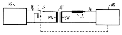
- the figure shows a block diagram of a north-south correction arrangement.
- a vertical deflection circuit AS known per se is coupled via a transformer UT to a north-south correction device NS which is also known per se.
- the vertical deflection circuit AS is connected via deflection coils LA to the secondary winding SW and the north-south correction device NS via a switch S to the primary winding PW of the transformer UT.
- the vertical deflection circuit AS At the beginning of the vertical return of an electron beam in a cathode-ray tube (not shown here), the vertical deflection circuit AS generates a control pulse from the deflection voltage applied to the deflection coil LA.
- the switch S causes the switch S to switch from a switch position I to a switch position II and to short-circuit the primary winding PW of the transformer UT and to switch the north-south correction device NS into a high-resistance state.
- the high-frequency components of the vertical deflection current Ia which the transformer UT transmits, do not interfere with the correction current Ik.
- To protect the north-south correction device NS it is switched to a high-resistance state, and the power loss of the north-south correction device is advantageously reduced. Because the north-south correction circuit NS is not connected to any disturbing high-frequency components of the vertical deflection current in this switch position, there is no need to correct these disturbance variables and the vertical return phase is shortened.
- the switch S can be implemented with a transistor, preferably a field-effect transistor.
Landscapes
- Engineering & Computer Science (AREA)
- Multimedia (AREA)
- Signal Processing (AREA)
- Details Of Television Scanning (AREA)
Description
- Die Erfindung betrifft ein Verfahren zum Verkürzen der Vertikalrücklaufphase eines Elektronenstrahls in einer Kathodenstrahlröhre gemäß dem Oberbegriff des Anspruchs 1.
- Gewöhnlich erscheint ein Rechteck, das auf einem Bildschirm einer Kathodenstrahlröhre wiedergegeben werden soll, mit konkaven Seiten. Diese sogenannte Kissenverzeichnung entsteht dadurch, daß der Krümmungsradius des Bildschirms größer ist als der Ablenkradius, der den Abstand des Ablenkmittelpunktes der Elektronenstrahlen von der Mitte der Innenfläche des Bildschirms bezeichnet. Eine Kissenverzeichnung in vertikaler Richtung des Bildschirms kann durch eine sogenannte Nord-Süd-Korrekturschaltung beseitigt werden. Mit dieser werden dem ursprünglich sägezahnförmigen Vertikalablenkstrom horizontalfrequente Parabelströme überlagert, deren Amplitude von der Bildmitte ausgehend zum oberen und unteren Bildrand hin ungefähr proportional zunimmt.
- Aus der DE-OS 35 02 622 ist eine Nord-Süd-Korrekturschaltung bekannt, die über einen Übertrager mit einer Vertikalendstufe gekoppelt ist. Bei einer derartigen Schaltungsanordnung ist die Hauptinduktivität des Übertragers zweckmäßig so bemessen, daß diese während der Vertikalhinlaufphase für die Vertikalablenkstufe einen niederohmigen Widerstand und für die Nord-Süd-Korrekturschaltung einen hochohmigen Widerstand darstellt. Dadurch wird erreicht, daß der Vertikalablenkstrom, den man sich aus mehreren sinusförmigen Einzelströmen unterschiedlicher Frequenzen zusammengesetzt denken kann, nicht auf die Nord-Süd-Korrektureinrichtung überlagert wird und störend auf den Korrekturstrom wirkt. Der Korrekturstrom von der Nord-Süd-Korrekturschaltung wird auf die Vertikalendstufe übertragen und - wie gewünscht - dem Vertikalablenkstrom überlagert.
- Dagegen wird während der im Vergleich zur Vertikalhinlaufphase kurzen Vertikalrücklaufphase, in der der Vertikalablenkstrom aus höherfrequenten Einzelströmen als während der Vertikalhinlaufphase besteht, ein Teil dieser Einzelströme auf die Nord-Süd-Korrekturschaltung übertragen. Die Nord-Süd-Korrekturschaltung muß diese Störgrößen zunächst ausregeln, um den erforderlichen Korrekturstrom zu erzeugen. Das bewirkt eine Verlängerung der Vertikalrücklaufphase.
- Aus der US-A-4 777 411 ist ein Verfahren bekannt, zur Verhinderung der Schwingneigung der Nord-Süd-Korrekturstufe bedingt durch den vertikalen Rüchlaufimpuls den Ausgangsverstärker der Stufe in der vertikalen Austastlüche in dem hochohmigen Zustand zu Schalten.
- Der vorliegenden Erfindung liegt die Aufgabe zugrunde, bei einem Verfahren der eingangs genannten Art die Vertikalrücklaufphase zu verkürzen.
- Diese Aufgabe wird durch die im kennzeichnenden Teil des Anspruchs 1 angegebenen Maßnahmen gelöst.
- Dadurch, daß während der Vertikalrücklaufphase, in der der Vertikalablenkstrom kein Korrektursignal benötigt, eine Wicklung des Übertragers, z. B. die Primärwicklung, kurzgeschlossen und die Nord-Süd-Korrektureinrichtung hochohmig geschaltet ist, wird die Vertikalrücklaufphase verkürzt. Die Nord-Süd-Korrektureinrichtung ist von der Vertikalablenkschaltung abgeschaltet und es werden keine störenden hochfrequenten Anteile des Vertikalablenkstromes der Nord-Süd-Korrektureinrichtung übertragen. Dabei wird die Verlustleistung in der Nord-Süd-Korrektureinrichtung vorteilhaft vermindert.
- Anhand der Zeichnung, in der ein Ausführungsbeispiel veranschaulicht ist, wird das neue Verfahren näher erläutert.
- Die Figur zeigt ein Blockschaltbild einer Nord-Süd-Korrekturanordnung.
- Eine an sich bekannte Vertikalablenkschaltung AS ist über einen Übertrager ÜT mit einer ebenfalls an sich bekannten Nord-Süd-Korrektureinrichtung NS gekoppelt. Dabei ist die Vertikalablenkschaltung AS über Ablenkspulen LA an der Sekundärwicklung SW und die Nord-Süd-Korrektureinrichtung NS über einen Schalter S an der Primärwicklung PW des Übertragers ÜT angeschlossen. Zu Beginn des Vertikalrücklaufs eines Elektronenstrahls in einer hier nicht dargestellten Kathodenstrahlröhre erzeugt die Vertikalablenkschaltung AS aus der an der Ablenkspule LA anliegenden Ablenkspannung einen Steuerimpuls. Dieser bewirkt, daß der Schalter S von einer Schalterstellung I in eine Schalterstellung II umschaltet und die Primärwicklung PW des Übertragers ÜT kurzgeschlossen und die Nord-Süd-Korrektureinrichtung NS in einen hochohmigen Zustand geschaltet wird. Die hochfrequenten Anteile des Vertikalablenkstromes Ia, die der Übertrager ÜT überträgt, wirken nicht störend auf den Korrekturstrom Ik. Zum Schutz der Nord-Süd-Korrektureinrichtung NS ist diese in einen hochohmigen Zustand geschaltet, und die Verlustleistung der Nord-Süd-Korrektureinrichtung ist vorteilhaft vermindert. Dadurch, daß der Nord-Süd-Korrekturschaltung NS in dieser Schalterstellung keine störenden hochfrequenten Anteile des Vertikalablenkstromes aufgeschaltet werden, entfällt eine Ausregelung dieser Störgrößen, und die Vertikalrücklaufphase wird verkürzt. Der Schalter S kann mit einem Transistor, vorzugsweise einem Feld-Effekt-Transistor, verwirklicht werden.
Claims (3)
- Verfahren zum Verkürzen der Vertikalrücklaufphase eines Elektronenstrahls in einer Kathodenstrahlröhre, wobei eine Vertikalablenkschaltung (AS) einen Vertikalhin- und -rücklauf bewirkenden Vertikalablenkstrom (Ia) erzeugt, dem ein von einer Nord-Süd-Korrektureinrichtung (NS) erzeugter Korrekturstrom (Ik) überlagert ist,
die Nord-Süd-Korrektureinrichtung (NS) an eine Primärwicklung (PW) und die Vertikalablenkschaltung (AS) an eine Sekundärwicklung (SW) eines Übertragers (ÜT) angeschlossen ist,
dadurch gekennzeichnet, daß während der Vertikalrücklaufphase eine Wicklung des Übertragers (ÜT) kurzgeschlossen und die Nord-Süd-Korrektureinrichtung (NS) hochohmig geschaltet wird. - Verfahren nach Anspruch 1, dadurch gekennzeichnet, daß die Primärwicklung (PW) kurzgeschlossen wird.
- Verfahren nach Anspruch 1 oder 2, dadurch gekennzeichnet, daß die Vertikalablenkschaltung (AS) zu Beginn der Vertikalrücklaufphase einen Steuerimpuls erzeugt, der bewirkt, daß die Primärwicklung (PW) kurzgeschlossen und die Nord-Süd-Korrektureinrichtung (NS) hochohmig geschaltet wird.
Applications Claiming Priority (2)
| Application Number | Priority Date | Filing Date | Title |
|---|---|---|---|
| DE4034530A DE4034530A1 (de) | 1990-10-30 | 1990-10-30 | Verfahren zum verkuerzen der vertikalruecklaufphase eines elektronenstrahls in einer kathodenstrahlroehre |
| DE4034530 | 1990-10-30 |
Publications (3)
| Publication Number | Publication Date |
|---|---|
| EP0483604A2 EP0483604A2 (de) | 1992-05-06 |
| EP0483604A3 EP0483604A3 (en) | 1992-07-08 |
| EP0483604B1 true EP0483604B1 (de) | 1995-05-24 |
Family
ID=6417331
Family Applications (1)
| Application Number | Title | Priority Date | Filing Date |
|---|---|---|---|
| EP91117678A Expired - Lifetime EP0483604B1 (de) | 1990-10-30 | 1991-10-16 | Verfahren zum Verkürzen der Vertikalrücklaufphase eines Elektronenstrahls in einer Kathodenstrahlröhre |
Country Status (2)
| Country | Link |
|---|---|
| EP (1) | EP0483604B1 (de) |
| DE (2) | DE4034530A1 (de) |
Family Cites Families (2)
| Publication number | Priority date | Publication date | Assignee | Title |
|---|---|---|---|---|
| SE8405770L (sv) * | 1983-11-25 | 1985-05-26 | Rca Corp | Krets for korrigering av distorsion i televisionsraster |
| US4777411A (en) * | 1987-01-22 | 1988-10-11 | Zenith Electronics Corporation | Top/bottom active pincushion circuit with ringing inhibit |
-
1990
- 1990-10-30 DE DE4034530A patent/DE4034530A1/de not_active Withdrawn
-
1991
- 1991-10-16 EP EP91117678A patent/EP0483604B1/de not_active Expired - Lifetime
- 1991-10-16 DE DE59105575T patent/DE59105575D1/de not_active Expired - Fee Related
Also Published As
| Publication number | Publication date |
|---|---|
| DE4034530A1 (de) | 1992-05-07 |
| EP0483604A3 (en) | 1992-07-08 |
| EP0483604A2 (de) | 1992-05-06 |
| DE59105575D1 (de) | 1995-06-29 |
Similar Documents
| Publication | Publication Date | Title |
|---|---|---|
| DD244457A5 (de) | Schaltungsanordnung zur korrektur einer rasterverzeichnung fuer ein video-wiedergabegeraet mit einer rechteckigen, planaren bildroehre | |
| DD244873A5 (de) | Korrekturschaltung fuer rasterverzerrungen | |
| DE69626606T2 (de) | Vorrichtung zur Korrektur von Kissenverzerrungen | |
| DE4113922B4 (de) | Schaltungsanordnung zur Stabilisierung der Hochspannung für ein Video-Bildwiedergabegerät | |
| DE69724574T2 (de) | Kathodenstrahlröhre | |
| DE3608597A1 (de) | Schaltung zur erzeugung ablenkfrequenter parabolischer schwingungen | |
| EP0483604B1 (de) | Verfahren zum Verkürzen der Vertikalrücklaufphase eines Elektronenstrahls in einer Kathodenstrahlröhre | |
| DE3514259C2 (de) | ||
| DE3715688C2 (de) | Vertikalablenkschaltung für ein Videowiedergabegerät | |
| DE1915526A1 (de) | Hochspannungsregelkreis fuer Farbfernsehempfaenger | |
| DE69729973T2 (de) | Vertikalablenkschaltung mit Rasterkorrektur | |
| DE69720079T2 (de) | Mit horizontaler zentrierung kombinierte horizontale parallelogramm-korrektur | |
| EP0339311B1 (de) | Schaltungsanordnung zur Korrektur von Geometrieverzerrungen auf dem Bildschirm einer Kathodenstrahlröhre | |
| DE2832665C2 (de) | Rasterkorrekturschaltung | |
| DE1437846B2 (de) | Schaltungsanordnung zur Entzerrung des durch den Elektronenstrahl einer Fernsehbildröhre auf dem Leuchtschirm geschriebenen Rasters | |
| DE1912038C3 (de) | Horizontalkonvergenzschaltung | |
| DE1925872A1 (de) | Konvergenzschaltung | |
| DE3331567C2 (de) | Schaltung für die Ost-West-Kissenkorrektur in einem Farbfernsehempfänger | |
| DE60130837T2 (de) | Farbfernsehgerät und Farbbildröhrengerät | |
| DE2559863B2 (de) | Ost-West-Kissenkorrekturschaltung | |
| DE60028535T2 (de) | Ablenkschaltungen, die über einen filter gekoppelt sind | |
| EP0129761B1 (de) | Schaltungsanordnung für die Vertikalablenkschaltung von Elektronenstrahlen in einer Fernsehbildröhre | |
| DE2806197A1 (de) | Abgleichschaltung fuer farbfernsehempfaenger | |
| DE2556933A1 (de) | Ablenkschaltung | |
| DE2605251C2 (de) |
Legal Events
| Date | Code | Title | Description |
|---|---|---|---|
| PUAI | Public reference made under article 153(3) epc to a published international application that has entered the european phase |
Free format text: ORIGINAL CODE: 0009012 |
|
| AK | Designated contracting states |
Kind code of ref document: A2 Designated state(s): DE FR GB NL SE |
|
| PUAL | Search report despatched |
Free format text: ORIGINAL CODE: 0009013 |
|
| AK | Designated contracting states |
Kind code of ref document: A3 Designated state(s): DE FR GB NL SE |
|
| 17P | Request for examination filed |
Effective date: 19920724 |
|
| 17Q | First examination report despatched |
Effective date: 19940902 |
|
| GRAA | (expected) grant |
Free format text: ORIGINAL CODE: 0009210 |
|
| AK | Designated contracting states |
Kind code of ref document: B1 Designated state(s): DE FR GB NL SE |
|
| REF | Corresponds to: |
Ref document number: 59105575 Country of ref document: DE Date of ref document: 19950629 |
|
| ET | Fr: translation filed | ||
| GBT | Gb: translation of ep patent filed (gb section 77(6)(a)/1977) |
Effective date: 19950712 |
|
| PLBE | No opposition filed within time limit |
Free format text: ORIGINAL CODE: 0009261 |
|
| STAA | Information on the status of an ep patent application or granted ep patent |
Free format text: STATUS: NO OPPOSITION FILED WITHIN TIME LIMIT |
|
| 26N | No opposition filed | ||
| PGFP | Annual fee paid to national office [announced via postgrant information from national office to epo] |
Ref country code: GB Payment date: 19960919 Year of fee payment: 6 |
|
| PGFP | Annual fee paid to national office [announced via postgrant information from national office to epo] |
Ref country code: SE Payment date: 19961022 Year of fee payment: 6 |
|
| PGFP | Annual fee paid to national office [announced via postgrant information from national office to epo] |
Ref country code: NL Payment date: 19961024 Year of fee payment: 6 |
|
| PGFP | Annual fee paid to national office [announced via postgrant information from national office to epo] |
Ref country code: FR Payment date: 19961025 Year of fee payment: 6 |
|
| PG25 | Lapsed in a contracting state [announced via postgrant information from national office to epo] |
Ref country code: GB Free format text: LAPSE BECAUSE OF NON-PAYMENT OF DUE FEES Effective date: 19971016 |
|
| PG25 | Lapsed in a contracting state [announced via postgrant information from national office to epo] |
Ref country code: SE Free format text: LAPSE BECAUSE OF NON-PAYMENT OF DUE FEES Effective date: 19971017 |
|
| PG25 | Lapsed in a contracting state [announced via postgrant information from national office to epo] |
Ref country code: FR Free format text: THE PATENT HAS BEEN ANNULLED BY A DECISION OF A NATIONAL AUTHORITY Effective date: 19971031 |
|
| PG25 | Lapsed in a contracting state [announced via postgrant information from national office to epo] |
Ref country code: NL Free format text: LAPSE BECAUSE OF NON-PAYMENT OF DUE FEES Effective date: 19980501 |
|
| GBPC | Gb: european patent ceased through non-payment of renewal fee |
Effective date: 19971016 |
|
| NLV4 | Nl: lapsed or anulled due to non-payment of the annual fee |
Effective date: 19980501 |
|
| EUG | Se: european patent has lapsed |
Ref document number: 91117678.2 |
|
| REG | Reference to a national code |
Ref country code: FR Ref legal event code: ST |
|
| PGFP | Annual fee paid to national office [announced via postgrant information from national office to epo] |
Ref country code: DE Payment date: 20001218 Year of fee payment: 10 |
|
| PG25 | Lapsed in a contracting state [announced via postgrant information from national office to epo] |
Ref country code: DE Free format text: LAPSE BECAUSE OF NON-PAYMENT OF DUE FEES Effective date: 20020702 |