EP0483071A2 - Appareil de découpe par fil, par électro-érosion - Google Patents
Appareil de découpe par fil, par électro-érosion Download PDFInfo
- Publication number
- EP0483071A2 EP0483071A2 EP19910810824 EP91810824A EP0483071A2 EP 0483071 A2 EP0483071 A2 EP 0483071A2 EP 19910810824 EP19910810824 EP 19910810824 EP 91810824 A EP91810824 A EP 91810824A EP 0483071 A2 EP0483071 A2 EP 0483071A2
- Authority
- EP
- European Patent Office
- Prior art keywords
- arm unit
- wire
- plate member
- tank
- fluid
- Prior art date
- Legal status (The legal status is an assumption and is not a legal conclusion. Google has not performed a legal analysis and makes no representation as to the accuracy of the status listed.)
- Granted
Links
Images


Classifications
-
- B—PERFORMING OPERATIONS; TRANSPORTING
- B23—MACHINE TOOLS; METAL-WORKING NOT OTHERWISE PROVIDED FOR
- B23H—WORKING OF METAL BY THE ACTION OF A HIGH CONCENTRATION OF ELECTRIC CURRENT ON A WORKPIECE USING AN ELECTRODE WHICH TAKES THE PLACE OF A TOOL; SUCH WORKING COMBINED WITH OTHER FORMS OF WORKING OF METAL
- B23H7/00—Processes or apparatus applicable to both electrical discharge machining and electrochemical machining
- B23H7/02—Wire-cutting
Definitions
- the present invention relates generally to a wire-cut electroerosion apparatus. More specifically, the present invention relates to a wire-cut electrical discharge machining ("EDM”) apparatus for performing submerged machining.
- EDM electrical discharge machining
- wire-cut EDM electrical discharge machining may be performed with the workpiece submerged in a processing tank that is filled with a machining fluid.
- a wire electrode runs between an upper guide head and a lower guide head with the two guide heads mounted on an upper arm unit and a lower arm unit, respectively.
- an opening is made in the processing tank for inserting the lower arm unit with the lower guide head into the tank.
- Positioning of the workpiece relative to the wire electrode is accomplished by moving the processing tank in two orthogonal directions in a plane parallel to its base. One direction is parallel to the axis of the lower arm unit and the other direction is parallel to the tank wall having the opening.
- Sealing members are then placed between the sealing plate 4 and the wall of the processing tank 2 and also between the wall and the lower arm unit 1.
- the positioning of sealing members between the sealing plate 4 and the lower arm unit 1 creates a problem in terms of frictional resistance, also called the sealing resistance.
- the sealing resistance may cause the lower arm unit to deform thereby degrading machining accuracy.
- An object of the present invention is to provide an electroerosion apparatus which reduces the sealing resistance to the arm unit and also improves the machining accuracy.
- Another object of the invention is to provide a tank sealing system for an electroerosion apparatus which seals the arm unit when power is not supplied to the sealing system.
- a further object of the present invention is to seal the arm unit without introducing unwanted bubbles into the machining area of the processing tank.
- Another object of the present invention is to seal the arm unit without agitating the machining fluid at the machining location.
- Another object of the present invention is to provide an electroerosion apparatus in which fluid is allowed to escape in a controlled flow.
- a further object of the present invention is to provide an effective means for collecting machining fluid escaping from the tank and returning it to the processing tank.
- Another object of the present invention is to provide an electroerosion apparatus in which a space between the arm unit and an adjacent member is maintained precisely.
- Another object of the present invention is to provide an electroerosion apparatus in which the sliding resistance of the axial seal for the arm unit is minimized.
- the present invention generally relates to a wire-cut electrical discharge machining apparatus ("EDM") in which an opening is formed in the wall of the processing tank for passage of a lower arm unit.
- the processing tank is filled with a machining fluid for performing submerged machining operations on the workpiece.
- injection nozzles associated with a sliding plate are provided to hydraulically "seal" the space between the arm unit and the opening in the processing tank wall. These injection nozzles inject a compressed fluid from the periphery of an opening in the slide plate towards the arm unit and the processing tank. In this arrangement, this energized flow of compressed fluid prevents fluid in the processing tank from escaping through the space between the slide plate opening and the arm unit. This arrangement reduces the sealing resistance against the arm unit, since no sealing members physically contact the arm unit. This, in turn, improves machining accuracy.
- a shield plate is placed near the outlet of the injection nozzles to prevent the compressed fluid from flowing directly into the middle of the processing tank.
- the shield plate prevents the machining fluid from becoming agitated which further improves the machining accuracy.
- Additional structure may be advantageously provided to remove bubbles caused by the injection of compressed fluid and direct the bubbles toward the surface of the fluid and away from the machining area of the tank.
- the wire-cut electrical discharge machining apparatus may also comprise a processing tank having an opening for the passage of a lower arm unit.
- a covering member placed around the arm unit, covers the opening by sliding side-to-side with the arm unit. Machining fluid flows in the space between the covering member and the arm unit.
- a sub-tank may be provided for catching and recirculating the fluid flowing between the arm unit and the covering member.
- the covering member may have a recessed portion connected to an aspirator for drawing in machining fluid. The sealing resistance between the slide plate and arm unit is reduced and machining fluid flow controlled.
- a wire-cut EDM apparatus comprising a processing tank having an opening for passage of a lower arm unit.
- a covering member is positioned around the arm unit and covers the opening by sliding side-to-side with the arm unit.
- a contact member may be connected to the covering member for contacting the arm unit.
- the contact member has a low coefficient of friction and supplies a low frictional axial seal with respect to the arm unit.
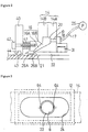
- Figure 1 illustrates a cross-sectional view of one embodiment of the wire-cut EDM apparatus.
- a workpiece 2 is submerged into a processing tank 3 filled with a machining fluid 15.
- a wire electrode 1 is guided from an upper guide unit 8 (schematically shown), to a lower guide unit 9 (schematically shown), to a pulley 11, and then through the inside of a pipe 6.
- the processing tank 3 is supported by a table 4A and a saddle 4B that sits on a bed 7.
- the table 4A moves along an X-axis, which is in a direction parallel to the wall of the processing tank 3 having an opening 24, and the saddle 4B moves along a Y-axis, which is in a direction parallel to the axis of the pipe 6. This enables two-dimensional positioning of the processing tank 3 with respect to the workpiece 2.
- the machining fluid 15 may be drained through the drain outlet 23 by the release of a drain valve 27.
- Each of the guide units 8 and 9 has an associated fluid flushing nozzle 10 (illustrated schematically).
- the upper guide unit 8 is supported by an upper arm (not illustrated) and the lower guide unit is supported by a lower arm unit 5.
- the lower arm unit 5 is positioned inside the cylindrical pipe 6 and both pass into the processing tank through the opening 24 in the wall of the tank 3.
- the term “arm unit” will be used to refer to both the lower arm unit 5 and the pipe 6.
- a slide plate 14 is positioned between the opening 24 of the processing tank 3 and the arm unit.
- Slide plate 14 may advantageously be generally rectangular in shape, having an opening at or about its center for passage of the arm unit.
- the slide plate 14 covers the opening 24 and serves as a sealing means.
- An outside edge of the slide plate 14 is attached to a plate holding guide 12 by a seal member 13.
- the plate holding guide 12 is connected to the inside wall of the processing tank 3.
- a plurality of injection nozzles 16 are located on the inside surface of the slide plate 14 facing the pipe 6.
- the injection nozzles 16 are best appreciated in the enlarged view of Figure 2.
- the slide plate 14 preferably comprises a pair of plates 14A and 14B positioned adjacent each other.
- the injection nozzle 16 and a compressor chamber 20 are formed in a space between the plates 14A and 14B, and a supply conduit 19 is formed in the plate 14B.
- the outlet of the nozzle 16 is disposed on the face of slide plate 14 near the periphery of the space between the arm unit and the face of the slide plate 14 which opposes the arm unit.
- the injection nozzles 16 may be supplied with fluid under pressure by a pump 25 (indicated schematically) through supply pipe 17, pipe coupling 18, supply conduit 19, and compressor chamber 20.
- the pressurized fluid is preferably supplied from the pump 25 under the control of a valve, not shown, but which, as will be understood by the artisan, may be magnetically or electrically activated.
- the machining fluid may be used as the source for this pressurized fluid.
- the injection nozzles have a tip 16A which is narrower than the base 16B and is directed towards the inside of the processing tank 3 so that fluid may be forced into the processing tank 3.
- the pressurized fluid creates a fluid flow, indicated by the arrow 26B, along the surface of the pipe 6 towards the inside 21 of the processing tank 3. This flow acts as a hydraulic curtain to prevent fluid in the tank 3 from escaping.
- the fluid flows in the space between the pipe 6 and the edge of the slide plate 14.
- a second fluid flow, indicated by the arrow 26A, is created along the inside of slide plate 14.
- the fluid flow 26A approaches the pipe 6, it merges with the fluid flow 26B.
- the confluence of the two flows 26A and 26B prevent fluid from leaking out of the space between the pipe 6 and the slide plate 14.
- a shield plate 40 is advantageously positioned downstream of the outlet of the nozzles 16.
- the shield plate 40 prevents the fluid in the tank 3 from becoming agitated and also prevents bubbles from being introduced into the tank.
- the shield plate 40 may be attached to the inside rim of the slide plate 14b by a bolt 42 and a washer 41.
- the washer 41 spaces the shield plate 40 from the slide plate 14.
- the shield plate 40 is placed near the outlet of the injection nozzle 16 and parallel to the slide plate 14.
- the length of the washer 41 is preferably on the order of at least 3 mm.
- a relief groove 44 is preferably machined into the inside edge of the shield plate 40 for enhancing the buffering function of the injected fluid.
- the space 43 between the shield plate 40 and the pipe 6 is narrower than the spaces 21 and 22, preferably the space 43 is on the order of from about 0.2 mm to 1.0 mm.
- the spaces 21 and 22 should preferably be maintained as precisely as possible for the proper control of the fluid flow. Since the arm unit does not move up or down, the pipe 6 and the slide plate 14 can be kept in their initial position. The arm unit, however, does move to the right and left. Therefore, the slide plate 14 must also move in order to maintain this spacing. Therefore, as shown in Figure 3, a positioning plate 64 is provided on both sides of the arm unit to maintain the spaces. As best seen in Figure 4, the positioning plate 64 may be fastened to the slide plate 14 by screws with the tip of the plate 64 touching the pipe 6. The positioning plate 64 causes the slide plate 14 to move with the pipe 6 while maintaining the size of the spaces 21 and 22.
- Machining fluid 15 could be drained through the drain outlet 23 whenever a working operation is finished. However, this is not a very efficient mode of operation. Therefore, the use of additional sealing structure is desirable.
- this additional sealing means may comprise a clamp band 31 having a sealing ring 30 attached to its inside perimeter.
- Figure 5 depicts the clamp band 31 in its open, non-sealing position
- Figure 7 depicts the clamp band 31 in its closed, sealing position.
- the sealing ring 30 is firmly attached to the pipe 6, thereby sealing the space between the pipe 6 and the clamp band 31.
- the clamp band 31 is connected to the outer wall of the slide plate 14.
- a cylinder 32 is attached to the slide plate 14 and houses a piston 33, part of a piston rod 34, and a spring 35.
- the operation of the sealing means is as follows.
- a pump 36 pushes the piston 33 to its open position as shown in Figure 5.
- the spring 35 forces the piston back to its closed, sealing position as shown in Figure 7.
- the clamp band 31 tightens around the pipe 6 and seals the space without consuming any energy.
- compressed air may be used in place of the spring 35 for the clamping purpose.
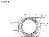
- FIG. 8 A further embodiment of this sealing means is shown in Figure 8.
- the space around the pipe 6 is sealed with two clamp halves 56 and 57.
- the clamp halves 56 and 57 are in the shape of two symmetrical semi-circular arcs.
- a pair of cylinders 58 and 59 respectively press the clamp halves 56 and 57 against the pipe 6 and the holding plate 60, thereby sealing the space between the side plate 14 and pipe 6.
- an efficient and uniform sealing condition is obtained by the use of two symmetrical clamp halves.
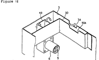
- FIG. 9 Another embodiment of the present invention is shown in Figures 9 and 10.
- the slide plate 14 is positioned to the outside of the processing tank 3.
- the unit 16a of the injection nozzle 16 is formed independently of the slide plate 14 and is fastened onto the slide plate 14.
- a prism unit 49 may be provided in the processing tank 3.
- the prism unit 49 provides a fluid "room" which surrounds the shield plates 40A and 40B.
- the prism unit 49 preferably has a square-shaped cross section with an opened upper end and a lower end closed by a bottom plate.
- the arm unit penetrates the tank wall through an opening in the lower portion of the prism unit 49.
- the prism unit 49 has shield plates 40A and 40B positioned inside it. Shield plates 40A and 40B are preferably fastened to the prism unit 49 by means of bolt 42, washers 41A and 41B, and nut 62.
- a partition plate 50 is fastened to the walls of the processing tank 3.
- the partition plate 50 preferably extends below the surface of the machining fluid and partitions only an upper layer of the fluid.
- similar structure can be used with the embodiment of Figures 1 and 2.
- the prism unit 49 and partition plate 50 create a fluid room which leads any bubbles generated by the injected tank sealing fluid upward toward the surface of the machining fluid.
- the partition plate 50 prevents bubbles from disbursing throughout the tank 3.
- the shield plates 40A and 40B provide efficient shielding between the fluid injected from the injection nozzles 16 and the wire electrode.
- Weirs 3A and 50A ( Figure 11) are provided in the wall of the processing tank 3 and in the partition plate 50 to maintain the machining fluid surface at a desired level.
- a suction device may also be included in the processing tank 3.
- suction pipe 55 may be inserted into the machining fluid from above the processing tank 3 and prism unit 49.
- This suction pipe 55 is connected to a suction device to draw off gas from the dissipating bubbles at the surface of the fluid in the prism unit 49.
- the suction pipe 55 and suction device preferably includes a filtering unit (not shown) for separating the bubbles from the machining fluid, the latter being returned to the processing tank 3 or fluid reservoir.
- the suction device and suction pipe 55 are not essential as most bubbles will be sufficiently eliminated by the prism unit 49.
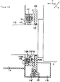
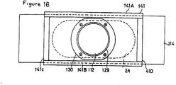
- a third embodiment of the invention shown in Figures 12 and 13, includes a processing tank 3 having an opening 24 in one of its walls.
- a non-loading, axial sliding seal is used.
- the opening 24 is closed by a covering member 114.
- the covering member 114 comprises a plate-like member having a through hole for passage of a lower arm unit 112.
- the lower arm unit 112 is supported by the column C and extends into the processing tank 3.
- the covering member 114 fits inside a guide frame 141, which is secured to the wall of the processing tank 3, for example by screws.
- An annular member 116A is secured to one end of the covering member 114.
- the member 116A creates an annular space 118 with respect to the arm unit 112.
- the space 118 is on the order of about 0.05 to 0.1 mm.
- a sub-tank 119 is positioned beneath the processing tank 3 and covering member 114.
- the sub-tank 119 collects machining fluid passing through the annular space 118. While its capacity will vary depending on the size of the tank 3 and other factors, for a typical wire-cut EDM installation the capacity of the sub-tank 119 is preferably on the order of about 3 liters.
- a shield plate 120 is positioned behind the covering member 114 and moves along the X axis with the arm unit 112.
- the shield plate 120 moves along a guide member 121, which is fastened to a guide rail 119′ positioned at the bottom of the sub-tank 119.
- the shield plate 120 has an opening through which the arm unit 112 passes.
- a seal 122 is used to prevent the machining fluid from flowing to the column side of the shield plate 120.
- the seal 122 preferably only applies a very slight contact pressure against the arm unit 112 to avoid applying a load to the arm unit 112 during motion of the processing tank 3.
- the guide frame 141 is preferably rectangularly shaped and includes sides 141A, 141B, 141C, and 141D which surround the opening 24 in the processing tank 3.
- the annular member 116A discussed above, is concentrically disposed with respect to the lower arm unit 112, thereby forming the annular space 118.
- FIG 14 illustrates a fourth embodiment of the invention and represents a variation on the embodiment of Figures 12 and 13.
- an annular member 116B is secured to the covering member 114.
- the annular member 116B is configured to form a space 118A between it and the arm unit 112.
- An elbow unit 124 positioned at a drain opening at the lower end of the annular member 116B at a recessed portion 123 thereof feeds into pipe 125.
- the elbow unit 124 and pipe 125 form part of an aspirator unit. Machining fluid flowing through the space 118 into the space 118A is aspirated through the elbow unit 124 and pipe 125.
- a sub-tank 119 may also be provided in case the flow through the spaces 118 and 118A is greater than the intake capacity of the aspirator. Machining fluid aspirated through the pipe 112 or drained from the sub-tank 119 may then be returned to the processing tank 3 or other fluid reservoir. Since the machining fluid is allowed to freely flow through the spaces 118 and 118A, axial sliding resistance on the arm 112 is reduced and the machining accuracy improved.
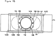
- Figures 15 and 16 illustrate a fifth embodiment of the invention which represents a variation of the embodiment of Figures 12 and 13.
- the covering member 114 includes a recessed portion 126 in which an elastic tube 27 is positioned.
- a slide sheet 129 is fastened to the covering member 114, preferably by a holding plate 130.
- the slide sheet 129 should have a low coefficient of friction and may, for example, comprise a layer of polytetraflouroethylene on the order of 0.5 mm in thickness.
- the pressure inside the elastic tube 127 may be controlled by use of a pipe 128 to ensure minimal sliding resistance between the arm 112 and slide sheet 129 consistent with adequate sealing.
- a supply of compressed air or pressurized fluid may be supplied to the elastic tube 127.
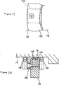
- Figures 17 through 20 illustrate a sixth embodiment of the invention which represents yet another variation of the embodiment of Figures 12 and 13.
- a packing 131 preferably formed of a low coefficient of friction material such as polytetraflouroethylene-soaked fibers in the form of a piece of cloth or felt, is contained in a recess in a cap 135.
- the cap 135 is preferably positioned in a notch provided in the covering member 114.
- the cap 135 is also preferably of a low friction material such as polytetraflouroethylene.
- An elastic member 136 positioned between the covering member 114 and the cap 135, preferably around the entire perimeter of the cap, to bias the cap 135 and packing 131 against the arm unit 112.
- the member 136 should be selected to exert minimal bias to seal while minimizing sliding resistance on the arm unit.
- a mudguard packing or dam 132 is positioned on the arm unit 112 between the processing tank 3 and the packing 131.
- the mud guard packing 132 inhibits any particles deposited on the arm unit 112 from reaching the packing 131.
- Another dam, in the form of drain packing 133 may be advantageously positioned on the arm unit 112 behind the packing 131 to prevent any machining fluid passing the packing 131 from contacting the column C.
- a plurality of binding members 150 may be secured to the covering member 114 for supporting the first dam, i.e., mudgard packing 132 and the second dam, i.e., drain packing 133.
- Positioning plates 134 may also be secured to the covering member 114. As best seen in Figure 19, the positioning plates 134 maintain the spacing between the covering member 114 and the arm unit 112. The positioning plates 134 may also be used in the third through fifth embodiments described above.
- This embodiment allows the arm unit 112 to move from side to side and also axially while maintaining a axial seal which has a low coefficient of friction.
- a shield plate may be provided in the rear of the slide plate 14 so that any fluid that leaves the opening 24 may be led to a supplemental tank as quickly as possible.
- Various modifications may also be made to the power cut off sealing embodiments.
- the invention is not intended to be limited to the described structures for collecting and recirculating fluid from the work tank as other devices may also advantageously be used.
Landscapes
- Chemical & Material Sciences (AREA)
- Chemical Kinetics & Catalysis (AREA)
- Electrochemistry (AREA)
- Engineering & Computer Science (AREA)
- Mechanical Engineering (AREA)
- Electrical Discharge Machining, Electrochemical Machining, And Combined Machining (AREA)
Priority Applications (1)
| Application Number | Priority Date | Filing Date | Title |
|---|---|---|---|
| EP94107816A EP0610974B1 (fr) | 1990-10-26 | 1991-10-25 | Appareil de découpe par fil, par électro-érosion |
Applications Claiming Priority (6)
| Application Number | Priority Date | Filing Date | Title |
|---|---|---|---|
| JP29032690A JPH04164516A (ja) | 1990-10-26 | 1990-10-26 | 放電加工装置 |
| JP290326/90 | 1990-10-26 | ||
| JP57814/91 | 1991-02-28 | ||
| JP03057814A JP3107408B2 (ja) | 1991-02-28 | 1991-02-28 | ワイヤカット放電加工装置 |
| JP10396491A JPH04310317A (ja) | 1991-04-09 | 1991-04-09 | 放電加工装置 |
| JP103964/91 | 1991-04-09 |
Related Child Applications (2)
| Application Number | Title | Priority Date | Filing Date |
|---|---|---|---|
| EP94107816A Division EP0610974B1 (fr) | 1990-10-26 | 1991-10-25 | Appareil de découpe par fil, par électro-érosion |
| EP94107816.4 Division-Into | 1991-10-25 |
Publications (3)
| Publication Number | Publication Date |
|---|---|
| EP0483071A2 true EP0483071A2 (fr) | 1992-04-29 |
| EP0483071A3 EP0483071A3 (en) | 1992-10-28 |
| EP0483071B1 EP0483071B1 (fr) | 1995-03-01 |
Family
ID=27296389
Family Applications (2)
| Application Number | Title | Priority Date | Filing Date |
|---|---|---|---|
| EP94107816A Expired - Lifetime EP0610974B1 (fr) | 1990-10-26 | 1991-10-25 | Appareil de découpe par fil, par électro-érosion |
| EP91810824A Expired - Lifetime EP0483071B1 (fr) | 1990-10-26 | 1991-10-25 | Appareil de découpe par fil, par électro-érosion |
Family Applications Before (1)
| Application Number | Title | Priority Date | Filing Date |
|---|---|---|---|
| EP94107816A Expired - Lifetime EP0610974B1 (fr) | 1990-10-26 | 1991-10-25 | Appareil de découpe par fil, par électro-érosion |
Country Status (4)
| Country | Link |
|---|---|
| US (1) | US5171955A (fr) |
| EP (2) | EP0610974B1 (fr) |
| DE (2) | DE69107778T2 (fr) |
| HK (1) | HK109295A (fr) |
Cited By (2)
| Publication number | Priority date | Publication date | Assignee | Title |
|---|---|---|---|---|
| EP0936017A3 (fr) * | 1998-02-11 | 2004-01-14 | Ona Electro-Erosion, S.A. | Dispositif d'échantéité pour le bras inférieur d'une machine à usiner par électroérosion |
| CN106142368A (zh) * | 2015-03-24 | 2016-11-23 | 苏州文迪光电科技有限公司 | 滤光片切割装置 |
Families Citing this family (12)
| Publication number | Priority date | Publication date | Assignee | Title |
|---|---|---|---|---|
| JP2691487B2 (ja) * | 1992-01-18 | 1997-12-17 | ファナック株式会社 | ワイヤカット放電加工装置 |
| EP0781619A1 (fr) | 1995-12-15 | 1997-07-02 | Cree Research, Inc. | Procédé de fabrication des plaquettes en carbure de silicium à partir des monocristaux en carbure de silicium |
| ES1034074Y (es) * | 1996-05-06 | 1997-05-01 | Ona Electro Erosion | Dispositivo de semi-estanqueidad entre elementos moviles en maquinas de electroerosion. |
| US6073935A (en) * | 1998-03-17 | 2000-06-13 | Ona Electro-Erosion, S.A. | Leaktight seal device for lower arm of a spark erosion machine or electrical discharge machining (EDM) device |
| JP4004666B2 (ja) * | 1998-10-12 | 2007-11-07 | 株式会社ソディック | ワイヤカット放電加工機 |
| JP3827894B2 (ja) * | 1999-10-12 | 2006-09-27 | 株式会社ソディック | ワイヤカット放電加工機のシール装置 |
| TW479587U (en) * | 2000-01-13 | 2002-03-11 | Castek Mechatron Industry Co L | Leakage proof device for the working tank of a wire cutting machine |
| JP3815328B2 (ja) * | 2000-02-25 | 2006-08-30 | 三菱電機株式会社 | ワイヤ放電加工装置 |
| US6278074B1 (en) * | 2000-02-28 | 2001-08-21 | Lincoln Global, Inc. | Method and system for welding railroad rails |
| JP2001277049A (ja) * | 2000-03-30 | 2001-10-09 | Brother Ind Ltd | ワイヤ放電加工機 |
| JP4109269B2 (ja) * | 2005-04-25 | 2008-07-02 | ファナック株式会社 | ワイヤカット放電加工機におけるシール構造 |
| JP2007276026A (ja) * | 2006-04-04 | 2007-10-25 | Fanuc Ltd | ワイヤカット放電加工機 |
Family Cites Families (12)
| Publication number | Priority date | Publication date | Assignee | Title |
|---|---|---|---|---|
| DE2145830A1 (de) * | 1971-09-14 | 1973-03-15 | Johann Rij | Pneumatische dichtung fuer rotierende bzw. hin- und hergehende wellen |
| FR2209431A5 (en) * | 1972-12-01 | 1974-06-28 | Alsthom Cgee | Movable sealing joint with teflon - pressed elastically against seat by inflated elastic chamber |
| GB1507948A (en) * | 1975-12-02 | 1978-04-19 | English Electric Co Ltd | Pipe joints |
| US4421323A (en) * | 1982-08-30 | 1983-12-20 | Greene, Tweed & Co., Inc. | Oil well string member with static seal |
| CH654777A5 (fr) * | 1983-07-27 | 1986-03-14 | Charmilles Sa Ateliers | Machine pour decouper par electro-erosion. |
| DE3337033C2 (de) * | 1983-10-12 | 1987-04-30 | Fa. Carl Freudenberg, 6940 Weinheim | Achs- oder Wellendichtung |
| US4589689A (en) * | 1984-04-16 | 1986-05-20 | Hughes Tool Company | Energized seal for upper termination |
| DE3642082A1 (de) * | 1985-12-21 | 1987-06-25 | Zahnradfabrik Friedrichshafen | Fluessigkeitsdichtung fuer zueinander rotations- und axialbewegliche maschinenteile |
| CH673248A5 (fr) * | 1987-08-28 | 1990-02-28 | Charmilles Technologies | |
| JPH0739056B2 (ja) * | 1988-10-17 | 1995-05-01 | 三菱電機株式会社 | ワイヤ放電加工装置 |
| JPH0724169Y2 (ja) * | 1989-01-27 | 1995-06-05 | 三菱電機株式会社 | ワイヤ放電加工装置 |
| DE4019662C2 (de) * | 1990-06-20 | 1994-07-14 | Agie Ag Ind Elektronik | Maschine zum funkenerosiven Schneiden mit einem die Rückwand des Arbeitsflüssigkeits-Behälters durchquerenden Führungsarm |
-
1991
- 1991-10-25 EP EP94107816A patent/EP0610974B1/fr not_active Expired - Lifetime
- 1991-10-25 DE DE69107778T patent/DE69107778T2/de not_active Expired - Fee Related
- 1991-10-25 EP EP91810824A patent/EP0483071B1/fr not_active Expired - Lifetime
- 1991-10-25 DE DE69129124T patent/DE69129124T2/de not_active Expired - Fee Related
- 1991-10-28 US US07/783,347 patent/US5171955A/en not_active Expired - Lifetime
-
1995
- 1995-07-06 HK HK109295A patent/HK109295A/en not_active IP Right Cessation
Cited By (2)
| Publication number | Priority date | Publication date | Assignee | Title |
|---|---|---|---|---|
| EP0936017A3 (fr) * | 1998-02-11 | 2004-01-14 | Ona Electro-Erosion, S.A. | Dispositif d'échantéité pour le bras inférieur d'une machine à usiner par électroérosion |
| CN106142368A (zh) * | 2015-03-24 | 2016-11-23 | 苏州文迪光电科技有限公司 | 滤光片切割装置 |
Also Published As
| Publication number | Publication date |
|---|---|
| DE69107778D1 (de) | 1995-04-06 |
| HK109295A (en) | 1995-07-14 |
| EP0610974A2 (fr) | 1994-08-17 |
| DE69107778T2 (de) | 1995-06-29 |
| EP0610974B1 (fr) | 1998-03-18 |
| EP0483071B1 (fr) | 1995-03-01 |
| DE69129124T2 (de) | 1998-08-27 |
| EP0610974A3 (fr) | 1995-04-12 |
| EP0483071A3 (en) | 1992-10-28 |
| DE69129124D1 (de) | 1998-04-23 |
| US5171955A (en) | 1992-12-15 |
Similar Documents
| Publication | Publication Date | Title |
|---|---|---|
| US5171955A (en) | Wire-cut electroerosion apparatus | |
| US4808787A (en) | Wire-cut electrical discharge machining equipment | |
| JPS6052223A (ja) | 走行ワイヤ−edm装置 | |
| GB2102323A (en) | Travelling-wire electroerosion machining | |
| JPH0724169Y2 (ja) | ワイヤ放電加工装置 | |
| EP1306161B1 (fr) | Fraiseuse avec boîtier pour l'apsiration des copeaux | |
| EP0507741A2 (fr) | Machine d'usinage à décharge électrique et découpage par fil | |
| JP4331119B2 (ja) | ワイヤ放電加工機 | |
| EP0667202B1 (fr) | Protection integree a un dispositif d'etancheite destine au recipient contenant le liquide de traitement d'une machine a decharges electriques par fil | |
| CN212682723U (zh) | 快走丝数控线切割机床 | |
| JPH04310317A (ja) | 放電加工装置 | |
| JP2006130597A (ja) | ワイヤ放電加工機 | |
| CN1861307A (zh) | 电火花线切割机的密封结构 | |
| EP0707917A1 (fr) | Equipement d'électroérosion par fil du type immergé | |
| JP3310355B2 (ja) | 浸漬型ワイヤカット放電加工装置の水密構造 | |
| JPH04275824A (ja) | ワイヤカット放電加工装置 | |
| US5374795A (en) | Wire cut electric discharge machine | |
| US5780801A (en) | Semi-watertight structure for sealing plate of an immersion wire electric discharge machine | |
| CN223441677U (zh) | 一种刀具导向装置 | |
| JP2952240B1 (ja) | 流体ジェット加工用車両 | |
| JP3714032B2 (ja) | ワイヤカット放電加工装置 | |
| JPH0430913A (ja) | ワイヤカット放電加工用上部給液装置 | |
| JP3253671B2 (ja) | ワイヤ放電加工装置 | |
| JP7519274B2 (ja) | 工作機械におけるカバー間のシール構造 | |
| JP2025011913A (ja) | 浸漬式ワイヤ放電加工機 |
Legal Events
| Date | Code | Title | Description |
|---|---|---|---|
| PUAI | Public reference made under article 153(3) epc to a published international application that has entered the european phase |
Free format text: ORIGINAL CODE: 0009012 |
|
| AK | Designated contracting states |
Kind code of ref document: A2 Designated state(s): CH DE FR GB IT LI |
|
| PUAL | Search report despatched |
Free format text: ORIGINAL CODE: 0009013 |
|
| RAP1 | Party data changed (applicant data changed or rights of an application transferred) |
Owner name: SODICK COMPANY, LTD. |
|
| RIN1 | Information on inventor provided before grant (corrected) |
Inventor name: ITOH, GEN Inventor name: HORI, HIDEHITO Inventor name: HOSAKA, AKIO |
|
| AK | Designated contracting states |
Kind code of ref document: A3 Designated state(s): CH DE FR GB IT LI |
|
| 17P | Request for examination filed |
Effective date: 19921210 |
|
| 17Q | First examination report despatched |
Effective date: 19930607 |
|
| RIN1 | Information on inventor provided before grant (corrected) |
Inventor name: YOSHIHIRO, WATANABE Inventor name: ITOH, GEN Inventor name: HORI, HIDEHITO Inventor name: HOSAKA, AKIO |
|
| GRAA | (expected) grant |
Free format text: ORIGINAL CODE: 0009210 |
|
| AK | Designated contracting states |
Kind code of ref document: B1 Designated state(s): CH DE FR GB IT LI |
|
| PG25 | Lapsed in a contracting state [announced via postgrant information from national office to epo] |
Ref country code: LI Effective date: 19950301 Ref country code: CH Effective date: 19950301 |
|
| XX | Miscellaneous (additional remarks) |
Free format text: TEILANMELDUNG 94107816.4 EINGEREICHT AM 25/10/91. |
|
| ITF | It: translation for a ep patent filed | ||
| REF | Corresponds to: |
Ref document number: 69107778 Country of ref document: DE Date of ref document: 19950406 |
|
| REG | Reference to a national code |
Ref country code: CH Ref legal event code: PL |
|
| ET | Fr: translation filed | ||
| PLBE | No opposition filed within time limit |
Free format text: ORIGINAL CODE: 0009261 |
|
| STAA | Information on the status of an ep patent application or granted ep patent |
Free format text: STATUS: NO OPPOSITION FILED WITHIN TIME LIMIT |
|
| 26N | No opposition filed | ||
| REG | Reference to a national code |
Ref country code: GB Ref legal event code: IF02 |
|
| PGFP | Annual fee paid to national office [announced via postgrant information from national office to epo] |
Ref country code: FR Payment date: 20031003 Year of fee payment: 13 |
|
| PGFP | Annual fee paid to national office [announced via postgrant information from national office to epo] |
Ref country code: GB Payment date: 20031022 Year of fee payment: 13 |
|
| PGFP | Annual fee paid to national office [announced via postgrant information from national office to epo] |
Ref country code: DE Payment date: 20031103 Year of fee payment: 13 |
|
| PG25 | Lapsed in a contracting state [announced via postgrant information from national office to epo] |
Ref country code: GB Free format text: LAPSE BECAUSE OF NON-PAYMENT OF DUE FEES Effective date: 20041025 |
|
| PG25 | Lapsed in a contracting state [announced via postgrant information from national office to epo] |
Ref country code: DE Free format text: LAPSE BECAUSE OF NON-PAYMENT OF DUE FEES Effective date: 20050503 |
|
| GBPC | Gb: european patent ceased through non-payment of renewal fee |
Effective date: 20041025 |
|
| PG25 | Lapsed in a contracting state [announced via postgrant information from national office to epo] |
Ref country code: FR Free format text: LAPSE BECAUSE OF NON-PAYMENT OF DUE FEES Effective date: 20050630 |
|
| REG | Reference to a national code |
Ref country code: FR Ref legal event code: ST |
|
| PG25 | Lapsed in a contracting state [announced via postgrant information from national office to epo] |
Ref country code: IT Free format text: LAPSE BECAUSE OF NON-PAYMENT OF DUE FEES Effective date: 20051025 |